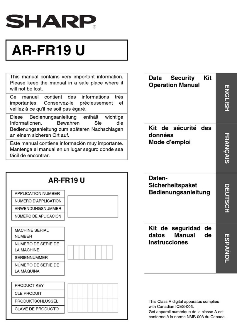
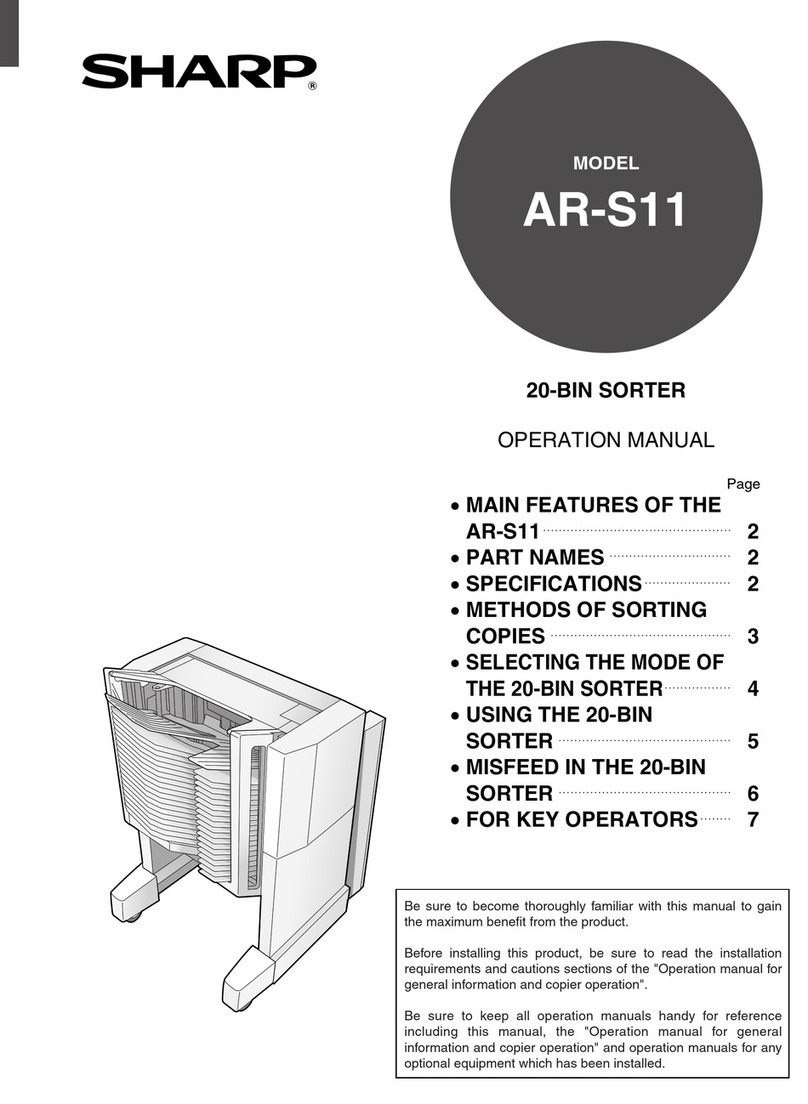
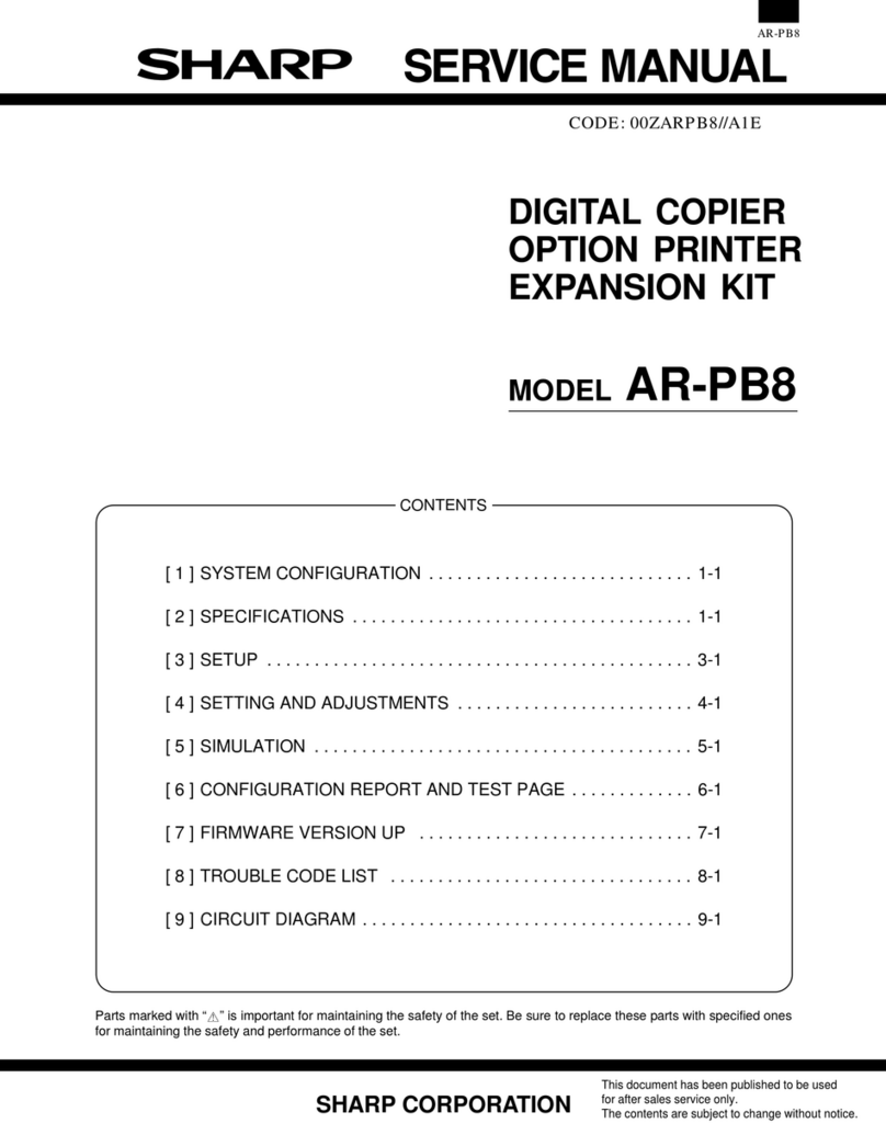
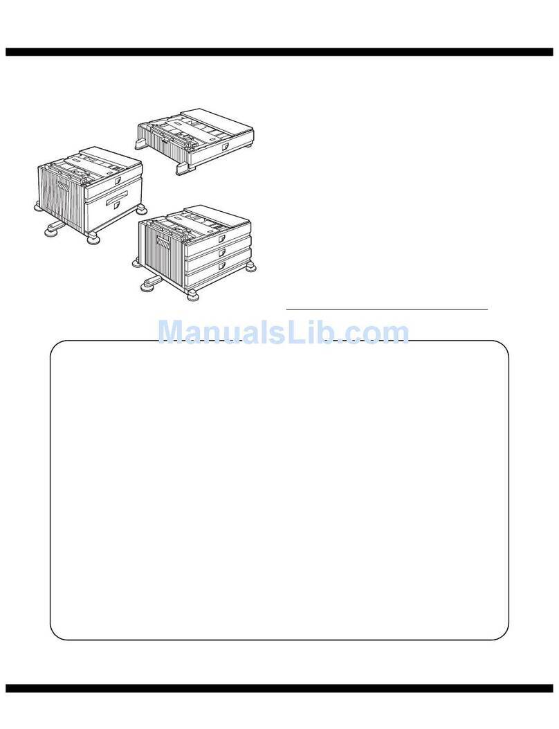
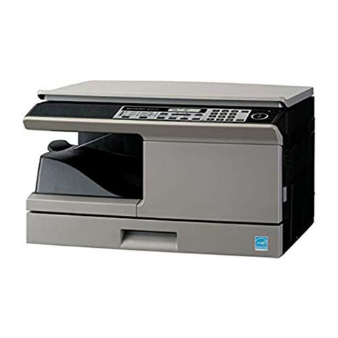
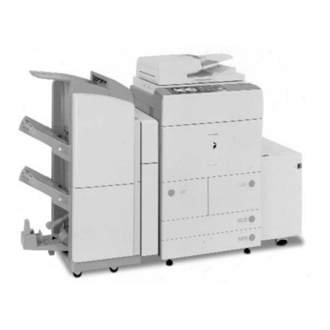
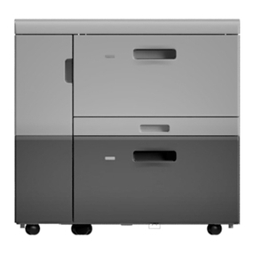
Sharp AR-D24 User manual

CODE : 00Z
qSERVICE MANUAL
CONTENTS
Parts marked with "!" are important for maintaining the safety of the set. Be sure to replace these parts with specified
ones for maintaining the safety and performance of the set.
SHARP CORPORATION This document has been published to be used
for after sales service only.
The contents are subject to change withoutnotice.
ARD25//A1E
Digital copier
: Paper feed unit
AR-D24
MODEL AR-D25
[1] PRODUCT OUTLINE . . . . . . . . . . . . . . . . . . . . . . . . . . . . . . . . . . 1
[2] SPECIFICATIONS . . . . . . . . . . . . . . . . . . . . . . . . . . . . . . . . . . . . 1
[3] UNPACKING AND INSTALLATION . . . . . . . . . . . . . . . . . . . . . . . 2
[4] EXTERNAL VIEW AND INTERNAL STRUCTURE . . . . . . . . . . . 8
[5] OPERATIONAL DESCRIPTION. . . . . . . . . . . . . . . . . . . . . . . . . . 9
[6] DISASSEMBLY AND ASSEMBLY . . . . . . . . . . . . . . . . . . . . . . . . 9
[7] MAINTENANCE . . . . . . . . . . . . . . . . . . . . . . . . . . . . . . . . . . . . . 11
[8] ELECTRICAL SECTION. . . . . . . . . . . . . . . . . . . . . . . . . . . . . . . 12
250-sheet paper
feed unit
500-sheet paper
feed unit


AR-D25/D24 PRODUCT OUTLINE
– 1 –
[1] PRODUCT OUTLINE
The 250-sheet paper feed unit and the 500-sheet paper feed unit are
the optional paper feed cassettes for the digital copier, and they are the
same structure as the 250-sheet cassette of the copier.
The combination of the copier and the paper feed cassette is as shown
below:
[2] SPECIFICATIONS
1. Paper feed unit
Copier
Standard cassette
250-sheet paper feed unit
250-sheet cassette
250-sheet cassette
500-sheet paper
feed unit
(1-Tray Model)
Copier
Standard cassette
250-sheet paper feed unit
250-sheet cassette
250-sheet cassette
500-sheet paper
feed unit
Standard cassette
(2-Tray Model)
AR-D24 AR-D25
Paper
feed step(s) 1-step 2-step
Paper feed
capacity 250 sheets x 1 step 250 sheets x 2 steps
Size detection None
(The paper size is set by the user program.)
Paper feed
detection Available
Paper feed size A3, B4, A4, A4R, B5, B5R
11 x 17, 8.5 x 14, 8.5 x 13, 8.5 x 11, 8.5 x 11R,
8K, 16K, 16KR
Paper weight 56 ~ 90g/m2 (15 ~ 24lbs)
Shipping size AB series: A4
Inch series: 8.5 x 11
Size selection
User operation (Size setting by the user program)
Japan: A3, B4, A4, A4R, B5, B5R
Inch series: 11 x 17, 8.5 x 14, 8.5 x 11, 8.5 x 11R
EX AB series: A3, B4, A4, A4R
Inch series foolscap area:
11 x 17, 8.5 x 14, 8.5 x 13, 8.5 x 11,
8.5 x 11R
EX AB series foolscap area:
A3, B4, A4, A4R, 8.5 x 13
Cassette
detachment Possible by the user
Heater Available only in Japan model
Power source Supplied from the machine.
External
dimension (mm)
W: 590 x D: 471 x H: 88
(Jut portion is not
included.)
W: 590 x D: 471 x H: 173.5
(Jut portion is not
included.)
Weight About 4.7kg
(With cassette) About 10.0kg
(With cassette)
Power
consumption 5.6W 8.4W

AR-D25/D24 UNPACKING AND INSTALLATION
– 2 –
[3] UNPACKING AND INSTALLATION
1. Unpacking
(AR-D24)
(AR-D25)
2. Installation
Included parts
1) Remove the document cover.
Lift the document cover from the copier and tilt it to the rear side to
remove it.
2) Remove the rear cabinet.
Remove the screw and remove the cover. Then, remove the five screws
and remove the rear cabinet.
3) Remove the copier rear cover.
Remove the two screws and remove the rear cover.
Part name Quantity
Screw (Fixing plate) 8
Screw 2
Screw 1
Fixing plate 3
Fixing plate 1
Connection gear 1

AR-D25/D24 UNPACKING AND INSTALLATION
– 3 –
4) Make a hole for connector.
• Copier (1-tray model)
Cut out the portion shown in the illustration with nippers or the like.
• Copier (2-tray model)
Press the portion shown in the illustration with a screwdriver or the
like to remove it.
5) Remove the second cassette rear cover.
Remove the rear cover which is attached to the 250-sheet paper feed
unit.
Remove the rear cover (upper stage) from the 500-sheet paper feed
unit.
6) Install the copier onto the 250-sheet paper feed unit.
Put the copier on the 250-sheet paper feed unit, and fix with the fixing
plates and the screws.
• Copier (1-tray model) + 250-sheet paper feed unit
• Copier (2-tray model) + 250-sheet paper feed unit

AR-D25/D24 UNPACKING AND INSTALLATION
– 4 –
• Copier (1-tray model) + 500-sheet paper feed unit
• Copier (2-tray model) + 500-sheet paper feed unit
7) Remove the connection gear lock.
Remove the connection gear lock (with the red tug) after setting.
8) Connect the connector
Connect the optional relay harness contained in the 1-tray model (2-tray
model) paper feed unit to the PWB of the copier.
• Optional relay harness
• Copier (1-tray model) + 250-sheet paper feed unit

AR-D25/D24 UNPACKING AND INSTALLATION
– 5 –
• Copier (2-tray model) + 250-sheet paper feed unit
• Copier (1-tray model) + 500-sheet paper feed unit
• Copier (2-tray model) + 500-sheet paper feed unit
9) Remove the cassette packing fixtures.
Pull the cassette until it stops.
Turn and remove the packing fixture which is fixing the paper pressure
plate inside the cassette in the direction of arrow.
10) Set the cassette side plate.
Hold the knob of the cassette side plate, slide it and set to the position
of the paper size to be used.

AR-D25/D24 UNPACKING AND INSTALLATION
– 6 –
11) Install the cassette rear edge plate.
Install the cassette rear plate to the position of the paper size to be
used.
12) Set the paper.
When setting the paper, do not exceed the height of the indication label.
Note: To make the paper center shift adjustment and the lead edge
adjustment, insert the power plug of the copier into the
power outlet, turn on the power switch, and perform the fol-
lowing procedure.
13) Perform the center shift adjustment.
Set a document on the document glass and make a copy.
*If the image center is shifted, perform the following procedure.
1. Execute SIM 50-10 with the key operations on the copier.
2. Turn on the Auto lamp and the lamp of a corresponding tray by
Light and Dark key, Enter the set value with the keys on the opera-
tion panel to perform the center shift adjustment, make a copy
again, and check that the center is not shifted.
• When the set value is increased, the image is shifted to the rear
side.
• When the set value is decreased, the image is shifted to the front
side.
After completion of the adjustment, press the key to cancel the
mode.
14) Perform the lead edge adjustment.
Set a document on the document glass, and make a copy.
1. Execute SIM 50-1 with the key operations on the copier.
2. Turn on the Auto lamp and the lamp of a corresponding tray by
Light and Dark key, Enter the set value with the keys on the opera-
tion panel and make a copy to check that the lead edge is within the
specified range.
• When the set value is increased, the copy image moves forward.
• When the set value is decreased, the copy image moves back-
ward.
After completion of the adjustment, press the key to cancel the
mode.
cannot stack
more than this line.
C 5 0 1 0
[Program key]
#
Paper output direction
Front side
Printin
g
side
Rear side
Center line of image
Center line
of paper
Output direction
1
Leading edge
Printing side
Printing side
Output direction Center line
of paper
Leading edge
Center line of image 1
CA
C 5 0 0
[Program key]
# 1
CA

AR-D25/D24 UNPACKING AND INSTALLATION
– 7 –
15) Changing a tray’s paper size setting
Follow these steps to change a tray’s paper size setting.
Note:
• The paper size setting cannot be changed when the machine has
stopped temporarily due to running out of paper or a misfeed, or
during interrupt copying.
• During printing (even in copy mode), the paper size setting cannot
be changed.
• 5-1/2” x 8-1/2” size paper can only be selected in upper paper tray.
• Do not load paper that is a different size than the paper size set-
ting. Copying will not be possible.
1. Hold down the [PAPER SIZE ENTER] key for more than 5 seconds
to set the selected paper size.
The currently selected paper feed location indicator will blink and
the corresponding paper size (which is currently set) indicator will
light steadily. All other indicators will go out.
2. Use the [TRAY SELECT] key ( ) to select the paper tray for
which you wish to change the paper size setting.
Each time the [TRAY SELECT] key ( ) is pressed, a paper tray
will be indicated with a blinking paper feed location indicator.
3. Use the [ORIGINAL SIZE ENTER] key to select the paper size.
The indicator of the selected paper size lights up.
4. Squeeze the lock lever of the front guide and slide the front guide to
match the width of the paper, and move the left guide to the appro-
priate slot as marked on the tray.
• The front guide is a slide-type guide. Grasp the locking knob on
the guide and slide the guide to the indicator line of the paper to
be loaded.
• The left guide is an insert-type guide. Remove it and then insert it
at the indicator line of the paper to be loaded.
• When using 11” x 17” sized paper store the left guide in the slot
at the left front of the paper tray.
5. Press the [START] key ( ) and then the [PAPER SIZE ENTER]
key.
To change0 the paper size setting of another tray, repeat steps 2 to
3 after pressing the [START] key ( ).
Note: Affix the paper size label for the paper size selected in step 3 to
the label position on the right end of the tray.
GINAL
PAPER
SIZE
11
X
17
8½
X
14
8½
X
11
8½
X
11
8½
X
5½
EXTRA
TRAY
SELECT
ORIGINAL SIZE
ENTER
GINAL
PAPER
SIZE
11
X
17
8½
X
14
8½
X
11
8½
X
11
8½
X
5½
EXTRA
Left guide
Front guide
START

AR-D25/D24 EXTERNAL VIEW AND INTERNAL STRUCTURE
– 8 –
[4] EXTERNAL VIEW AND INTERNAL STRUCTURE
1. External view
2. Internal structure
Sensors and detectors
No. Name No. Name No. Name
1 Paper feed tray 2 2-step paper feed right cover 3 1-step paper feed right cover
No. Code Name Type Function, operation Remark
1 DRS1 Door open/close sensor Photo transmission Detects door open/close.
2 PPD1 Paper entry sensor Photo transmission Detects paper transport.
3 CSS1 Paper empty sensor Photo transmission Detects paper presence/empty.
4 CASS1 Cassette detection SW Contact Detects cassette installation.
5 FSOL1 Transport solenoid DC solenoid Transports paper. (for clutch)
6 PSOL1 Paper feed solenoid DC solenoid Feeds paper. (For clutch)
7 PPD2 Paper entry sensor Photo transmission Detects paper transport. AR-D25 only
8 CSS2 Paper empty sensor Photo transmission Detects paper in the cassette. AR-D25 only
9 CASS2 Cassette detection SW Contact Detects cassette installation. AR-D25 only
10 PSOL2 Paper feed solenoid DC solenoid Feeds paper. AR-D25 only
11 PWB Interface PWB — —
123
1
11 32165
4
9
10
7
8

AR-D25/D24 OPERATIONAL DESCRIPTION
– 9 –
[5] OPERATIONAL DESCRIPTION
1. Paper transport path
2. Operational descriptions
The operations are controlled by the main body of the copier. the paper
feed roller (semi-circular roller) and the transport roller are driven by the
gear of the copier.
Paper is separated by the paper feed roller and the separation pawl,
and detected by the PF sensor, then transported to the Resist roller by
the transport roller.
[6] DISASSEMBLY AND ASSEMBLY
1. Rear cover
[AR-D24]
[AR-D25]
2. Paper feed unit section
[AR-D24]
No. Name Operation
1 Paper feed roller Picks up paper.
2 Separation pawl Prevents against double feed of paper.
3 Transport roller Transports paper.
4 Paper entry sensor Detects paper transport.
5 Resistroller Makes synchronization between the
paper lead edge and the image lead
edge.
Copier
cassette
250-sheet paper
feed unit (upper)
Paper feed roller
PF sensor
Transport roller
250-sheet paper
feed unit (Lower)
Copier
To copier's PS
250-sheet paper feed unit
Paper lead edge
12
5
3
4
1
1
2
1
1
2
1
23
5
3
4

AR-D25/D24 DISASSEMBLY AND ASSEMBLY
– 10 –
[AR-D25]
3. Paper feed solenoid, transport solenoid
4. Transport roller gear section
5. Transport roller
[AR-D24]
2
3
1
3
1
5
6
6
4
1
2
1
2
(1)
(1)
(2)
(3)
AB

AR-D25/D24 MAINTENANCE
– 11 –
[Only the upper row of AR-D25]
6. Paper feed roller clutch
Note: When asembling the paper feed roller cluch, fit and insert section
A (D cut) into the shaft as shown in the figure.
7. Paper feed roller
*Be sure to rotate this part 180 degrees(It turns upward) after attach-
ment.
[7] MAINTENANCE
*1 : Replace = 150K
Note: For disassembly and assembly of the paper feed roller and the
transport roller, refer to [6] DISASSEMBLY AND ASSEMBLY.
(1)
(1)
(2)
(3)
AB
3
A
1
2
No. Name Work item When
service call Remark
1 Paper feed roller PA ass’y *1 Cleaning o
2 Transport roller Cleaning o
1
2
1
2

AR-D25/D24 ELECTRICAL SECTION
– 12 –
8 7 6 5 4 32 1
A
B
C
D
12345678
D
C
B
A
PPD1
CASS2
FSOL1
CSS1
PPD2
PSOL1
CSS2
DRS1
PSOL2
CASS1
IC1
5V1
IC3
5V1
IC2
24V 24V
24V
24V
SELA
SELB
SELB
Y1
Y2
5V2
5V2
5V2
5V2
5V2
PSOL1
FSOL1
PSOL2
Y3
FSOL2
PSOL3
FSOL3
INTERFACE PWB
5V1 5V2 24V
3
1. BLOCK DIAGRAM
1/1
Copier body
Data selector
Driver array
Data selector
Lower connection CS
2nd/Multi step CS only
Multi step CS only
[8] ELECTRICAL SECTION

AR-D25/D24 ELECTRICAL SECTION
– 13 –
8 7 6 5 4 32 1
A
B
C
D
12345678
D
C
B
A
1
2
1
2
3
5V2
PPD1
LGND
LGND
CASS1
CASS1
PPD1
2
1
3
5V2
DRS1
LGND
DRS1
PSOL1
FSOL1
1
21
2
24V1
/PSOL1
1
21
2
24V1
/FSOL1
2
1
35V2
CSS1
LGND
CSS1
CS INTERFACE PWB
2ND CS
1. 2nd CS TYPE AR-D24
175778-2
DF3-3S-2C
DF3-3S-2C
DF3-3S-2C
SMP-02V-NCSMR-02V-N
SMP-02V-BCSMR-02V-B
BR
GY
BR
OR
PL
LB
RD
BL
RD
BL
OR
OR
OR
GY
GY
GY
RD
BL
RD
BL
AC100L
HEATER DH1
AC100L
PPD1
BK
PSOL1
ELP-02V
1
FSOL1
BK
2
2
WH
PWB
UNIT REAR VIEW
ELP-02V
ELR-02V
2
AC100N
CSS1
WH
2nd CS UNIT
CASS1
DRS1
ELR-02V
AC100N
1
JAPAN ONLY
FOR LOWER OPTION CS
TO 2ND OR MAIN BODY
(UPPER UN)
2AC100L
1AC100N
1
CASS1
8
7
4
24V1
/PSOL1
10
12
13
11
CSS1
LGND
PPD1
DRS1
2
/FSOL1
24V1
24V
24V
PSOL1
FSOL1
FSOL2
PSOL2
PSOL3
PGND
PGND
LGND
LGND
SELB
SELC
SELA
Y3
Y2
Y1
5V1
RD
RD
PK
PK
GY
GY
GY
BR
PL
PL
PL
OR
OR
123 4 56789
1011 12 13 1415 1617 1819 20
(B22B-PHDSS)
CN-A
CN-B
(B16B-PHDSS)
5V2
PK
PK
PK
BR
GY
FSOL3 PK
BR
5
1
15
N.C.
16
14
21 22
5V2
N.C.
N.C.
9
6
3
PGND
15
2
10 16
8
14
PSOL2
Y1
LGND
FSOL1
13
5V2
SELA
12
PGND
19
5
LGND
17
3
SELB
11
1
PSOL3
9
FSOL3
7
Y3
FSOL2
24V
Y2
24V
PSOL1
5V1
20
SELC
18
46
PHDR-20VS
TO 2ND OR MAIN BODY
(UPPER UN)
18
4
15
2
FSOL3
10 16
FSOL2
8
14
PSOL2
Y2
LGND
LGND
PGND
13
PGND
5V2
N.C.
12
CN-C
PSOL3
19
5
SELB
Y3
17
3
(B20B-PHDSS)
SELA
11
1
SELC
9
N.C.
7
N.C.
24V
24V
5V1
20
6
N.C.
N.C.
N.C.
N.C.
N.C.
GY
2. ACTUAL WIRING DIAGRM

AR-D25/D24 ELECTRICAL SECTION
– 14 –
8 7 6 5 4 32 1
A
B
C
D
12345678
D
C
B
A
1
2
1
2
35V2
PPD1
LGND
LGND
CASS1
CASS1
PPD1
2
1
35V2
DRS1
LGND
DRS1
PSOL1
FSOL1
1
21
2
24V1
/PSOL1
1
21
2
24V1
/FSOL1
2
1
35V2
CSS1
LGND
CSS1
CASS1
8
7
4
24V1
/PSOL1
10
12
13
11
CSS1
LGND
PPD1
DRS1
2
/FSOL1
24V1
24V
24V
PSOL1
FSOL1
FSOL2
PSOL2
PSOL3
PGND
PGND
LGND
LGND
SELB
SELC
SELA
Y3
Y2
Y1
5V1
RD
RD
PK
PK
GY
GY
GY
BR
PL
PL
PL
OR
OR
123 4 56789
1011 12 13 1415 1617 1819 20
CS INTERFACE PWB
MULTI CS
(B22B-PHDSS)
CN-A
CN-B
(B16B-PHDSS)
175778-2
DF3-3S-2C
DF3-3S-2C
DF3-3S-2C
SMP-02V-NCSMR-02V-N
SMP-02V-BCSMR-02V-B
5V2
BR
GY
BR
OR
PL
LB
RD
BL
RD
BL
OR
OR
OR
GY
GY
GY
RD
BL
RD
BL
PK
PK
PK
BR
GY
FSOL3 PK
BR
5
1
2
2
1
2
1
PSOL2
RD
PPD2
CASS2
CASS2
LGND
LGND
PPD2
5V2 3
2
5V2
1
2
1
DF3-3S-2C
GY
BR
CSS2
1
BL
15
BR
LGND
24V1
LB
CSS2
CSS2
N.C.
16
OR
BL
/PSOL2
DF3-3S-2C
CASS2
SMR-02V-N SMP-02V-NC
14
RD
GY
OR
175778-2
PPD2
3
21 22
5V2
N.C.
N.C.
9
6
3
ELP-02V
UPPER CS
AC100L
ELR-02V
ELP-02V
AC100L
DRS1
PPD2
UNIT REAR VIEW
HEATER DH3
ELP-02V
PSOL1
2
CASS2
CASS1
LOWER CS
AC100N
1
HEATER DH2
MULTI CS UNIT
PPD1
PSOL2
ELR-02V
BK 2
CSS1
FSOL1
PWB
CSS2
PGND
15
2
10 16
8
14
PSOL2
Y1
LGND
FSOL1
13
5V2
SELA
12
PGND
19
5
LGND
17
3
SELB
11
1
PSOL3
9
FSOL3
7
Y3
FSOL2
24V
Y2
24V
PSOL1
5V1
20
SELC
18
46
PHDR-20VS
JAPAN ONLY
TO 2ND OR MAIN BODY
(UPPER UN)
TO 2ND OR MAIN BODY
(UPPER UN)
1 AC100N
AC100L 2
1
2
1 AC100N
WH
1
2
LOWER UNIT
1
2
3
4
5
6
7
8
1
2
3
4
5
6
7
8
BR
GY
GY
BR
OR
GY
LB
OR
RD
BL
CASS2
LGND
LGND
PPD2
5V2
LGND
CSS2
5V2
24V1
/PSOL2
GY
UPPER UNIT
LOWER UNIT
UPPER UNIT
SMR-08V-N SMP-08V-NC
2. MULTI CS TYPE AR-D25

AR-D25/D24 ELECTRICAL SECTION
– 15 –
3. INTERFACE PWB CIRCUIT DIAGRAM
8 7 6 5 4 32 1
A
B
C
D
12345678
D
C
B
A

AR-D25/D24 ELECTRICAL SECTION
– 16 –
AR-D25 PARTS ARRANGEMENT
[PARTS SURFACE]
[SOLDER SURFACE]
4. PARTS ARRANGEMENT
AR-D24 PARTS ARRANGEMENT
[PARTS SURFACE]
24V1
6
4
2
B16B-PHDSS
CN-B
PPD1
CASS2
CASS1
LGND
/FSOL1
15
13
/PSOL2
N.C.
CSS2
11
9
16
10
7
5
3
1
24V1
CSS1
PPD2
12
24V1
/PSOL1
5V2
14
8
DRS1
43
5V2
Y1
18
5V1
15
24V
11
FSOL1
16
8
14
20
PSOL3
2
LGND
PSOL1
10
5
17
FSOL2
21
CN-A
7
12
13
1
9
PGND
22
B22B-PHDSS
6
FSOL3
19
SELC
PSOL2
SELA
24V
PGND
SELB
LGND
Y3
Y2
N.C.(5V1)
N.C.(5V2)
N.C.
PSOL3
19
24V
1
20
7
16
PSOL2
5V1
LGND
11
15
34
9
N.C.
B20B-PHDSS
13
17
5
CN-C
2
18
Y2 14
PGND
SELB
6
10
8
12
SELC
24V
Y3
SELA
FSOL2
LGND
5V2
N.C.
PGND
FSOL3
[SOLDER SURFACE]
24V1
6
4
2
B16B-PHDSS
CN-B
PPD1
CASS2
CASS1
LGND
/FSOL1
15
13
/PSOL2
N.C.
CSS2
11
9
16
10
7
5
3
1
24V1
CSS1
PPD2
12
24V1
/PSOL1
5V2
14
8
DRS1
43
5V2
Y1
18
5V1
15
24V
11
FSOL1
16
8
14
20
PSOL3
2
LGND
PSOL1
10
5
17
FSOL2
21
CN-A
7
12
13
1
9
PGND
22
B22B-PHDSS
6
FSOL3
19
SELC
PSOL2
SELA
24V
PGND
SELB
LGND
Y3
Y2
N.C.(5V1)
N.C.(5V2)
N.C.
PSOL3
19
24V
1
20
7
16
PSOL2
5V1
LGND
11
15
34
9
N.C.
B20B-PHDSS
13
17
5
CN-C
2
18
Y2 14
PGND
SELB
6
10
8
12
SELC
24V
Y3
SELA
FSOL2
LGND
5V2
N.C.
PGND
FSOL3

SHARP CORPORATION This document has been published to be used for
after sales service only.
The contents are subject to change without notice.
qPARTS GUIDE
本書はサービス活動用に作成した資料です。
一部内容が製品の改良・改善等により予告
なしに変わることがあります。
デジタル複合機オプション
デジタル複合機オプションデジタル複合機オプション
デジタル複合機オプション
1
11
1 段給紙デスク
段給紙デスク段給紙デスク
段給紙デスク
2
22
2段給紙デスク
段給紙デスク段給紙デスク
段給紙デスク
Digital Copier
Digital CopierDigital Copier
Digital Copier Option
OptionOption
Option
Stand/1
Stand/1Stand/1
Stand/1×
××
×250 Sheet Paper Drawer
250 Sheet Paper Drawer250 Sheet Paper Drawer
250 Sheet Paper Drawer
Stand/2
Stand/2Stand/2
Stand/2 ×
××
×250 Sheet Paper Drawer
250 Sheet Paper Drawer250 Sheet Paper Drawer
250 Sheet Paper Drawer
AR-D24
MODEL AR-D25
このパーツガイドに掲載されている表示価格ランクは消費税抜きです。
CONTENTS
11ST トレイ外装 (1ST Tray exteriors)[AR-D24]
21ST トレイ給紙ユニット (1ST Tray paper feeding unit)[AR-D24]
32ND トレイ外装 (2ND Tray exteriors)[AR-D25]
42ND トレイ給紙ユニット (2ND Tray paper feeding unit)[AR-D25]
5250 枚トレイユニット (250 sheets tray unit)
6梱包材 &付属品 (Packing material & Accessories)
■ 索引 (Index)
AR-D25
AR-D24

– 1 –
補修部品のランク付
市場における補修部品の在庫管理が、適正に運営出来る手助けとなることを、目的とします。
Aランク :メンテナンスパーツ、メンテナンスパーツには入っていないがメンテナンスパーツに近い消耗パーツ。
Bランク :性能・機能パーツ(センサー、クラッチ等の電気パーツ)、消耗パーツ。
Eランク :基板含むユニットパーツ。
Dランク :整備パーツ(外装、パッキング、同梱パーツ)。
Cランク :上記ランク以外のパーツ(基板の子部品を除いたもの)。
DEFINITION
Rank A : Maintenance parts, and consumable parts which are not included in but closely related to maintenance parts
Rank B : Performance/function parts (sensors, clutches, and other electrical parts), consumable parts
Rank E : Unit parts including PWB
Rank D : Preparation parts (External fitting, packing, parts packed together)
Rank C : Parts other than the above (excluding sub components of PWB)
安全性・信頼性確保のため部品は、必ず正規のものをご使用下さい。
!印の商品は、安全上重要な部品です。交換をする時は、安全及び性能維持のため必ず指定の部品をご使用下さい。
Because parts marked with "!" is indispensable for the machine safety maintenance and operation, it must be replaced with
the parts specific to the product specification.
F当モデルのサービス資料には、この資料以外にサービスマニュアル (回路図含む )があります。合わせてご利用下さい。
FOther than this Parts Guide, please refer to documents Service Manual(including Circuit Diagram)of this model.
FPlease use the 13 digit code described in the right hand corner of front cover of the document, when you place an order.
FFor U.S. only-Use order codes provided in advertising literature. Do not order from parts department.
11ST トレイ外装 (1ST Tray exteriors)[AR-D24]
NO. PARTS CODE PRICE RANK NEW
MARK PART
RANK DESCRIPTION
Ex. Ja.
1GCOV-0020QSE1 AQ EQ N D Rear cover 後カバー
2GGAD-0001QSZZ AE DJ C Edge gard upper エッジガード 上
3GGAD-0002QSZZ AE DS C Edge gard lower エッジガード 下
4LSUPP0083FCZZ AB DJ C Supporter(LCBS-3) 基板サポーター
5LPLTM0116QSZZ AQ EQ C Joint plate R 連結板 R
7XEBSE40P12000 AA DD C Screw(4×12) ビス
8GCOV-0019QSZ2 AT EZ N D Front cover 前カバー
9PGIDM0049QSE2 BA FX N C Guide L ガイド L
10 PGIDM0048QSE2 BB FX N C Guide R ガイド R
11 MSPRC0141QSZZ AB DJ C Transport PG lock spring 搬送 PG ロックスプリング
12 MLOKZ0001QSZZ AC DJ C Transport PG lock 搬送 PG ロック
13 NGERH1169FCZZ AF DS C Joint gear 連結ギア
14 PRNGP0019FCZZ AA DD C V ring(GTW-6) V リング
15 DHAI-0326QSZZ AM EG C CAS harness CAS ハーネス
16 CPWBF0019QSE5 AV FG E 1ST tray interface PWB 1 段トレイ中継基板
18 MSPRD0135QSZZ AD DJ C Joint earth spring 連結アーススプリング
19 GLEGG0064FCZZ AC DJ C Rubber foot ゴム足
21 MARMP0015QSZZ AD DJ C 1ST door arm 一段ドアアーム
22 NROLP1060FCZZ AF DS C U-turn roller U ターンローラー
23 MSPRT0129QSZ1 AC DJ C Roller spring 従動ローラースプリング
24 GCOV-0021QSE2 AP EQ N D 1ST right cover 一段右カバー
25 LPLTM0113QSZZ AH DX C Guide R joint plate ガイド R連結板
27 XEPSD30P08X00 AA DD C Screw(3×8X) ビス
28 XHBSE30P14000 AA DD C Screw(3×14) ビス
30 LPLTM0135QSZZ AF DS C 2ND joint earth plate 2ND 連結アース板
31 LPLTM0138QSZZ AD DJ C 2ND joint earth plate left back 2ND 連結アース板左後
33 PSHEZ0172QSZZ AB DJ C Front sheet 2 (Europe) フロントシート 2
34 PSHEZ0173QSZZ AB DJ C Right cover sheet (Europe) 右カバーシート
35 PSPO-0008QSZZ AC DJ C Rear cover cushion 1 (Europe) 後カバースポンジ 1
36 PSPO-0009QSZZ AD DJ C Rear cover cushion 2 (Europe) 後カバースポンジ 2
37 PSPO-0010QSZZ AD DJ C Guide R cushion F (Europe) ガイド Rスポンジ F
38 PSPO-0011QSZZ AD DJ C Guide R cushion R (Europe) ガイド Rスポンジ R
39 PSPO-0014QSZZ AG DS C Right cover cushion 3 (Europe) 右カバースポンジ 3
40 PSHEZ0171QSZZ AD DJ C Front sheet 1 (Europe) フロントシート 1
41 LHLDW3142KCZZ AC DD C Cable band ケーブルバンド
This manual suits for next models
1
Table of contents
Languages:
Other Sharp Printer Accessories manuals

Sharp
Sharp AR-NB2 User manual

Sharp
Sharp AR-S11 User manual

Sharp
Sharp AR-NB2 Setup guide
Sharp
Sharp AR-D28 User manual

Sharp
Sharp AR-FR22 U User manual

Sharp
Sharp ARFX13 - Fax Interface Card User manual

Sharp
Sharp MX-B201D User manual

Sharp
Sharp AR-P15 User manual

Sharp
Sharp AR-PB9ML User manual

Sharp
Sharp AR-FR19 U User manual
Popular Printer Accessories manuals by other brands

Digital Equipment
Digital Equipment DEClaser 3500 installation guide

Ricoh
Ricoh PB1170 Field service manual

Canon
Canon BW Expansion Bus-C1 Service manual

Output Technology
Output Technology LaserMatrix Table Top Stacker Replacement parts catalog

Tektronix
Tektronix Phaser 540 user guide

Rico
Rico LCIT RT5110 Field service manual