SORG Mio Service manual

Service Record Mio (Design 2018) 1 of 32
2019-07-16
Mio
Design 2018
Unique people, unique solutions.
Service Record Mio (Design 2018)
ENG
Service Record
In the following all individual adjustments of the wheelchair are
described. These adjustments require tools and specialised
knowledge. Please leave the adjustments to a qualied rehab
consultant.

2 of 32 Service Record Mio (Design 2018)
Service Record Mio (Design 2018) 2019-07-16
Imprint
SORG Rollstuhltechnik GmbH+Co.KG
Benzstraße 3-5
68794 Oberhausen-Rheinhausen / Germany
Tel. +49 7254-9279-0
Fax +49 7254-9279-10
E-Mail [email protected]
Web www.sorgrollstuhltechnik.de
Revision status
2019-07-16
Technical status
Technical changes and misprints reserved. The
pictures in this Instructions for use can dier
from the actual equipment components. How-
ever, a corresponding conduction is possible.
Copyright
All texts, pictures and graphics underlie co-
pyright protection. All rights, including co-
pying, publishing, editing and translating,
remain reserved. © by SORG Rollstuhltech-
nik GmbH+Co. KG Benzstraße 3-5, 68794
Oberhausen-Rheinhausen / Germany.
Our terms and conditions can be found
on our order forms and at www.sorgrollstuhl-
technik.de/impressum.

Service Record Mio (Design 2018) 3 of 32
2019-07-16
Table of content
1 Wheelchair overview 4
2 General information 5
2.1 General indications 5
2.2 Documentation indications 5
2.3 Required torques and tools 5
2.4 Explanation of sysmbols 6
2.5 General safety instructions 7
3 Assembly groups 8
3.1 Assembly group wheels 8
3.1.1 Centre of gravity/ wheelbase 8
3.1.2 Camber 8
3.1.3 Casters 8
3.2 Assembly group seat 9
3.2.1 Seat height and seat tilt 9
3.2.2 Widening the seat 10
3.2.3 Seat depth 11
3.2.4 Adjusting seat plate 12
3.2.5 Adjusting the seat support brackets12
3.2.6 Adjusting the back 12
3.2.7 Centre of gravity 13
3.3 Assembly group back 14
3.3.1 Standard back 14
3.3.2 Adjusting the back angle 15
3.3.3 Back with back tubes 16
3.4 Assembly group leg support 18
3.4.1 Standard leg support 18
3.4.2 Removable leg support 19
3.5 Assembly group side guards 20
3.5.1 Clothes guard 20
3.6 Assembly group brakes 21
3.6.1 wheel lock 21
3.6.2 Bowden cable 22
3.6.3 Adjusting user handel 22
3.7 Assembly group anti-tipper 23
3.7.1 Adjusting the height 23
3.8 Assembly group truss pads 24
3.8.1 Composition 24
3.8.2 Vertical setting 24
3.8.3 Horizontal setting 25
3.8.4 Fine adjustment of the
truss pad holder 25
3.8.5 Adjusting to the user 25
3.9 Assembly group Outdoor-Front-End 26
3.9.1 Horizontal setting 26
4 Repairs and maintenance 27
4.1 Repairs 27
4.2 Spare parts 27
4.3 Cleaning 27
4.4 Disinfection 27
4.5 Storage 27
4.6 Reinstatement 28
4.7 Disposal 28
4.8 Maintenance/ Inspection 28
5 Technical Data 30
5.1 Data and measurements 30
5.2 Meaning of labels 31
5.3 Declaration of conformity 31

4 of 32 Service Record Mio (Design 2018)
Service Record Mio (Design 2018) 2019-07-16
1 Wheelchair overview
1push handle
2back cushion
3brake lever
4side guard
5seat cushion
6frame
7impact protection
8caster fork
9caster
10 foot plate
11 hand rim
12 curved back plate
13 stabiliser bar
14 rear wheel
15 hand rim
16 anti-tipper
1
3
4
5
6
8
9
1011
2
12
14
16
13
15
7

Service Record Mio (Design 2018) 5 of 32
2019-07-16
2 General information
2.1 General indications
In the following all individual settings, adjustments and repairs as well as the yearly inspection of
the wheelchair are described. These adjustments require tools and specialised knowledge. Please
leave the adjustments to a qualied rehab consultant.
Should questions or suggestions come up then please contact your medical supply store or our
team (+49 7254 9279-0).
2.2 Documentation indications
Please note:
• Information about before sale can be found in the instructions for use
• Infomation for the user can be found in the instructions for use
• For maintenance instructions see: Chapter 4 (Repair & Maintenance)
2.3 Required torques and tools
For the following screws needed torque:
• M5: 5 Nm;
• M6: 7 Nm;
• M6 (axle plate) 10 Nm
• M8: 20 Nm;
• M10 (nut): 25 Nm; (caster)
• quick release axle tting 40 Nm
Needed tools:
• torque wrench (5-50 Nm)
• open end wrench
• ex ratchet handle with socket wrench inserts
• hexagon screw driver
• Phillips screw driver
• at head screw driver
• plastic mallet
• side cutter
• threadlocker (uid)
• bicycle inner tube repair kit
• work bench/jaw vise with rubber pads

6 of 32 Service Record Mio (Design 2018)
Service Record Mio (Design 2018) 2019-07-16
2 General information
2.4 Explanation of symbols
ATTENTION! Warnings for perso-
nal Safety aspects that are of the
utmost importance.
CORRECT safety adjustment/ use
WRONG adjustment/ use
NOT ALLOWED
References to additional/conti-
nuing reading.
Setting or adjusting the angle
open/ close
Turn clockwise
Turn counter-clockwise
steps to be done at the same time
steps to be done after each other
steps to be done on both sides
Use
(A); (B)
1. 1.
1. 2.
;
2x
push/ pull/ insert / move/
Push in specic direction
important detail
correct or proper use/setting
incorrect or improper use/setting
reference from text to detail
point of view
view from top
view from the side
view from the bottom
view from the front
view from the back
fasten parts
remove parts

Service Record Mio (Design 2018) 7 of 32
2019-07-16
2 General information
2.5 General safety instructions
Before each use be sure to check:
• frame, back tubes, attachments and accessories for visible damage, bends, cracks or mis-
sing/loose scews,
• wheels/quick release axles for rm t,
• sucient tire pressure, tire tread,
• functionality of the brakes,
• rm t of the angle adjustment elements/ eccentric clamps,
• rm t of the seat plate/ the back/ the foot plate,
• functionality of the anti-tipper/ seat and back straps,
• if all previously disassembled parts are re-inserted or rmly locked.
There is a risk of injuries (e. g. such as bruising) on all rotating or folding parts, including
adjustments, repairs and transport.
All wheelchair parts are to be handled with care. Do not throw or drop removable parts.
Before repairs or adjustments are made, clean/didinfect the wheelchair and secure it from
tipping over and/or falling down.
Only use original spare parts.
Safety nuts may only be used once. Lossened safety nuts must be replaced by new ones.
Only the regular maintenance of all safety-relevant parts on the wheelchair by a qualied
rehab workshop protects against damage and maintains our manufacturer's warranty.
Combination with products from other manufacturers
The wheelchair may only be combined with the electrical auxiliary drives apporved by the
manufacturer. Restrictions or adaptations as well as the attachment itself must be done by the
supplier of the additional system or the authorized specialist dealer.
Please check the conditions with the manufacturerer of the audiliary drives.
In combination of wheelchair and electric auxiliary drive, certain strains can occur which
can lead to damage to the wheelchair. Slowly approach obstacles and carefully overcome
them so that little force is applied to the caster, driving wheel and wheelchair as a whole.

8 of 32 Service Record Mio (Design 2018)
Service Record Mio (Design 2018) 2019-07-16
3.1.1 Centre of gravity/ wheelbase
3.1 Assembly group wheels
(1) The centre of gravity is set with the seat
support bracket (A) by displacing the seat pla-
te (B) forward/backward and by displacing the
back intake (C).
The centre of gravity is the crucial factor for
an optimal gripping point. The acceptance of
the aid and, therefore, the success of the rehab
programm depend on this (especially for the
younger users). Please use the utmost care
when tting the wheelchair to this point.
The rear wheel is always factory-installed in
the front hole of the rear wheel mount. Only
with an angle adjustable back the rear wheel is
mounted in the rear hole.
(B)
(A)
(1)
(B)
(C)
(A)
(2)
3.1.2 Camber
The camber and toe adjustment settings can be found in the separate service booklet "Camber
and toe compensation". This can be found at http://www.sorgrollstuhltechnik.de
3.1.3 Casters
(2)
To displace/replace the casters:
• remove the screws (A) completely,
• remove the husks,
• change the casters,
• if necessary, guide the husks and wheels
in the new holes (B),
• replace the safety nuts with new ones
and retighten all the screws.
When changing the casters, make sure
that the Casters is mounted in the previous
hole (4 "lower hole, 5" upper hole).

Service Record Mio (Design 2018) 9 of 32
2019-07-16
3.2.1 Seat heigh and seat tilt
3.2 Assembly group seat
The seat height is (next to the centre of grav-
ity) a signicant factor for the ideal length for
turning the driving wheel and causes a positive
division of the child’s strength when using the
wheelchair.
A general rule is: with a straight (and relaxed
shoulder area) stance of the child, the elbows
should reach the side guard. Be sure that when
setting the seat height to check that the child
does not need to lift its shoulders when moving
the wheelchair.
A slight or strong seat tilt allows a safe and
comfortable seat position with a good distri-
bution of the seat pressure and promotes the
straightening of the pelvis.
(1) By alternating the seat angle the seat height
can be changed in 1,5 cm steps up to 4,5 cm
and gives the following seat heights in the front:
Distance top edge of the seat to
ground (without seat cushion!)
degree of
tilting
with
18“
with
20“
with
22“
with
24“ bore degree
A1 315 mm/
31,5 cm
340 mm/
34,0 cm
360 mm/
36,0 cm
385 mm/
38,5 cm B1 without
A2 330 mm/
33,0 cm
355 mm/
35,5 cm
375 mm/
37,5 cm
400 mm/
40,0 cm
B2 without
C1 slight
B1 strong
A3 345 mm/
34,5 cm
370 mm/
37,0 cm
390 mm/
39,0 cm
415 mm/
41,5 cm
B3 without
C2 slight
B2 strong
A4 360 mm/
36,0 cm
385 mm/
38,5 cm
405 mm/
40,5 cm
430 mm/
43,0 cm
B4 without
C3 slight
B3 strong
A5 - 400 mm/
40,0 cm
420 mm/
42,0 cm
455 mm/
45,5 cm
B5 without
C4 slight
B4 strong
• Remove the screws of the seat support-
ing angle
• mount the seat plate in the desired po-
sition,
• replace the screws and tighten them.
When setting the seat height regard the dai-
ly situations (pushing the wheelchair under
a table at school or nursery school etc.). Ac-
cording to the set position of the foot notch,
it must be ensured that the casters can turn
freely 360°.
B5
C4
C3
C2
C1
B4
B3
B2
A5
A4
A3
A2
A5
A4
A3
A2
A1
A1
B1
(1)

10 of 32 Service Record Mio (Design 2018)
Service Record Mio (Design 2018) 2019-07-16
3.2.2 Widening the seat
3.2 Assembly group seat
(1) To increase the seat width by 20 mm / 2
cm, you must remove the rear wheels, prevent
the wheelchair from rolling away and proceed
as follows:
• Completely remove screw connection
between seat plate and seat support
brackets,
• Completely remove screw connection
for depression
• Completely remove side guards,
• Move spacer bushes.
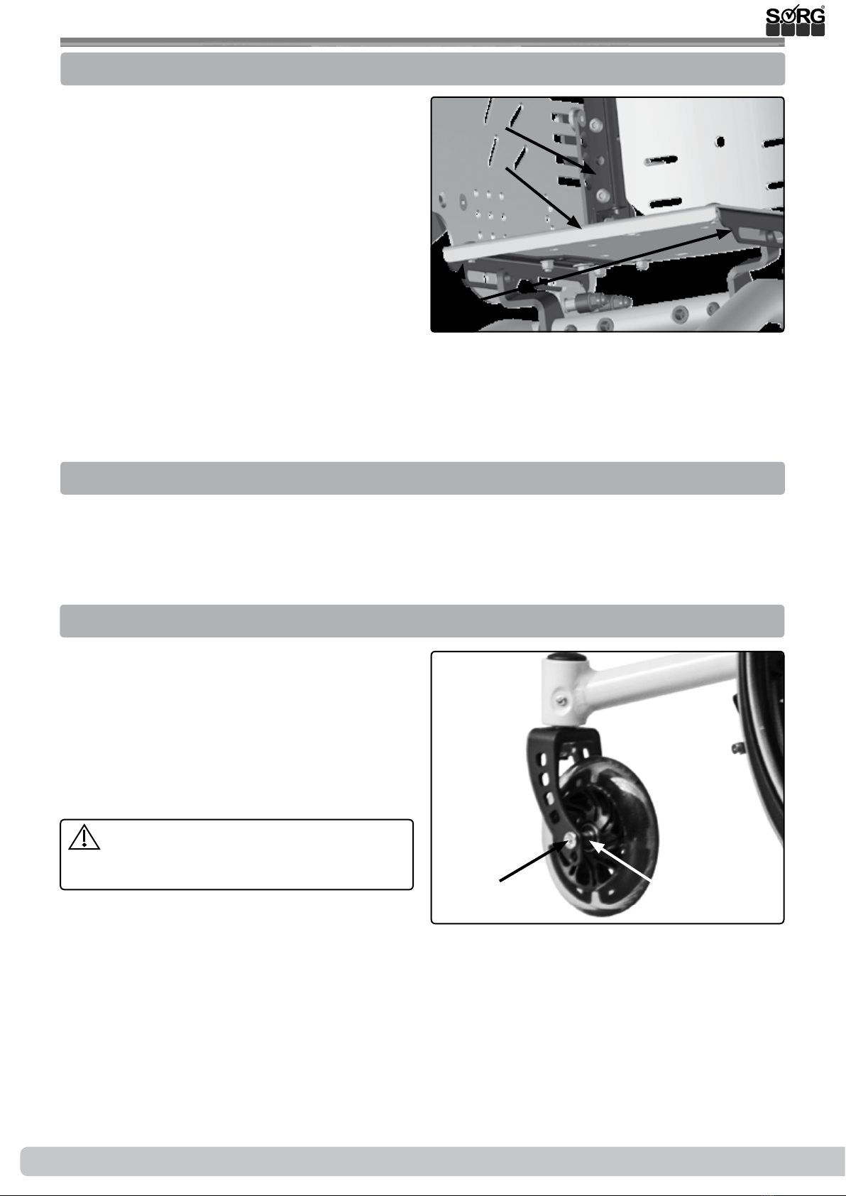
(1) Remove seat plate
• Remove both screws (D) on both sides.
• Leave the seat support bracket (A) con-
nected to the side panels.
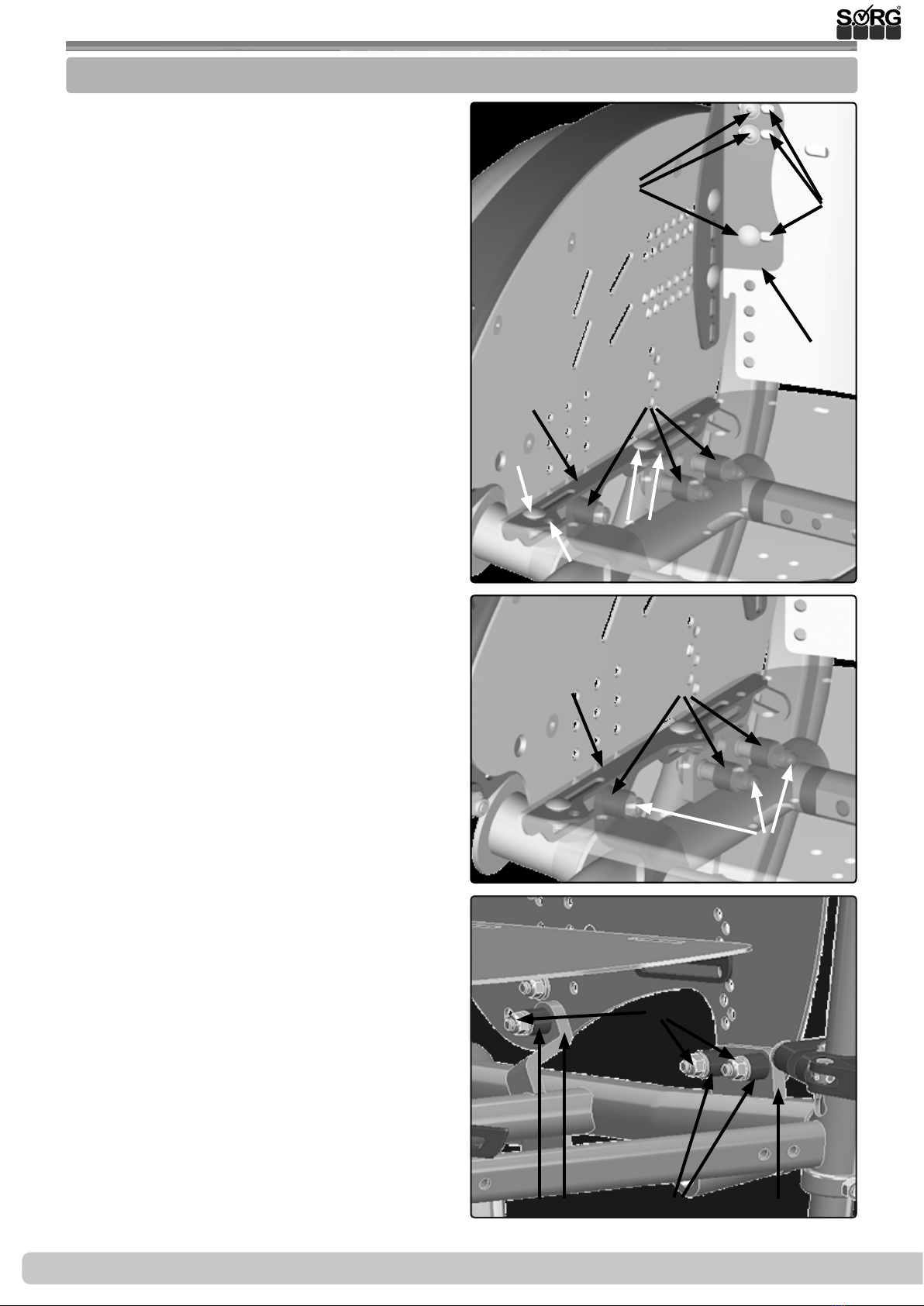
(1) Remove the depression
• Remove all screws (E) on both sides.
• Leave the rear support brackets (C)
connected to the side panels and remo-
ve only the back of the rm curved back
plate
(2) Remove side guards
• Remove all screws (A) on both sides.
• Leave the seat support brackets (B)
connected to the side panels.
• Remove the spacers (C).
(3) Moving the spacers / widening of the
wheelchair
• The wheelchair is delivered by us in
such a way that the spacers (A) neces-
sary for the seat broadening sit on the
inside.
• Move the spacers (A) between the side
panel (B) and the brackets (C).
• Replace all screws (D) and turn them
tight.
After the seat widening sit the spacers (A) on
the outside between side panel and side panel
holder.
(1) Insertion of the depression
• Use the screws (E) to screw the depres-
sion back into the new holes (F).
• Check all screw connections.
• To change the seat height / seat angle:
• Completely remove the screws of the
seat support bracket on both sides,
• Bring the seat plate into the desired
position,
• Reinstall screw connections and tighten
tightly.
(A)
(D)
(F)
(F)
(D)(F)
(C)
(E)
(B)
Seat plate shown trans-
parently
(3)
(C)(C)(A) (A)
(D)
(B)
(A)
(C)(B)
(2)
(1)

Service Record Mio (Design 2018) 11 of 32
2019-07-16
After each change of the seat position, the position of the foot plate must be corrected.
It must be ensured that the steering wheels can rotate freely under the foot plate by 360 °.
When adjusting the seat height, please take into account the domestic situation (accessibility
of tables in kindergarten, at school, etc.).
3.2.3 Seat depth
On the pictures you can see the delivery status
of the Mio (Design 2018):
• (1) seat plate is mounted at the very
back of the seat support bracket (2B),
so it stands behind about 20-30 mm /
2-3 cm above the dump back),
• (2) seat support bracket mounted at the
front,
• (3) Backrest mounted at the back.
(Not with equipment "back angle adjustable")
The seat depth can be innitely changed by
approx. ± 40 mm / 4 cm, by moving the back
of the sink an additional approx. ± 30 mm / 3
cm.
There are three ways you can change the seat
depth:
• by displacing the seat plate,
• by displacing the seat support angle,
• by displacing the rm curved back plate.
(1)
(A)
(3)
(A)
(2) (A)
(B)
3.2 Assembly group seat

12 of 32 Service Record Mio (Design 2018)
Service Record Mio (Design 2018) 2019-07-16
3.2.4 Adjusting seat plate
• (1) Loosen screw connections (A) on
both sides,
• move the seat plate to the desired po-
sition,
• Tighten screw connections (A) again.
(1)
(A)
3.2.5 Adjusting the seat support brackets
• (2) Loosen screw connections (A) on
both sides,
• slide the seat support bracket (B) to the
desired position on both sides,
• Tighten screw connections (A) again.
(2) (A)
(B)
3.2.6 Adjusting back
• (3) Loosen screws (A) on both sides,
• Bring the back to the desired position,
• Tighten the screws in the desired bore
again.
(3)
(A)
3.2 Assembly group seat

Service Record Mio (Design 2018) 13 of 32
2019-07-16
The focus of the user is set via:
• the position of the seat support angle vertically and horizontally
• and the position of the rm curved back plate
The center of gravity of the user in his wheelchair is THE decisive factor for the optimal grip
point and thus a positive force balance. Especially with young users, the acceptance of the aid
and thus the success of the rehabilitation measure are decided. For this reason, please use the
utmost care and patience when adjusting the wheelchair.
By default, the wheelchair is preset in a relatively tilt-stable position. The farther the backrest
and / or seat support brackets are mounted to the rear, the faster the wheelchair tends to tilt
backwards. It can also be tipped more easily on 2 wheels. Practiced wheelchair users can thus
overcome obstacles more easily.
A tilted wheelchair can unsettle inexperienced users to a high degree and possibly even
demotivate! Even if the anti-tippers (safety wheels) are activated and there is no danger, a
beginner is more likely to be blocked and limited in his ability to respond.
Please proceed carefully and only with the assistance of an experienced escort step by
step to the maximum and user-desired point of tilt
3.2.7 Centre of gravity
3.2 Assembly group seat

14 of 32 Service Record Mio (Design 2018)
Service Record Mio (Design 2018) 2019-07-16
3.3.1 Standard back
3.3 Assembly group back
The Mio (Design 2018) oers three back systems:
• Standard,
• angle adjustable (with adjustable covering or SORG backrest program) or
• xed with back tubes (with adjustable covering)
As a measure of thumb for the greatest possible freedom of movement of the arms when dri-
ving the wheelchair applies to active riders: back height = lower edge of shoulder blades.
Change the back height:
• (1) Remove the rear wheels and secure
the wheelchair from rolling away.
• Remove all screws (A) completely,
• put the dump back in the desired posi-
tion,
• insert the screws into the alternative
holes (B)
• and tighten all screws (A) rmly.
Adjusting the back position:
• By adjusting the back position, both the
seat depth and the center of gravity can
be inuenced.
• (2) Remove all screws (A) on both
sides.
• Move your back along the holes (B) to
the desired position,
• insert the screws (A) into the new posi-
tion (B) and
• tighten all screws (A) tightly.
Adjusting the back angle:
• The back can be adjusted at an angle of
0 °, + 5 °, + 10 °, -5 ° and -10 °:
• (3) Remove all screws (A) on both
sides.
• Bring your back to the desired angle,
• insert the screws (A) into the alternative
holes (B)
• and tighten all screws (A) tightly.
Broadening the back:
• (2) The broadening is done by moving
the side parts outwards and mounting
the spine in the new holes (C).
• Proceed as described above.
Try new setting only with the help of a
helper!
(3)
(A)
(B)
(2)
(B)
(A) (C)
(A)
(B)
(1)

Service Record Mio (Design 2018) 15 of 32
2019-07-16
3.3.2 Adjusting the back angle
3.3 Assembly group back
The back angle adjustment allows a threefold adjustment in approx. 12 ° steps to the rear (max.
24 °).
Change the back height:
• (1) Remove the rear wheels and secure
the wheelchair from rolling away.
• Remove both screws (A) and both
screws (B),
• move the back tubes (C) upwards by 50
mm / 5 cm,
• put the screws (A) back in their original
position
• and the screws (B) into the hole (D).
• Tighten all screws (A + B) again.
Try new setting only with the help of a helper!
Changing the back position:
• In contrast to the standard back, the position of the angle-adjustable back can only be
achieved by changing the sitting position. For this you can move the seat plate and / or
the seat support angle:
To move the seat plate:
• (2) Remove both rear wheels and secu-
re the wheelchair from rolling away.
• Loosen all screws (A) and both screws
(B) on both sides.
• Move the seat plate (C) together with
the back to the desired new position
• and tighten all screws (A) again.
To move the seat carrier angle:
• (3) Remove both rear wheels and secu-
re the wheelchair from rolling away.
• Loosen the screws (A) on both sides,
• move the support angle to the desired
new position
• and tighten all screws (A) again.
Try new setting only with the help of a
helper!
Widening of the back (angle adjustable):
• (3) The broadening takes place by mo-
ving the side parts (A) outwards using
the spacer bushings (B).
• Please proceed as described.
• Replace the screws (3B) with new, lon-
ger ones (included) and insert spacer
bushings (B).
(2)
(A) (A)
(B) (B)
(C)
(D)
(A)
(A) (B)
(4)
Seat plate shown
transparently
(3)
(A) (C)
(B)

16 of 32 Service Record Mio (Design 2018)
Service Record Mio (Design 2018) 2019-07-16
3.3.3 back with back tubes
3.3 Assembly group back
You can change the back height by approx. 25 mm / 2.5 cm by moving the back tubes and ad-
ditionally by approx. 25 mm / 2.5 cm over the holder of the back tubes.
(1) Oset the back tubes:
• Remove the rear wheels and secure the
wheelchair against rolling away.
• On both sides remove both screws (A)
from the holder (B) of the back tubes
(C).
• Move the back tubes (C) 25 mm / 2.5
cm into the alternative holes (D).
• Insert the screws (A) again
• and turn it tight.
(2) Moving the holders along the slots:
• Remove the rear wheels and secure the
wheelchair against rolling away.
• Loosen both screws (A) on the holder
(B) on both sides.
• Slide the holders (B) along the slots
(C) to the desired position and
• retighten all screws (A).
• In addition, you can move the holders
(B) completely:
• Remove both screws (A) on both sides,
• move the complete holder (B) with
your back into the alternative slots (C)
• put the screws (A) in the new position
• and tighten all screws (A) again.
Setting the return position:
• Proceed as described above.
Adjusting the back angle:
• The back can be adjusted at an angle
of 0 °, + 5 °, + 10 °, -5 ° and -10 °:
• Remove both screws (A) on both sides,
• move the holder (B) of the back tubes
along the row of holes (C) to the desi-
red angle,
• put all screws in the new position and
turn them tight.
• Widening of the back (with back tu-
bes):
• The broadening is done by moving the
side parts outwards and mounting the
spine in the new holes.
• Proceed as described above.
Try new setting only with the help of a
helper!
(D)
(B)
(C)
(B)
(C)
(C)
(A)
(A)
(C)
(B)
(A)
(1)
(2)
(3)

Service Record Mio (Design 2018) 17 of 32
2019-07-16

18 of 32 Service Record Mio (Design 2018)
Service Record Mio (Design 2018) 2019-07-16
3.4.1 Standard leg support
3.4 Assembly group leg support
If the leg support is set too high, it will lead to kinking in the pelvis. A too low set will
block the blood and lymph circulation.
Therefore, leave enough space between the back of the knee and the seat cushion (about one
hand width - without thumb). The thighs must rest evenly on the seat cushion.
The standard legrest can be rotated 360 ° on the Mio (Design 2018) in the bracket mount (1G)
like a Ferris wheel. This "turning" changes the distance between the seat and footplate both
horizontally and vertically.
Vertical adjustment of the leg support (lower
leg length):
• (1) Remove screws (A) on both sides.
• Place base plate (B) in the desired hole
(C). (The footplate must be in the same
position on both sides.)
• Reinstall screws (A) and tighten.
Horizontal adjustment of the leg support (ang-
le adjustment of the footplate holder):
• (2) loosen screws (A) on both sides,
• Place the footplate holder (B) on both
sides in the same desired position,
• Turn screws (A) tight again,
• if necessary, readjust the angle of the
footplate (see next point).
Horizontal adjustment of the leg support (ang-
le adjustment of the footplate)
• (1) loosen all screws (D) on both sides,
• Bring the leg support (B) to the desired
angle,
• tighten all screws (D) again.
Horizontal adjustment of the distance of the
footplate
• (1+3) To change the distance by 30 or
60 mm / 3 or 6 cm turn the clamping
parts (E) by 180 ° and / or screw them
to the front holes (F) of the foot plate.
• For moving the clamping parts:
• Remove screws (D) on both sides,
• Turn clamping parts (E) horizontally by
180 ° and
• Reinstall screws (D) and tighten tightly.
To move the footplate:
• Remove screws (D) on both sides,
• Place base plate in alternative holes (F)
and
• Reinstall screws (D) and tighten tightly
(3) (E)
(D)
(F)
(1)
(B)
(A)
(D) (E)
(F)
(C)
(G)
(2)
(A)
(B)

Service Record Mio (Design 2018) 19 of 32
2019-07-16
3.4.2 Removable leg support
3.4 Assembly group leg support
The mounting of the leg supports takes place in
the middle under the seat plate.
Setting the lower leg length:
• (1) Loosen both screws on both sides
(A+B),
• push both foot plate holders (clamping
prole) (C) in the position wanted,
• retighten the screws (B),
• but only tighten the screws (A) so tight
that the foot plate can still be folded
back.
Setting the depth:
• (2) Loosen all four screws (A) under the
seat plate,
• slide the leg support holder (B) in the
position wanted
• and retighten the screws (A).
(A)
(B) (C)
(1)
(A)
(2)
(3)
90°
(A)
(B)
(B)
(C)
(B)
(4)
(5)
(A)
(D)
(A)
Setting the angle:
• (3) The angle of the foot plate is set by us at 90° ex works.
• (4) By changing the end stop (A) on the tubes (B) the angle of the foot plate can be ad-
justed up to ± 15°.
• (5) For this, the position of the foot plate (B) must be moved forward (= slanting foot plate)
or backward (= rising foot plate) on the holder unit (C).
• Loosen all four screws (D),
• put the foot plate in the position wanted
• and retighten the screws.

20 of 32 Service Record Mio (Design 2018)
Service Record Mio (Design 2018) 2019-07-16
3.5.1 Side guards
3.5 Assembly group side guards
The side guards on the Mio cannot be changed.
Adjusting the skirt guard
(1) The skirt guard (A) can be adjusted in height:
• Loosen the screws (B) on both sides,
• set the height of the clothes guard (A)
• and retighten the screws (B).
(2) If necessary, the length of the brake lever
(C) needs to be adjusted to the new position of
the skirt guard:
• Loosen the screws (D) on both sides,
• align the brake lever (C)
• and retighten all of the screws (D).
(1) (A)
(B)
(2)
(D)
(C)
Afterwards, check the functionality of the
brakes!
Other manuals for Mio
3
Table of contents
Other SORG Wheelchair manuals

SORG
SORG Vector Service manual

SORG
SORG Tilty vario User manual

SORG
SORG Mio User manual

SORG
SORG Loop 802 Service manual

SORG
SORG Vector User manual

SORG
SORG Loop RS Service manual

SORG
SORG Vector Service manual

SORG
SORG MIO MOVE User manual

SORG
SORG Tilty vario Service manual

SORG
SORG Jump alpha User manual

SORG
SORG MIO MOVE Service manual

SORG
SORG LoopSORG 802 User manual

SORG
SORG Mio Service manual

SORG
SORG Loop 802 User manual

SORG
SORG Jump beta User manual

SORG
SORG Vector User manual

SORG
SORG MIO MOVE Service manual

SORG
SORG Loop RS User manual

SORG
SORG Dynamis MV Service manual

SORG
SORG Jump alpha Service manual