1.800.338.7337 / www.soundosignal.com
PMP2BKUMB2-x 1020
1
PMP2BKUMB2-(x) - Ford F-150 2015-2020 Under Mirror Mount Bracket Kit
For 3” mpower®Stud or Quick Mount
NOTICE:
Installers and users must comply with all applicable federal, state and local laws regarding use and installation of warning devices.
Improper use or installation may void warranty coverage.
To review our Limited Warranty Statement & Return Policy for this or any SoundO Signal product, visit our website at www.soundosignal.com//tech-services/returns/.
If you have questions regarding this product, contact Technical Services, Monday - Friday, 8 a.m. to 5 p.m. or after hours 5 p.m. to 8 p.m. ET at 1.800.338.7337 (press #4).
Questions or comments that do not require immediate attention may be emailed to techservices@soundosigal.com.
SUPERIOR CUSTOMER RELATIONSHIPS. SMARTLY DESIGNED LIGHTING & ELECTRONIC SOLUTIONS.
PART#
YEAR, MAKE,
*COMPATIBLE WITH...
PMP2BKUMB2-(D)
®, Stud or Quick Mount, Driver Side
PMP2BKUMB2-(P)
®, Stud or Quick Mount, Passenger Side
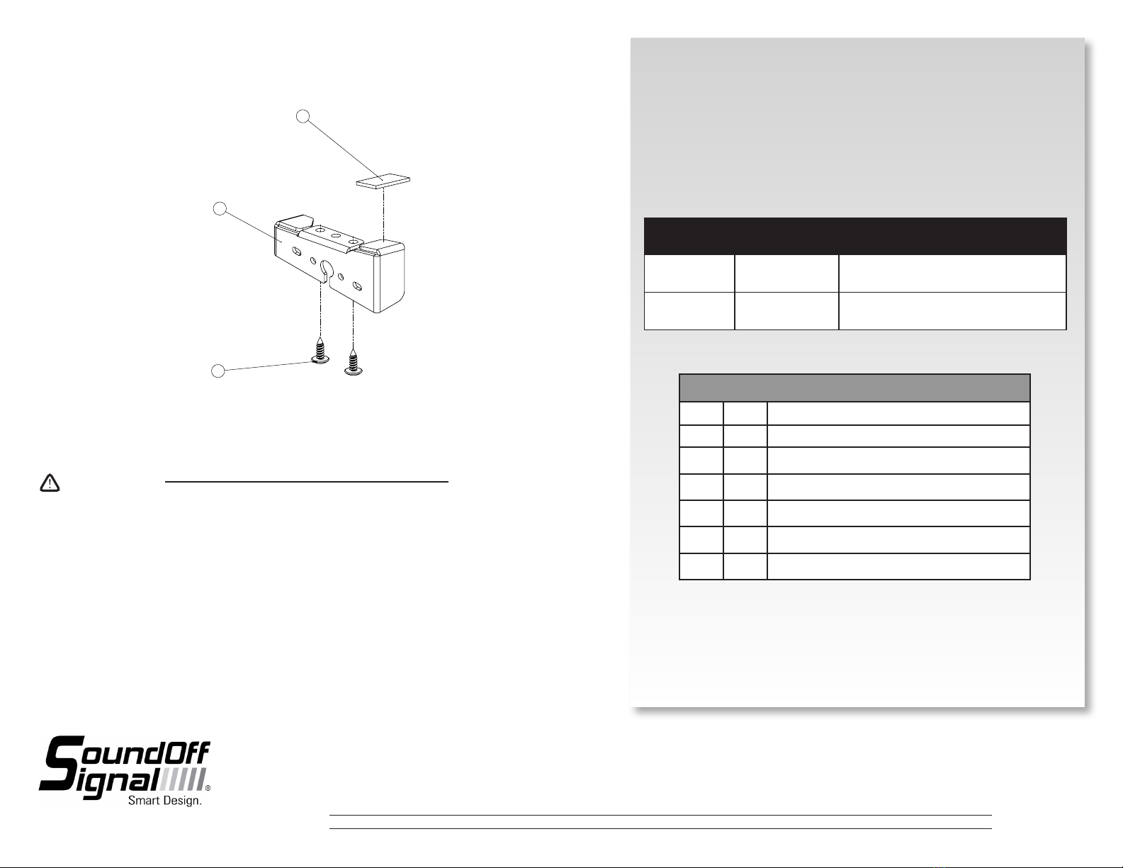
CONTENTS
ITEM# QTY COMPONENT
1 2 1” X 3” VHB TAPE
2 1 UNDERMIRROR 90 DEGREE BRACKET
3 2 #8 X .50 SM TRUSSHEAD PHILLIPS SCREW
1 SURFACE PREP WIPE
1 PRODUCT WARNING CARD
1 INSTRUCTION SHEET
INTRODUCTION:
mpower® Fascia Light Features:
• 3” Stud Mount and Quick Mount Options available for this bracket design
• Collaboration with Dow Corning® to develop ClearDuty™ optical design
• Greater resistance to gravel pitting, scratching, or cracking
• Improved sealing to prevent water from entering light
• Higher UV and thermal stability to prevent lens from yellowing over time
3
1
2
PMP2BKUMB2-P
NOTES:
1. CAD DATA IS MASTER
2. VOLUME = $PRPSHEET:{VOLUME MM} mm³
3. BREAK ALL SHARP EDGES, NO BURRS ALLOWED
4. GATE & EJECTOR LOCATIONS TO BE APPROVED
BY SOUNDOFF SIGNAL PRIOR TO TOOL BUILD
5. NO SUBSTITUTION OF MATERIAL ALLOWED WITHOUT
SOUNDOFF SIGNAL APPROVAL
6. VISIBLE SURFACES SHALL NOT HAVE EJECTION
PINS NOR GATE UNLESS APPROVED
7. POWDER COAT:
AKZO NOBEL TUX BLK U1576-2
INTERPON 200
PN243Q (22-7001)
THICKNESS: 2.5-4.0 MILS
PRETREAT: IRON PHOSPHATE
PMP2BKUMB2-D
Cover picture
CHARACTERISTIC NUMBERS
LAST USED
DELETED
KEY
REVISION LOG
REV
DESCRIPTION
INITIALS
ECN
DATE
1
01/01/1900
A A
B B
C C
D D
E E
F F
G G
H H
J J
K K
L L
14
14
13
13
12
12
11
11
10
10
9
9
8
8
7
7
6
6
5
5
4
4
3
3
2
2
1
1
CAD DIMENSIONS ARE BASIC
UNLESS OTHERWISE SPECIFIED
GD&T TO FOLLOW
ASME Y14.5M-2009
DRAWING NO:
D
PRIMARY DIMS:
INCH
DUAL DIMS: [mm]
TOLERANCES
EXCEPT AS NOTED
.X ± .020
.XX ± .012
.XXX ± .006
ANGLES ± .5°
DO NOT SCALE
DRAWING
SIZE:
SHEET
1 OF 5
DESCRIPTION:
REVISION:
®
PROPRIETARY AND CONFIDENTIAL
THE INFORMATION CONTAINED IN
THIS DRAWING IS THE SOLE
PROPERTY OF SOUNDOFF SIGNAL.
ANY REPRODUCTION IN PART OR
AS A WHOLE WITHOUT THE
WRITTEN PERMISSION OF
SOUNDOFF SIGNAL IS PROHIBITED.
THIRD ANGLE
PROJECTION
MATERIAL:
Test assembly undermirror
PMP2BKUMB2-P IS SHOWN*
*Installation instructions are for the passenger side bracket
(PMP2BKUMB2-P). Installation for the driver side is the same.
•HIGH CURRENT interconnects must be properly terminated. Poor crimp quality can cause heat
build-up and re. Follow crimp connector manufacturer instructions.
•DO NOT install this product or route any wires in the Air Bag Deployment Zone. Refer to vehicle
Owner’s Manual for deployment zones.
•Do NOT use system to disconnect headlights, brake lights or other safety equipment.
•Unit may become hot to touch during normal operation.
•Failure to properly install connectors, fuses or wiring may cause vehicle failure or re.
•Installation must only be performed by trained technician. Installer must determine vehicle wiring
conguration and proper integration of system.
•Use proper wire gauge. All power wires connecting to positive (+) or negative (-) battery terminal
or local chassis ground (-) must be sized to supply at least 125% of max. current and properly fused at
power source.
•Install protective grommets when routing wire through rewall or metal.
WARNING
1
2
3


