manuals.online logo
Brands
  1. Home
  2. •
  3. Brands
  4. •
  5. Teknik
  6. •
  7. Indoor Furnishing
  8. •
  9. Teknik Clifton Place 5421113 User manual

Teknik Clifton Place 5421113 User manual

www.teknikoffice.co.uk
Business or pleasure.
Works both ways.
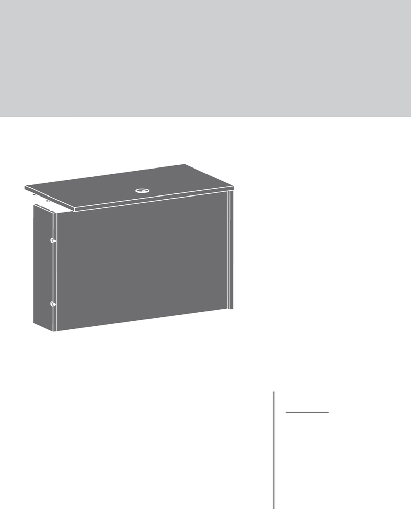
Executive Desk
Clifton Place Collection | Model 5421113
NOTE: THIS INSTRUCTION
BOOKLET CONTAINS IMPORTANT
SAFETY INFORMATION.
PLEASE READ AND KEEP FOR
FUTURE REFERENCE.
Teknik
Assembly Tools Required
Part Identification
Hardware Identification
Assembly Steps
Français
Español
Safety
Warranty
Hammer
Not actual size
No. 2 Phillips Screwdriver
Tip Shown Actual Size
Skip the power trip.
This time.
Table of Contents
2-3
3-4
5-38
39-43
44-48
49-50
51
Part Identification
A RIGHT END (1)
B LEFT END (1)
C LEFT UPRIGHT (1)
D RIGHT UPRIGHT (1)
E TOP (1)
F BACK (2)
G MODESTY PANEL (1)
H BOTTOM (2)
I SHORT TOP MOLDING (2)
J LONG TOP MOLDING (1)
K BRACE (4)
L BOTTOM MOLDING (4)
M FOOT (8)
N KEYBOARD SHELF (1)
O KEYBOARD HINGE FRONT (1)
P KEYBOARD FRONT (1)
Q SMALL DRAWER FRONT (2)
R DRAWER FRONT (2)
S LARGE DRAWER FRONT (2)
T SMALL LEFT DRAWER SIDE (2)
U SMALL DRAWER BACK (2)
V SMALL RIGHT DRAWER SIDE (2)
W LEFT DRAWER SIDE (2)
X DRAWER BACK (2)
Y RIGHT DRAWER SIDE (2)
Z LARGE LEFT DRAWER SIDE (2)
AA LARGE DRAWER BACK (2)
BB LARGE RIGHT DRAWER SIDE (2)
CC DRAWER BOTTOM (6)
DD MODESTY PANEL SHELF (1)
Page 2
Part Identification
åWhile not all parts are labeled, some of the parts will have a label or an inked letter on the edge
to help distinguish similar parts from each other. Use this part identification to help identify similar parts.
Now you know
our ABCs.
A
B
C
D
E
F
F
G
H
H
II
J
K
KK
K
L
LL
L
M
M
M
M
N
O
P
QQ
RR
S
S
T
T
U
U
V
V
W
W
X
X
Y
Y
Z
Z
AA
AA
BB
BB
CC
CC
CC
CC
CC
CC
DD
Hardware Identification
(EXTENSION SET SHOWN SEPARATED)
LONG EXTENSION
RAIL - 4
EE LONG EXTENSION
SLIDE - 4
FF
SHORT EXTENSION
RAIL - 2
GG SHORT EXTENSION
SLIDE - 2
HH
Page 3
Hardware Identification
åScrews are shown actual size. You may receive extra hardware with your unit.
ANGLED HEAD
CAM SCREW - 50
3STRAIGHT HEAD
CAM SCREW - 24
4
SMALL HIDDEN
CAM - 24
2
LARGE HIDDEN
CAM - 50
1
1/2" PAN HEAD SCREW - 36
20
LONG WOOD
DOWEL - 42
6
SILVER 1/2" FLAT HEAD SCREW - 16
19
BLACK 1/2" FLAT HEAD SCREW - 48
18
SHORT WOOD
DOWEL - 16
5
1-1/8" FLAT HEAD SCREW - 18
16
1-1/2" FLAT HEAD SCREW - 24
15
PULL - 6
11
HINGE - 2
8
FILE GLIDE - 4
13
9/16" WAFER HEAD SCREW - 2
17
CAM COVER
CARD - 1
14
LEVELER - 8
7GROMMET - 4
9GROMMET and
CAP - 2
10
FILE HANGER - 4
12
LEFT DRAWER
SLIDE - 4
LL
RIGHT DRAWER
SLIDE - 4
KK
LEFT CABINET
RAIL - 4
JJ
RIGHT CABINET
RAIL - 4
II
Page 4
QTY-26
COVERS
Angled head Straight head
Step 1
å Assemble your unit on a carpeted floor or on the empty carton to avoid scratching your unit or the floor.
å Turn six ANGLED HEAD CAM SCREWS (3) into the LEFT END (B).
å Push two LONG WOOD DOWELS (6) into the short edge of the LEFT END (B).
å Fasten two LEFT CABINET RAILS (JJ) to the LEFT END (B). Use six BLACK 1/2" FLAT HEAD SCREWS (18) through the
2nd, 3rd, and 5th holes as shown.
å Separate a LONG EXTENSION SLIDE (FF) from a LONG EXTENSION RAIL (EE) as shown in the upper diagram. Be
prepared, the parts are greasy.
å Fasten the LONG EXTENSION RAIL (EE) to the LEFT END (B). Use three 1/2" PAN HEAD SCREWS (20).
å NOTE: For each EXTENSION RAIL, turn a SCREW into the holes shown in the upper diagram. Then, slide the inner
cartridge of the EXTENSION RAIL in to find the other two holes that line up with the holes in the LEFT END. Turn the
SCREWS into those holes.
å NOTE: The LONG EXTENSION SLIDE will be used later for the LARGE DRAWERS.
6
Angled head
Open end
2
2
1
1
3
3
4
4
5
5
1/2" PAN HEAD SCREW
(3 used for the EXTENSION RAIL)
20
Roller end
3
BLACK 1/2" FLAT HEAD SCREW
(6 used for the CABINET RAILS)
18
Push the black lever down and pull the SLIDE from the RAIL.
EE
EE
FF
B
JJ
JJ
(6 used)
Page 5
Use this hole. Use these holes.
Step 2
å Turn six ANGLED HEAD CAM SCREWS (3) into the LEFT UPRIGHT (C).
å Fasten two RIGHT CABINET RAILS (II) to the LEFT UPRIGHT (C). Use six BLACK 1/2" FLAT HEAD SCREWS (18)
through the 2nd, 3rd, and 5th holes as shown.
å Separate a LONG EXTENSION SLIDE (FF) from a LONG EXTENSION RAIL (EE) as shown in the upper diagram. Be
prepared, the parts are greasy.
å Fasten the LONG EXTENSION RAIL (EE) to the LEFT UPRIGHT (C). Use three 1/2" PAN HEAD SCREWS (20).
å NOTE: For each EXTENSION RAIL, turn a SCREW into the hole shown in the upper diagram. Then, slide the inner
cartridge of the EXTENSION RAIL in to find the other two holes that line up with the holes in the LEFT UPRIGHT. Turn
the SCREWS into those holes.
å NOTE: The LONG EXTENSION SLIDE will be used later for the LARGE DRAWERS.
Angled head
Open end
2
2
1
1
3
3
4
4
5
5
1/2" PAN HEAD SCREW
(3 used for the EXTENSION RAIL)
20
Roller end
3
BLACK 1/2" FLAT HEAD SCREW
(6 used for the CABINET RAILS)
18
Push the black lever down and pull the SLIDE from the RAIL.
EE
EE
FF
C
II
II
(6 used)
Page 6
Use this hole. Use these holes.
Step 3
å Flip the LEFT UPRIGHT (C) over.
å Turn three ANGLED HEAD CAM SCREWS (3) into the LEFT UPRIGHT (C).
å Push two LONG WOOD DOWELS (6) into the short edge of the LEFT UPRIGHT (C).
å Separate a SHORT EXTENSION SLIDE (HH) from a SHORT EXTENSION RAIL (GG) as shown in the upper diagram.
Be prepared, the parts are greasy.
å Fasten the SHORT EXTENSION RAIL (GG) to the LEFT UPRIGHT (C). Use three 1/2" PAN HEAD SCREWS (20).
å NOTE: For each EXTENSION RAIL, turn a SCREW into the hole shown in the upper diagram. Then, slide the inner
cartridge of the EXTENSION RAIL in to find the other two holes that line up with the holes in the LEFT UPRIGHT. Turn
the SCREWS into those holes.
å NOTE: The SHORT EXTENSION SLIDE will be used later for the KEYBOARD SHELF.
å Insert a GROMMET (9) into the large hole in the LEFT UPRIGHT (C).
6
Angled head
Open end
1/2" PAN HEAD SCREW
(3 used for the EXTENSION RAIL)
20
3
Push the black lever down and pull the SLIDE from the RAIL.
C
9
GG HH
GG
Page 7
Use this hole. Use these holes.
Step 4
å Push fourteen LONG WOOD DOWELS (6) into a BACK (F), BOTTOM (H),
and two BRACES (K).
å Turn two ANGLED HEAD CAM SCREWS (3) into the BACK (F).
å Insert a GROMMET (9) into the large hole in the BOTTOM (H).
å Repeat this step for the other BACK (F), BOTTOM (H), and BRACES (K).
Angled head
3(4 used)
(2 used)
(28 used in this step)
6
6
6
6
6
9
F
H
K
K
Page 8
Step 5
(4 used in this step)
å Push two LARGE HIDDEN CAMS (1) into a BOTTOM (H).
å Fasten the BOTTOM (H) to a BACK (F). Tighten two
LARGE HIDDEN CAMS.
å NOTE: Be sure the WOOD DOWELS in the BOTTOM
insert into the BACK.
å Repeat this step for the other BACK (F), and BOTTOM (H).
F
H
Rounded edge
Surface with
HIDDEN CAMS
The CAM SCREWS
must be here.
3
21
1
The arrow must
point toward the
edge of the board.
1
Arrow
Page 9
Step 6
å Push six LARGE HIDDEN CAMS (1) into a BACK (F),
BOTTOM (H), and two BRACES (K).
å Fasten the LEFT END (B) to the BACK (F) and BOTTOM (H).
Tighten four LARGE HIDDEN CAMS.
å NOTE: Be sure the WOOD DOWELS in the BACK and
BOTTOM insert into the LEFT END.
å Fasten two BRACES (K) to the LEFT END (B). Tighten two
HIDDEN CAMS.
å NOTE: Be sure the WOOD DOWELS in the BRACES insert
into the LEFT END.
3
21
1
The arrow must
point toward the
edge of the board.
F
H
K
K
B
1
1
1
Arrow
Arrow
Arrow
Page 10
Step 7
å Push six LARGE HIDDEN CAMS (1) into the BACK (F),
BOTTOM (H), and BRACES (K).
å Fasten the LEFT UPRIGHT (C) to the BACK (F), BOTTOM (H),
and BRACES (K). Tighten six LARGE HIDDEN CAMS.
å NOTE: Be sure the WOOD DOWELS in the BACK, BOTTOM,
and BRACES insert into the LEFT UPRIGHT.
3
21
1
The arrow must
point toward the
edge of the board.
H
C
F
K
K
1
1
Page 11
Step 8
å Turn and tighten four FEET (M) into the BOTTOM (H).
H
M
M
M
M
Remember:
Righty tighty.
Lefty loosey.
Page 12
Step 9
å Push four SHORT WOOD DOWELS (5) into the BOTTOM (H).
å Fasten two BOTTOM MOLDINGS (L) to the BOTTOM (H). Use
four 1-1/8" FLAT HEAD SCREWS (16).
1-1/8" FLAT HEAD SCREW
(4 used in this step)
16
H
5
L
Page 13
L
5
Step 10
å Turn four LEVELERS (7) into the FEET (M).
å NOTE: The LEVELERS will be adjusted in the last step.
7
M
M
M
M
Page 14
Step 11
å Turn six ANGLED HEAD CAM SCREWS (3) into the RIGHT END (A).
å Push two LONG WOOD DOWELS (6) into the short edge of the RIGHT END (A).
å Fasten two RIGHT CABINET RAILS (II) to the RIGHT END (A). Use six BLACK 1/2" FLAT HEAD SCREWS (18) through the
2nd, 3rd, and 5th holes as shown.
å Separate a LONG EXTENSION SLIDE (FF) from a LONG EXTENSION RAIL (EE) as shown in the upper diagram. Be
prepared, the parts are greasy.
å Fasten the LONG EXTENSION RAIL (EE) to the RIGHT END (A). Use three 1/2" PAN HEAD SCREWS (20).
å NOTE: For each EXTENSION RAIL, turn a SCREW into the hole shown in the enlarged diagram. Then, slide the inner
cartridge of the EXTENSION RAIL in to find the other two holes that line up with the holes in the RIGHT END. Turn the
SCREWS into those holes.
å NOTE: The LONG EXTENSION SLIDE will be used later for the DRAWERS.
6
Angled head
Open end
2
2
1
1
3
3
4
4
5
5
1/2" PAN HEAD SCREW
(3 used for the EXTENSION RAIL)
20
Roller end
3
BLACK 1/2" FLAT HEAD SCREW
(6 used for the CABINET RAILS)
18
Push the black lever down and pull the SLIDE from the RAIL.
EE
EE
FF
A
(6 used)
II
II
Page 15
Use this hole. Use these holes.
Step 12
å Turn six ANGLED HEAD CAM SCREWS (3) into the RIGHT UPRIGHT (D).
å Fasten two LEFT CABINET RAILS (JJ) to the RIGHT UPRIGHT (D). Use six BLACK 1/2" FLAT HEAD SCREWS (18)
through the 2nd, 3rd, and 5th holes as shown.
å Separate a LONG EXTENSION SLIDE (FF) from a LONG EXTENSION RAIL (EE) as shown in the upper diagram. Be
prepared, the parts are greasy.
å Fasten the LONG EXTENSION RAIL (EE) to the RIGHT UPRIGHT (D). Use three 1/2" PAN HEAD SCREWS (20).
å NOTE: For each EXTENSION RAIL, turn a SCREW into the hole shown in the upper diagram. Then, slide the inner
cartridge of the EXTENSION RAIL in to find the other two holes that line up with the holes in the RIGHT UPRIGHT.
Turn the SCREWS into those holes.
å NOTE: The LONG EXTENSION SLIDE will be used later for the DRAWERS.
Angled head
Open end
1/2" PAN HEAD SCREW
(3 used for the EXTENSION RAIL)
20
Roller end
Push the black lever down and pull the SLIDE from the RAIL.
EE FF
D
3(6 used)
JJ
JJ
EE
Page 16
Use this hole. Use these holes.
2
2
1
1
3
34
4
5
5
BLACK 1/2" FLAT HEAD SCREW
(6 used for the CABINET RAILS)
18
Step 13
å Flip the RIGHT UPRIGHT (D) over.
å Turn three ANGLED HEAD CAM SCREWS (3) into the RIGHT UPRIGHT (D).
å Push two LONG WOOD DOWELS (6) into the short edge of the RIGHT UPRIGHT (D).
å Separate a SHORT EXTENSION SLIDE (HH) from a SHORT EXTENSION RAIL (GG) as shown in the upper diagram.
Be prepared, the parts are greasy.
å Fasten the SHORT EXTENSION RAIL (GG) to the RIGHT UPRIGHT (D). Use three 1/2" PAN HEAD SCREWS (20).
å NOTE: For each EXTENSION RAIL, turn a SCREW into the hole shown in the upper diagram. Then, slide the inner
cartridge of the EXTENSION RAIL in to find the other two holes that line up with the holes in the RIGHT UPRIGHT.
Turn the SCREWS into those holes.
å NOTE: The SHORT EXTENSION SLIDE will be used later for the KEYBOARD SHELF.
å Insert a GROMMET (9) into the large hole in the RIGHT UPRIGHT (D).
6
Angled head
Open end
1/2" PAN HEAD SCREW
(3 used for the EXTENSION RAIL)
20
Push the black lever down and pull the SLIDE from the RAIL.
D
9
GG HH
GG
3
Page 17
Use this hole. Use these holes.
Step 14
å Push six LARGE HIDDEN CAMS (1) into a BACK (F),
BOTTOM (H), and two BRACES (K).
å Fasten the RIGHT END (A) to the BACK (F) and BOTTOM (H).
Tighten four LARGE HIDDEN CAMS.
å NOTE: Be sure the WOOD DOWELS in the BACK and
BOTTOM insert into the RIGHT END.
å Fasten two BRACES (K) to the RIGHT END (A). Tighten two
HIDDEN CAMS.
å NOTE: Be sure the WOOD DOWELS in the BRACES insert
into the RIGHT END.
3
21
1
The arrow must
point toward the
edge of the board.
K
K
A
H
F
1
1
Page 18
Step 15
å Push six LARGE HIDDEN CAMS (1) into the BACK (F),
BOTTOM (H), and BRACES (K).
å Fasten the RIGHT UPRIGHT (D) to the BACK (F),
BOTTOM (H), and BRACES (K). Tighten six LARGE
HIDDEN CAMS.
å NOTE: Be sure the WOOD DOWELS in the BACK,
BOTTOM, and BRACES insert into the RIGHT UPRIGHT.
3
21
1
The arrow must
point toward the
edge of the board.
H
D
K
K
F
1
1
Page 19
Step 16
å Turn and tighten four FEET (M) into the BOTTOM (H).
å Push four SHORT WOOD DOWELS (5) into the BOTTOM (H).
å Fasten two BOTTOM MOLDINGS (L) to the BOTTOM (H). Use
four 1-1/8" FLAT HEAD SCREWS (16).
H
H
M
M
M
M
1-1/8" FLAT HEAD SCREW
(4 used for the MOLDINGS)
16
5
5
L
L
Page 20

Other Teknik Indoor Furnishing manuals

Teknik Elstree Executive Desk 5426918 User manual

Teknik

Teknik Elstree Executive Desk 5426918 User manual

Teknik Hampstead Park  Narrow Bookcase 5420283 User manual

Teknik

Teknik Hampstead Park Narrow Bookcase 5420283 User manual

Teknik Boulevard Cafe 5420650 User manual

Teknik

Teknik Boulevard Cafe 5420650 User manual

Teknik Home Study 5426616 User manual

Teknik

Teknik Home Study 5426616 User manual

Teknik Avon 5422051 User manual

Teknik

Teknik Avon 5422051 User manual

Teknik 5427428 User manual

Teknik

Teknik 5427428 User manual

Teknik 5431262 User manual

Teknik

Teknik 5431262 User manual

Teknik Boulevard Cafe 5427345 User manual

Teknik

Teknik Boulevard Cafe 5427345 User manual

Teknik Hudson Elm Finish 5427424 User manual

Teknik

Teknik Hudson Elm Finish 5427424 User manual

Teknik 5421120 User manual

Teknik

Teknik 5421120 User manual

Teknik Canyon Lane 5425302 User manual

Teknik

Teknik Canyon Lane 5425302 User manual

Teknik Hudson 5425825 User manual

Teknik

Teknik Hudson 5425825 User manual

Teknik 5427873 User manual

Teknik

Teknik 5427873 User manual

Teknik Craft 5427456 User manual

Teknik

Teknik Craft 5427456 User manual

Teknik CUBE RECEPTION CHAIR MODULAR UNIT User manual

Teknik

Teknik CUBE RECEPTION CHAIR MODULAR UNIT User manual

Teknik 5420649 User manual

Teknik

Teknik 5420649 User manual

Teknik Boulevard Cafe Desk 5420701 User manual

Teknik

Teknik Boulevard Cafe Desk 5420701 User manual

Teknik Elstree L-Shaped Desk 5426914 User manual

Teknik

Teknik Elstree L-Shaped Desk 5426914 User manual

Teknik 5418793 User manual

Teknik

Teknik 5418793 User manual

Teknik Executive Trestle Desk 5424128 User manual

Teknik

Teknik Executive Trestle Desk 5424128 User manual

Teknik 5427427 User manual

Teknik

Teknik 5427427 User manual

Teknik Lux Desk 5426429 User manual

Teknik

Teknik Lux Desk 5426429 User manual

Teknik Boutique Style Desk User manual

Teknik

Teknik Boutique Style Desk User manual

Teknik Market 5425767 User manual

Teknik

Teknik Market 5425767 User manual

Popular Indoor Furnishing manuals by other brands

Atmos 21 D operating instructions

Atmos

Atmos 21 D operating instructions

Furniture of America CM6495 Assembly instructions

Furniture of America

Furniture of America CM6495 Assembly instructions

Ilva GAIN 1069668 Assembly instruction

Ilva

Ilva GAIN 1069668 Assembly instruction

Health Care Logistics 1431 instructions

Health Care Logistics

Health Care Logistics 1431 instructions

Bell'O AVSC2155 Assembly instructions

Bell'O

Bell'O AVSC2155 Assembly instructions

Diagone E04 manual

Diagone

Diagone E04 manual

Hillsdale Furniture 101845−104852 quick start guide

Hillsdale Furniture

Hillsdale Furniture 101845−104852 quick start guide

Sonorous SP 600 Assembly instructions

Sonorous

Sonorous SP 600 Assembly instructions

Lorell 60500 Assembly instructions

Lorell

Lorell 60500 Assembly instructions

Galipette 405 manual

Galipette

Galipette 405 manual

Desalto SKIN ALLUNGABILE Assembly instruction

Desalto

Desalto SKIN ALLUNGABILE Assembly instruction

Sauder Palladia 411830 manual

Sauder

Sauder Palladia 411830 manual

VIPACK AMORI AMHB9014 Assembly instructions

VIPACK

VIPACK AMORI AMHB9014 Assembly instructions

Vente Unique AZIDEE-LHF Product description

Vente Unique

Vente Unique AZIDEE-LHF Product description

Pride Lift Chair Series owner's manual

Pride

Pride Lift Chair Series owner's manual

modway EEI-4895 Assembly instructions

modway

modway EEI-4895 Assembly instructions

Coaster 206391KE Assembly instructions

Coaster

Coaster 206391KE Assembly instructions

LIMAL VTS-485E Assembly instructions

LIMAL

LIMAL VTS-485E Assembly instructions

manuals.online logo
manuals.online logoBrands
  • About & Mission
  • Contact us
  • Privacy Policy
  • Terms and Conditions

Copyright 2025 Manuals.Online. All Rights Reserved.