manuals.online logo
Brands
  1. Home
  2. •
  3. Brands
  4. •
  5. Teknik
  6. •
  7. Indoor Furnishing
  8. •
  9. Teknik 5423912 User manual

Teknik 5423912 User manual

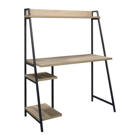
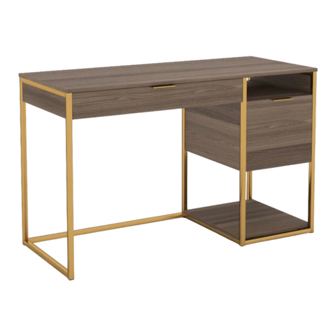
Steel Gorge Desk
Model 5423912
NOTE: THIS INSTRUCTION
BOOKLET CONTAINS IMPORTANT
SAFETY INFORMATION.
PLEASE READ AND KEEP FOR
FUTURE REFERENCE.
Sit and surf.
Teknik
www.teknikoffice.co.uk
Table of Contents Assembly Tools Required
3
4
5-28
37-38
39
Part Identification
Hardware Identification
Assembly Steps
Safety
Warranty
No. 2 Phillips Screwdriver
Tip Shown Actual Size
Skip the power trip.
This time.
Page 2
Part Identification
åWhile not all parts are labeled, some of the parts will have a label or an inked letter on the edge
to help distinguish similar parts from each other. Use this part identification to help identify similar parts.
A RIGHT LEG (1)
B LEFT LEG (1)
C CENTER LEG (1)
D TOP (1)
E RIGHT END (1)
F CENTER END (1)
G CENTER UPRIGHT (1)
H LEFT UPRIGHT (1)
I BACK (1)
J LARGE BACK (1)
K SHELF (1)
L LARGE EXTENSION BLOCK (2)
M SMALL EXTENSION BLOCK (2)
N BRACE (1)
O LONG BRACE (2)
P SHORT BRACE (2)
Q LARGE DRAWER RIGHT SIDE (1)
R LARGE DRAWER LEFT SIDE (1)
S LARGE DRAWER BACK (1)
T LARGE DRAWER BOTTOM (1)
U DRAWER RIGHT SIDE (1)
V DRAWER LEFT SIDE (1)
W DRAWER BACK (1)
X DRAWER BOTTOM (1)
Y DRAWER BRACE (1)
Z DRAWER FRONT (1)
AA LARGE DRAWER FRONT (1)
Now you know
our ABCs.
Page 3
A
B
C
D
E
F
G
H
I
J
K
N
O
P
Q
R
S
T
U
V
WX
Y
Z
AA
O
M
L
P
ML
Hardware Identification
åScrews are shown actual size. You may receive extra hardware with your unit.
BLACK 1-3/4" PAN HEAD SCREW - 10
13 BLACK 1" PAN HEAD SCREW - 4
14
BLACK 1" FLAT HEAD SCREW - 8
15
BLACK 1/2" FLAT HEAD SCREW - 12
19
BLACK 5/16" MACHINE SCREW - 1
21
BLACK 11/16" FLAT HEAD SCREW - 4
16
BLACK 1/2" PAN HEAD SCREW - 22
18
BLACK 1/2" MACHINE SCREW - 4
20
NUT - 1
11
WOOD DOWEL - 4
8
METAL BRACKET - 6
9TOOL - 1
12
Page 4
HIDDEN CAM - 12
5SMALL HIDDEN
CAM - 12
6CAM SCREW - 24
7
4EXTENSION SLIDE - 2
3EXTENSION RAIL - 2
(EXTENSION SET SHOWN SEPARATED)
1LEFT RAIL - 1 2RIGHT RAIL - 1
KNOB SET - 2
10 BUMPER
CARD - 1
22
BLACK 1" MACHINE SCREW - 2
23
Step 1
å Assemble your unit on a carpeted floor or on the empty
carton to avoid scratching your unit or the floor.
å Fasten the LEFT LEG (B) to the LEFT UPRIGHT (H). Use
two BLACK 1-3/4" PAN HEAD SCREWS (13) and two
BLACK 1/2" PAN HEAD SCREWS (18).
Page 5
BLACK 1/2" PAN HEAD SCREW
(2 used in this step)
18
Edge with holes
Surface with holes
BLACK 1-3/4" PAN HEAD SCREW
(2 used in this step)
13
B
H
Holes facing up
Step 2
å Fasten the LEFT RAIL (1) and one of the SMALL
EXTENSION BLOCKS (M) to the LEFT UPRIGHT (H)
exactly as shown. Use two BLACK 11/16" FLAT
HEAD SCREWS (16).
å NOTE: Find the back hole first. Then, slide the inner
cartridge of the LEFT RAIL in to find the other hole that
lines up with the hole in the SMALL EXTENSION BLOCK
and LEFT UPRIGHT. Turn a SCREW into this hole.
å NOTE: You should start each SCREW a few turns before
completely tightening any of them.
Page 6
BLACK 11/16" FLAT HEAD SCREW
(2 used in this step)
16
H
M
1
These edges
should be even.
This hole is closer
to this edge.
Line up the
back hole first.
Finished surface
1
Holes facing up
å Fasten four METAL BRACKETS (9) to the CENTER
LEG (C) exactly as shown. Use four BLACK 1/2" PAN
HEAD SCREWS (18).
Step 3
Page 7
BLACK 1/2" PAN HEAD SCREW
(4 used in this step)
18
C
9
Step 4
å Fasten the CENTER LEG (C) to the CENTER END (F) and
CENTER UPRIGHT (G). Use four BLACK 1/2" PAN HEAD
SCREWS (18) through the METAL BRACKETS on the CENTER
LEG and into the CENTER END and CENTER UPRIGHT.
å Finish fastening the CENTER LEG (C) to the CENTER END (F)
and CENTER UPRIGHT (G). Use four BLACK 1-3/4" PAN
HEAD SCREWS (13).
å Turn two CAM SCREWS (7) into the CENTER END (F).
Page 8
BLACK 1/2" PAN HEAD SCREW
(4 used in this step)
18
BLACK 1-3/4" PAN HEAD SCREW
(4 used in this step)
13
G
C
F
Surface with holes
Surface with
fewer holes
Edge without holes
7
å Fasten one of the LARGE EXTENSION BLOCKS (L) to the
CENTER END (F). Use two BLACK 1" PAN HEAD SCREWS (14)
in the outer holes.
Step 5
Page 9
F
L
C
Surface with
more holes
This hole is closer
to this edge.
BLACK 1" PAN HEAD SCREW
(2 used in this step)
14
Step 6
å Carefully flip the CENTER LEG (C) over.
å Fasten the RIGHT RAIL (2) and the remaining SMALL
EXTENSION BLOCK (M) to the CENTER UPRIGHT (G) exactly
as shown. Use two BLACK 11/16" FLAT HEAD SCREWS (16).
å NOTE: Find the back hole first. Then, slide the inner cartridge
of the RIGHT RAIL in to find the other hole that lines up with
the hole in the SMALL EXTENSION BLOCK and CENTER
UPRIGHT. Turn a SCREW into this hole.
Page 10
C
BLACK 11/16" FLAT HEAD SCREW
(2 used in this step)
16
M
These edges
should be even.
This hole is closer
to this edge.
Line up the
back hole first.
Finished surface
2
G
2
Step 7
Page 11
å Fasten two METAL BRACKETS (9) to the RIGHT
LEG (A) exactly as shown. Use two BLACK 1/2" PAN
HEAD SCREWS (18).
BLACK 1/2" PAN HEAD SCREW
(2 used in this step)
18
A
9
Step 8
å Fasten the RIGHT LEG (A) to the RIGHT END (E). Use two
BLACK 1/2" PAN HEAD SCREWS (18) through the METAL
BRACKETS on the RIGHT LEG and into the RIGHT END.
å Finish fastening the RIGHT LEG (A) to the RIGHT END (E).
Use two BLACK 1-3/4" PAN HEAD SCREWS (13).
Page 12
A
BLACK 1/2" PAN HEAD SCREW
(2 used in this step)
18
BLACK 1-3/4" PAN HEAD SCREW
(2 used in this step)
13
E
Surface
with
holes
Edge without holes
å Fasten the remaining LARGE EXTENSION BLOCK (L)
to the RIGHT END (E). Use two BLACK 1" PAN HEAD
SCREWS (14) in the outer holes.
Step 9
Page 13
Surface with
more holes
This hole is closer
to this edge.
BLACK 1" PAN HEAD SCREW
(2 used in this step)
14
E
A
L
Step 10
å Separate the EXTENSION SLIDES (4) from the EXTENSION RAILS (3) as
shown in the enlarged diagram below. Be prepared, the parts are greasy.
å Fasten the EXTENSION RAILS (3) to the LARGE EXTENSION BLOCKS (L).
Use four BLACK 1/2" FLAT HEAD SCREWS (19).
å NOTE: For each EXTENSION RAIL, turn a SCREW into the back hole. Then,
slide the inner cartridge of the EXTENSION RAIL in to find the other hole that
lines up with the hole in the LARGE EXTENSION BLOCK. Turn a SCREW into
this hole.
å NOTE: The EXTENSION SLIDES will be used later for the LARGE DRAWER.
Page 14
Push up on the black lever and pull the SLIDE from the RAIL.
A
C
L
L
4
3
3
3
3
BLACK 1/2" FLAT HEAD SCREW
(4 used in this step)
19
G
Use these holes.
Open end
Open end
Open end
Back hole
Back hole
å Separate the BLACK 1/2" MACHINE SCREWS (17 and 20). Use
the thicker SCREW (20) in this step.
å Turn two CAM SCREWS (7) into the RIGHT END (E).
å Insert two SMALL HIDDEN CAMS (6) into the LARGE BACK (J).
å Fasten the LARGE BACK (J) to the RIGHT END (E). Tighten two
HIDDEN CAMS.
å Fasten the SHORT BRACES (P) to the RIGHT LEG (A). Use two
BLACK 1/2" MACHINE SCREWS (20).
Step 11
Page 15
7
E
J
A
P
3
21
6
The arrow must
point toward the
edge of the board.
6
BLACK 1/2" MACHINE SCREW
(2 used for the SHORT BRACES)
20
These edges
should be even.
These edges
should be even.
Surface
with holes
Surface without holes
P
Step 12
å Insert two SMALL HIDDEN CAMS (6) into the LARGE BACK (J).
å Fasten the CENTER END (F) to the LARGE BACK (J). Tighten
two HIDDEN CAMS.
å Fasten the CENTER LEG (C) to the SHORT BRACES (P). Use
two BLACK 1/2" MACHINE SCREWS (20).
Page 16
3
21
6
The arrow must
point toward the
edge of the board.
J
P
6
BLACK 1/2" MACHINE SCREW
(2 used for the SHORT BRACES)
20
P
C
F
å Carefully stand your unit upright.
å Turn four CAM SCREWS (7) into the SHELF (K).
å Insert four HIDDEN CAMS (5) into the ENDS (E and F).
å Fasten the SHELF (K) to the ENDS (E and F). Tighten four
HIDDEN CAMS.
Step 13
Page 17
3
21
5
The arrow must
point toward the
edge of the board.
E
F
K
K
Surface
with holes
5
5
7
You may need to loosen
these SCREWS to position
the SHELF in place.
Step 14
å Turn two CAM SCREWS (7) into the LEFT UPRIGHT (H).
å Insert two HIDDEN CAMS (5) into the BACK (I).
å Fasten the BACK (I) to the LEFT UPRIGHT (H). Tighten
two HIDDEN CAMS.
å Fasten the BRACE (N) to the LEFT LEG (B). Use two
BLACK 1/2" PAN HEAD SCREWS (18).
Page 18
3
21
5
The arrow must
point toward the
edge of the board.
N
B
I
H
N
BLACK 1/2" PAN HEAD SCREW
(2 used for the BRACE)
18
5
7
Finished edge
Surface with holes
å Carefully stand the LEFT LEG (B) upright.
å Turn two CAM SCREWS (7) into the CENTER UPRIGHT (G).
å Insert two HIDDEN CAMS (5) into the BACK (I).
å Fasten the BACK (I) to the CENTER UPRIGHT (G). Tighten
two HIDDEN CAMS.
å Fasten the BRACE (N) to the CENTER LEG (C). Use two
BLACK 1/2" PAN HEAD SCREWS (18).
Step 15
Page 19
BLACK 1/2" PAN HEAD SCREW
(2 used for the BRACE)
18
3
21
5
The arrow must
point toward the
edge of the board.
5
7
N
I
C
G
B
Step 16
å Turn four CAM SCREWS (7) into the TOP (D).
å Insert four HIDDEN CAMS (5) into the UPRIGHTS (G and H).
å Fasten the TOP (D) to the UPRIGHTS (G and H). Tighten four
HIDDEN CAMS.
å Fasten the TOP (D) to the RIGHT LEG (A). Use two BLACK
1-3/4" PAN HEAD SCREWS (13).
Page 20
3
21
5
The arrow must
point toward the
edge of the board.
Surface
with holes
H
G
D
A
BLACK 1-3/4" PAN HEAD SCREW
(2 used for the RIGHT LEG)
13
D
7
7
5

Other Teknik Indoor Furnishing manuals
Teknik CUBE RECEPTION CHAIR MODULAR UNIT User manual

Teknik

Teknik CUBE RECEPTION CHAIR MODULAR UNIT User manual

Teknik Boulevard Cafe 5421950 User manual

Teknik

Teknik Boulevard Cafe 5421950 User manual

Teknik 5414142 User manual

Teknik

Teknik 5414142 User manual

Teknik Spanish Style Desk 5420114 User manual

Teknik

Teknik Spanish Style Desk 5420114 User manual

Teknik Elstree 5426908 User manual

Teknik

Teknik Elstree 5426908 User manual

Teknik Credenza 5421317 User manual

Teknik

Teknik Credenza 5421317 User manual

Teknik 5427872 User manual

Teknik

Teknik 5427872 User manual

Teknik Trestle 5410421 User manual

Teknik

Teknik Trestle 5410421 User manual

Teknik Canal Heights 5419228 User manual

Teknik

Teknik Canal Heights 5419228 User manual

Teknik Barrister Home 5420176 User manual

Teknik

Teknik Barrister Home 5420176 User manual

Teknik 5420173 User manual

Teknik

Teknik 5420173 User manual

Teknik Boutique Style Desk User manual

Teknik

Teknik Boutique Style Desk User manual

Teknik 5420276 User manual

Teknik

Teknik 5420276 User manual

Teknik 5426135 User manual

Teknik

Teknik 5426135 User manual

Teknik 5414873 User manual

Teknik

Teknik 5414873 User manual

Teknik 5412885 User manual

Teknik

Teknik 5412885 User manual

Teknik 5427030 User manual

Teknik

Teknik 5427030 User manual

Teknik Barrister Home 5418705 User manual

Teknik

Teknik Barrister Home 5418705 User manual

Teknik Office Affiliate 5427468 User manual

Teknik

Teknik Office Affiliate 5427468 User manual

Teknik 5423023 User manual

Teknik

Teknik 5423023 User manual

Teknik 5431916 User manual

Teknik

Teknik 5431916 User manual

Teknik 5158097 User manual

Teknik

Teknik 5158097 User manual

Teknik Streamline L-Shaped Desk 5414417 User manual

Teknik

Teknik Streamline L-Shaped Desk 5414417 User manual

Teknik Barrister Home 4 Drawer Chest User manual

Teknik

Teknik Barrister Home 4 Drawer Chest User manual

Popular Indoor Furnishing manuals by other brands

Kvik T530,060 Assembly instruction

Kvik

Kvik T530,060 Assembly instruction

HULALA HOME SCCL0360 Assembly instructions

HULALA HOME

HULALA HOME SCCL0360 Assembly instructions

CB2 chill Assembly manual

CB2

CB2 chill Assembly manual

WATSON 360.394.1300 Assembly

WATSON

WATSON 360.394.1300 Assembly

Hülsta now! 4133 Assembly instructions

Hülsta

Hülsta now! 4133 Assembly instructions

MACMILANO SHELVIO CAPITAN MCM022003 Series quick start guide

MACMILANO

MACMILANO SHELVIO CAPITAN MCM022003 Series quick start guide

Next SLOANE BED 887928 Assembly instructions

Next

Next SLOANE BED 887928 Assembly instructions

Songmics KSC01 manual

Songmics

Songmics KSC01 manual

Songmics VASAGLE XLLS21 manual

Songmics

Songmics VASAGLE XLLS21 manual

Furniture of America CM7966-EK Assembly instructions

Furniture of America

Furniture of America CM7966-EK Assembly instructions

Mocka Portia Console Table Assembly instructions

Mocka

Mocka Portia Console Table Assembly instructions

Cooper Lighting Cambria 403 Specification sheet

Cooper Lighting

Cooper Lighting Cambria 403 Specification sheet

UDIZINE Palo System IPSK002 installation instructions

UDIZINE

UDIZINE Palo System IPSK002 installation instructions

Sensea PERLA 47 S 110 2T 1P Assembly, Use, Maintenance Manual

Sensea

Sensea PERLA 47 S 110 2T 1P Assembly, Use, Maintenance Manual

BLACK RED WHITE re set atol 8/11 Assembly manual

BLACK RED WHITE

BLACK RED WHITE re set atol 8/11 Assembly manual

DREAMS Single bed Assembly instructions

DREAMS

DREAMS Single bed Assembly instructions

Dorel Living DA8050-A manual

Dorel Living

Dorel Living DA8050-A manual

Mocka Eclipse Assembly instructions

Mocka

Mocka Eclipse Assembly instructions

manuals.online logo
manuals.online logoBrands
  • About & Mission
  • Contact us
  • Privacy Policy
  • Terms and Conditions

Copyright 2025 Manuals.Online. All Rights Reserved.