manuals.online logo
Brands
  1. Home
  2. •
  3. Brands
  4. •
  5. Teknik
  6. •
  7. Indoor Furnishing
  8. •
  9. Teknik 5414142 User manual

Teknik 5414142 User manual

NOTE: THIS INSTRUCTION
BOOKLET CONTAINS IMPORTANT
SAFETY INFORMATION.
PLEASE READ AND KEEP FOR
FUTURE REFERENCE.
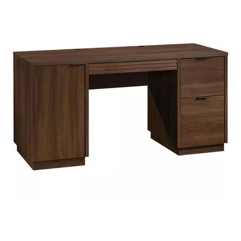
Computer Desk
5414142 Cobblestone Grey
5414141 Cottage Green
5414693 Sherbet Yellow
Sit and surf.
Teknik
www.teknikoffice.co.uk
Table of Contents Assembly Tools Required
2-3
4
5-28
29-32
33-36
37-38
39
Part Identification
Hardware Identification
Assembly Steps
Français
Español
Safety
Warranty
Hammer
Not actual size
No. 2 Phillips Screwdriver
Tip Shown Actual Size
Skip the power trip.
This time.
Page 2
Part Identification
åWhile not all parts are labeled, some of the parts will have a label or an inked letter on the edge
to help distinguish similar parts from each other. Use this part identification to help identify similar parts.
A RIGHT END (1)
B LEFT END (1)
C UPRIGHT (1)
D TOP (1)
E BOTTOM (2)
F MODESTY PANEL (1)
G SHELF (1)
H BACK (1)
I
LEFT FRONT/RIGHT BACK LEG (3)
J
RIGHT FRONT/LEFT BACK LEG (3)
K SMALL DRAWER FRONT (1)
O LARGE DRAWER FRONT (1)
Q PENCIL DRAWER FRONT (1)
T SKIRT (1)
U LOWER END MOLDING (3)
V PENCIL DRAWER MOLDING (1)
W DRAWER MOLDING (1)
X EXTENSION BLOCK (1)
D102 LARGE DRAWER SIDE (2)
D112 LARGE DRAWER FRONT/BACK (2)
D113 DRAWER SIDE (4)
D114 SMALL DRAWER FRONT/BACK (2)
D116
PENCIL DRAWER FRONT/BACK (2)
D713 DRAWER BOTTOM (2)
D722 LARGE DRAWER BOTTOM (1)
Part Identification Now you know
our ABCs.
Page 3
A
B
C
D
E
E
F
G
H
I
I
I
J
J
J
T
U
U
U
X
D116
D116
D113
D113
D722
Q
V
D113
D113 D114
D114
D713
K
W
D112
D112
D102
D102
D713
O
Hardware Identification
åScrews are shown actual size. You may receive extra hardware with your unit.
Page 4
ZEXTENSION SLIDE - 2
YEXTENSION RAIL - 2
(EXTENSION SET SHOWN SEPARATED)
FILE GLIDE - 2
3B
HIDDEN CAM - 36
1F CAM SCREW - 18
8F
BLACK 1-7/8" FLAT HEAD SCREW - 7
2S
GOLD 5/16" FLAT HEAD SCREW - 24
3S
KNOB - 3
63K
BLACK 1-5/8" PAN HEAD SCREW - 3
27S
BLACK 9/16" LARGE HEAD SCREW - 4
1S
METAL PIN - 4
1R
CAM DOWEL - 18
2F
BLACK 9/16" FLAT HEAD SCREW - 6
32S
BLACK 1-1/4" FLAT HEAD SCREW - 2
7S
NAIL - 25
1N
BLACK 7/8" LARGE HEAD SCREW - 10
17S
CAM COVER - 5
33P
19G LARGE METAL
BRACKET - 2
40CA CABINET RIGHT - 2 40CB CABINET LEFT - 2 40CC DRAWER RIGHT - 2 40CD DRAWER LEFT - 2
30S BLACK 1-9/16" FLAT HEAD SCREW - 24
Step 1
å Assemble your unit on a carpeted floor or on the empty carton to
avoid scratching your unit or the floor.
å Push thirty-six HIDDEN CAMS (1F) into the ENDS (A and B),
UPRIGHT (C), BOTTOMS (E), MODESTY PANEL (F) and
SHELF (G). Then, insert the metal end of a CAM DOWEL (2F)
into each HIDDEN CAM, except the long edges of the ENDS ( A
and B) and UPRIGHT (C).
Page 5
A
B
C
F
G
E
E
Arrow
1F
2F
Do not tighten the HIDDEN CAMS in this step.
Do not insert
CAM DOWELS
into these edges.
Insert the metal end of the CAM
DOWEL into the HIDDEN CAM.
Arrow
Arrow
The arrow in the HIDDEN
CAM must point toward the
hole in the edge of the board.
Hole
(36 used)
1F
2F
Arrow
(18 used)
Step 2
å Turn eighteen CAM SCREWS (8F) into the LEGS (I and J).
Page 6
8F
I
I
I
J
J
J
Remember:
Righty tighty.
Lefty loosey.
(18 used)
å Fasten two LEFT FRONT LEGS (I) to the LEFT END (B)
and UPRIGHT (C). Tighten six HIDDEN CAMS.
å Fasten a RIGHT FRONT LEG (J) to the RIGHT END (A).
Tighten three HIDDEN CAMS.
Step 3
Page 7
B
C
A
J
I
I
These edges
should be even.
Surface with
HIDDEN CAMS
Surface with
HIDDEN CAMS
Surface with
HIDDEN CAMS
These edges
should be even.
1
2
Step 4
å Flip the ENDS (A and B) and UPRIGHT (C) over onto their
opposite surface.
å Turn six BLACK 9/16" FLAT HEAD SCREWS (32S) into
the ENDS (A and B) and UPRIGHT (C) until the shoulders
of the SCREWS rest on the surface of each one.
å Slide the LOWER END MOLDINGS (U) onto the ENDS and
UPRIGHT. Line up the grooves in the MOLDINGS over the
heads of the SCREWS in the ENDS and UPRIGHT.
Page 8
B
C
A
U
U
U
These edges
should be even.
These edges
should be even.
These edges
should be even.
Apply pressure with your hands as
you guide the MOLDINGS over the
SCREWS and onto the ENDS.
Shoulder
BLACK 9/16" FLAT HEAD SCREW
(6 used in this step)
32S
å Flip the ENDS (A and B) and UPRIGHT (C) over onto their
opposite surface.
å Fasten two RIGHT FRONT/LEFT BACK LEGS (J) to the LEFT
END (B) and UPRIGHT (C). Tighten six HIDDEN CAMS.
å Fasten a LEFT FRONT/RIGHT BACK LEG (I) to the RIGHT
END (A). Tighten three HIDDEN CAMS.
Step 5
Page 9
B
C
A
J
J
I
These edges
should be even.
These edges
should be even.
Surface with
HIDDEN CAMS
Surface with
HIDDEN CAMS
Surface with
HIDDEN CAMS
Step 6
å Separate the EXTENSION SLIDES (Z) from the EXTENSION RAILS (Y)
as shown in the upper diagram below. Be prepared, the parts are greasy.
å Fasten an EXTENSION RAIL (Y) to the RIGHT END (A) and UPRIGHT (C).
Use four GOLD 5/16" FLAT HEAD SCREWS (3S).
å NOTE: For each EXTENSION RAIL, turn a SCREW into the hole shown in
the enlarged diagram. Then, slide the inner cartridge of the EXTENSION
RAIL in to find the other hole that lines up with the hole in the END and
UPRIGHT. Turn a SCREW into this hole.
Page 10
C
A
Push the black lever in and pull the SLIDE from the RAIL.
Y
Y
Y
Z
Open end
Open end
GOLD 5/16" FLAT HEAD SCREW
(4 used in this step)
3S
Edge with CAM DOWELS
Surface with
HIDDEN CAMS
Surface with
HIDDEN CAMS
å Fasten a CABINET RIGHT (40CA) to the RIGHT END (A)
and a CABINET LEFT (40CB) to the UPRIGHT (C) and
LEFT END (B). Use six GOLD 5/16" FLAT HEAD
SCREWS (3S) through holes #1 and #3.
Step 7
Page 11
C
A
B
GOLD 5/16" FLAT HEAD SCREW
(6 used in this step)
3S
1
2
3
4
1
2
34
Roller end
Roller end
1
2
34
Roller end
Step 8
å Flip the UPRIGHT (C) over onto its opposite surface.
å Fasten the EXTENSION BLOCK (X) to the UPRIGHT (C).
Use two BLACK 1-1/4" FLAT HEAD SCREWS (7S).
å Fasten the CABINET RIGHT (40CA) to the EXTENSION
BLOCK (X). Use two GOLD 5/16" FLAT HEAD
SCREWS (3S) through holes #1 and #3.
Page 12
C
X
1
2
3
4
Roller end
Finished edge
BLACK 1-1/4" FLAT HEAD SCREW
(2 used for the EXTENSION BLOCK)
7S
GOLD 5/16" FLAT HEAD SCREW
(2 used for the RAIL)
3S
å Fasten the MODESTY PANEL (F) to the LEFT END (B).
Tighten two HIDDEN CAMS.
Step 9
Page 13
B
F
Start Tighten
Arrow
Minimum
190 degrees
Caution
Risk of damage or
injury. HIDDEN CAMS
must be completely
tightened. HIDDEN
CAMS that are not
completely tightened
may loosen, and parts
may separate. To
completely tighten:
Arrow
Maximum
210 degrees
Surface
with
HIDDEN
CAMS
Curved edge
Now might be a
good time to refresh
your drink.
Step 10
å Fasten the MODESTY PANEL (F) and LEFT END (B) to the
TOP (D). Tighten four HIDDEN CAMS.
Page 14
B
D
F
Surface
with holes
Arrow
Minimum
190 degrees
Maximum
210 degrees
Do not stand the unit upright without the
BACK fastened. The unit may collapse.
Caution
å Fasten the UPRIGHT (C) to the TOP (D). Tighten two
HIDDEN CAMS.
å Fasten the UPRIGHT (C) to the MODESTY PANEL (F). Use
two BLACK 1-7/8" FLAT HEAD SCREWS (2S).
Step 11
Page 15
D
F
C
Surface with
HIDDEN CAMS
BLACK 1-7/8" FLAT HEAD SCREW
(2 used in this step)
2S
Arrow
Minimum
190 degrees
Maximum
210 degrees
Step 12
å Flip your unit onto its back edge with the roller end of the
CABINET RAILS up.
å Fasten the SHELF (G) to the UPRIGHT (C). Tighten two
HIDDEN CAMS.
Page 16
G
C
Arrow
Minimum
190 degrees
Maximum
210 degrees
Roller end
Surface with
HIDDEN CAMS
Finished edge
å Insert four METAL PINS (1R) into the short edges of
the BOTTOMS (E).
å Fasten the BOTTOMS (E) to the UPRIGHT (C). Tighten
two HIDDEN CAMS.
å NOTE: Be sure the METAL PINS insert into the holes in
the UPRIGHT.
Step 13
Page 17
C
E
1R
1R
Arrow
Minimum
190 degrees
Maximum
210 degrees
Surface with
HIDDEN CAMS
Unfinished edge
Finished edge
E
Surface with
HIDDEN CAMS
Step 14
å Fasten the RIGHT END (A) to the TOP (D), SHELF (G), and
BOTTOMS (E). Tighten six HIDDEN CAMS.
å NOTE: Be sure the METAL PINS in the BOTTOMS insert
into the holes in the END.
Page 18
A
D
E
E
G
Arrow
Minimum
190 degrees
Maximum
210 degrees
å Carefully turn your unit over onto its front edges. Lay the
BACK (H) over your unit.
å Make equal margins along all four edges of the BACK (H).
Push on opposite corners of your unit if needed to make
it "square".
å Fasten the BACK (H) to your unit using the NAILS (1N).
å NOTE: Be sure to tap NAILS into the holes that line up
over the SHELF (G).
å NOTE: The perforations must be located as shown
and have been provided for access through the BACK.
Carefully cut out the holes needed.
Step 15
Page 19
These holes must line up
over the SHELF (G).
The perforations must be here.
H
Do not stand the unit upright without the
BACK fastened. The unit may collapse.
Caution
NAIL
(25 used in this step)
1N
Step 16
å Fasten two LARGE METAL BRACKETS (19G) to the BOTTOM (E)
near the floor. Use two BLACK 9/16" LARGE HEAD SCREWS (1S).
å Fasten the SKIRT (T) to the LARGE METAL BRACKETS (19G). Use
two BLACK 9/16" LARGE HEAD SCREWS (1S).
å NOTE: There are no holes in the SKIRT. Turn the screws into the
grooves of the SKIRT. Do not overtighten them.
Page 20
E
T
19G
BLACK 9/16" LARGE HEAD SCREW
(4 used in this step)
1S
Don't worry. It isn't
Rome. This can be built
in a day.

This manual suits for next models

2

Other Teknik Indoor Furnishing manuals
Teknik 5421120 User manual

Teknik

Teknik 5421120 User manual

Teknik 5427413 User manual

Teknik

Teknik 5427413 User manual

Teknik 5427127 User manual

Teknik

Teknik 5427127 User manual

Teknik Hudson 5425815 User manual

Teknik

Teknik Hudson 5425815 User manual

Teknik 5422378 User manual

Teknik

Teknik 5422378 User manual

Teknik Montreal Swivel Recliner User manual

Teknik

Teknik Montreal Swivel Recliner User manual

Teknik Boulevard Cafe 5420667 User manual

Teknik

Teknik Boulevard Cafe 5420667 User manual

Teknik Elstree Credenza 5426916 User manual

Teknik

Teknik Elstree Credenza 5426916 User manual

Teknik Lateral Filer 5421114 User manual

Teknik

Teknik Lateral Filer 5421114 User manual

Teknik Shaker Style 5428225 User manual

Teknik

Teknik Shaker Style 5428225 User manual

Teknik 5424933 User manual

Teknik

Teknik 5424933 User manual

Teknik 5427429 User manual

Teknik

Teknik 5427429 User manual
Teknik 5424944 User manual

Teknik

Teknik 5424944 User manual

Teknik 5420275 User manual

Teknik

Teknik 5420275 User manual

Teknik Barrister Home 4 Drawer Chest User manual

Teknik

Teknik Barrister Home 4 Drawer Chest User manual

Teknik Scribed Oak Desk 5414836 User manual

Teknik

Teknik Scribed Oak Desk 5414836 User manual

Teknik Stationmaster 5426454 User manual

Teknik

Teknik Stationmaster 5426454 User manual

Teknik Clifton Place 5421116 User manual

Teknik

Teknik Clifton Place 5421116 User manual

Teknik 5424259 User manual

Teknik

Teknik 5424259 User manual

Teknik 5427129 User manual

Teknik

Teknik 5427129 User manual

Teknik Hudson 5425709 User manual

Teknik

Teknik Hudson 5425709 User manual

Teknik 5427415 User manual

Teknik

Teknik 5427415 User manual

Teknik 5412320 User manual

Teknik

Teknik 5412320 User manual

Teknik Boulevard Cafe Series User manual

Teknik

Teknik Boulevard Cafe Series User manual

Popular Indoor Furnishing manuals by other brands

Regency LWMS3015 Assembly instructions

Regency

Regency LWMS3015 Assembly instructions

Furniture of America CM7751C Assembly instructions

Furniture of America

Furniture of America CM7751C Assembly instructions

Safavieh Furniture Estella CNS5731 manual

Safavieh Furniture

Safavieh Furniture Estella CNS5731 manual

PLACES OF STYLE Ovalfuss Assembly instruction

PLACES OF STYLE

PLACES OF STYLE Ovalfuss Assembly instruction

Trasman 1138 Bo1 Assembly manual

Trasman

Trasman 1138 Bo1 Assembly manual

Costway JV10856 manual

Costway

Costway JV10856 manual

moss DESIGN Caisson Credenza Assembly instructions

moss DESIGN

moss DESIGN Caisson Credenza Assembly instructions

Aquaglide FULL DECK 15.0 owner's manual

Aquaglide

Aquaglide FULL DECK 15.0 owner's manual

AREBOS AR-HE-SW30 user manual

AREBOS

AREBOS AR-HE-SW30 user manual

Till-Hilft Fulda 87005.330 Assembly instructions

Till-Hilft

Till-Hilft Fulda 87005.330 Assembly instructions

Twoey Outside 2010 quick start guide

Twoey Outside

Twoey Outside 2010 quick start guide

Hettich Easys 200 operating instructions

Hettich

Hettich Easys 200 operating instructions

The bedboss RELAX 404 Series owner's manual

The bedboss

The bedboss RELAX 404 Series owner's manual

Oeseder Möbelindustrie Bern 991 720 Assembly instructions

Oeseder Möbelindustrie

Oeseder Möbelindustrie Bern 991 720 Assembly instructions

Costway HW68469 user manual

Costway

Costway HW68469 user manual

Next ALIX A27743 Assembly instructions

Next

Next ALIX A27743 Assembly instructions

BROSA Hans Assembly guide

BROSA

BROSA Hans Assembly guide

Prodigg MINIKA PBA015T-FUR installation manual

Prodigg

Prodigg MINIKA PBA015T-FUR installation manual

manuals.online logo
manuals.online logoBrands
  • About & Mission
  • Contact us
  • Privacy Policy
  • Terms and Conditions

Copyright 2025 Manuals.Online. All Rights Reserved.