manuals.online logo
Brands
  1. Home
  2. •
  3. Brands
  4. •
  5. TMG
  6. •
  7. Shelter
  8. •
  9. TMG TMG-MSC1220 User manual

TMG TMG-MSC1220 User manual

ڼ
ڼ
www.tmgindustrial.com 0/15 TOLL FREE: 1-877-761-2819
ڼ
ڼ
www.tmgindustrial.com 1/15 TOLL FREE: 1-877-761-2819
Main Specifications :
xOverall assembled size : W3.66 x L6 x H2.9 (m) / 12 x 19.7 x 9.5 (ft)
xWidth : 3.66 m / 12ft
xLength : 6 m / 19.7 ft
xRidge peak height : 2.9 m / 9.5 ft
xShoulder wall clearance height : 2.4 m / 7.9 ft
Prior to assembly
Please read the instructions carefully before installation. It is important to follow your local safety regulations and
industry standards during installation. Regulations may include but are not limited to:
- Safety helmets, protective eyewear, and clothing
- Safety harnesses for all elevated workers
- Proper ladder, cage, and safety operation
Check all components and parts before installation. All parts are marked with a part number, please refer to the parts
list to make sure you have all parts.
Choose a day with low or no wind to install, assembly is hard in heavy wind. Do not make any alterations to the structure.
Do not hang any weights on the frame during installation, including parts. We are not responsible for any damages or
injuries caused by inappropriate installation, unauthorized modifications or extreme weather.
This building is not intended for human occupancy.
It is recommended to tape or add foam/rubber on the frame where joints connect and where it touches the cover. This
will help extend the life span of the cover.
Read the following item list carefully and count the number of items to ensure that all parts are included prior to setup.
ڼ
ڼ
www.tmgindustrial.com 2/15 TOLL FREE: 1-877-761-2819
TMG-MSC1220 Part List
Parts
code
Graphical Description Length Qty
1 Peak arch tube L483mm 5
2
Middle rafter tube L1280mm 10
3
Shoulder tube L1034mm 10
4 Sidewall tube L1524mm 10
4A Short casing L198mm 30
5A
Side edge crossbar
(front and rear truss) L1570mm 4
5B
Side edge crossbar
(middle truss) L1500mm 4
6
Base plate W150xL200mm 10
7
Metal sheet
(front and rear truss) W870xL1620mm 14
8 Metal sheet
(middle truss) W870xL1600mm 14
9
Edge protector L2000mm 6
10 Edge buckle L200mm 4
11 Sleeve 8mm 2
12 Steel cable mounting plate L100mm 4
ڼ
ڼ
www.tmgindustrial.com 3/15 TOLL FREE: 1-877-761-2819
13 Anchor hook φ16x120mm 4
14 Steel cable φ6x3.3m 4
15 Expansion bolt φ16 x 150mm 20
16 Waterproof silicon sealant 2
16A
Caulking gun 1
17 Hex bolt M10x60mm 140
18 Self tapping screw 5.5x25mm 216
19 Blind rivet φ3.2x5mm 50
20
Corner protector 4
ڼ
ڼ
www.tmgindustrial.com 4/15 TOLL FREE: 1-877-761-2819
Step 1 : Baseplate positioning and installation.
xThe diagonal X and Y must be equal.
xInstallation diagram of expansion bolt.
No.
Part Qty
6
10
15 20
ڼ
ڼ
www.tmgindustrial.com 5/15 TOLL FREE: 1-877-761-2819
Step 2 : Install all trusses.
xInstall front and rear trusses.
Note : use (#18) at the links of (#3) and (#4) to reinforce the inner side.
No.
Part Qty
No.
Part Qty
1
1x2
4A
6x2
2 2x2
12
2x2
3
2x2
17
24x2
4 2x2
18
12x2
ڼ
ڼ
www.tmgindustrial.com 6/15 TOLL FREE: 1-877-761-2819
xInstall other trusses. (3 trusses)
No.
Part Qty
No.
Part Qty
1
1x3
4A
6x3
2 2x3
17
24x3
3
2x3
18
12x3
4 2x3
x
Lay down all (5) trusses on the ground as figure when the assembly is all completed and before
moving to next step.

ڼ
ڼ
www.tmgindustrial.com 7/15 TOLL FREE: 1-877-761-2819
Step 3 : Put up the all trusses.
yThe front and rear trusses are installed with one side of (#12) Steel cable mounting plate facing outwards.
No.
Part Qty
17
20
ڼ
ڼ
www.tmgindustrial.com 8/15 TOLL FREE: 1-877-761-2819
Step 4 : Install the color iron tile.
yBefore installation, ensure that the distance between centers of each collapse is 1500mm. Install the first row
of colored iron tiles from the top end. The center of the colored steel tiles must be aligned with the midpoint
of the top arch tube (you can mark the center of the top arch tube with a line). The extension size of both ends
is 50mm. The size of the middle cross overlap position is 95mm, and the cross overlap position needs to be
coated with Waterproof silicon sealant. All color iron tiles are fixed on the truss with (#18) self tapping screws.
No.
Part Qty
No.
Part Qty
7
2
16
1
8
2
18
20
ڼ
ڼ
www.tmgindustrial.com 9/15 TOLL FREE: 1-877-761-2819
yInstall the first color iron tile. Take the first colored iron tile at the top as the benchmark, ensure that both
ends of each colored iron tile are aligned.
No.
Part Qty
7
6
18 24
ڼ
ڼ
www.tmgindustrial.com 10/15 TOLL FREE: 1-877-761-2819
yInstall all color iron tiles in turn, make sure that both ends of each color iron tile are aligned, and apply
waterproof silicon sealant (#16) on the butt joint of both ends .
No.
Part Qty
No.
Part Qty
7
6
16
1
8
12
18
96
ڼ
ڼ
www.tmgindustrial.com 11/15 TOLL FREE: 1-877-761-2819
Step 5 : Install the front and rear edging strips.
yStart to install the color iron tile edge protector (#9) from one side, and align one end with the color iron tile
edge. The opening of the edge banding strip of the color iron tile shall be aligned with the end face of the
color iron tile, and the bottom buckle can be pressed into place. It is necessary to use tools to cut out the gap
at the corner so that the edge banding strip of color iron tile can be bent and installed .
No.
Part Qty
9 6
ڼ
ڼ
www.tmgindustrial.com 12/15 TOLL FREE: 1-877-761-2819
yInstall the edge buckle (#10), and the two raised card points of the Edge buckle are aligned with the square
holes at the interfaces of the two color iron tile edge bands, and then press the buckle in place. The front and
rear installation methods are the same.
No.
Part Qty
10 4
ڼ
ڼ
www.tmgindustrial.com 13/15 TOLL FREE: 1-877-761-2819
Step 6 : Connect the crossbar.
x
Install the side connecting crossbar, align (#5A) side edge crossbar with the binding strip, wrap the colored
steel tile binding strip and the colored steel tile inside the opening of the connect the crossbar, and fix them
on the (# 4) Sidewall tube with (#18) self tapping screw. The installation method is the same on both sides.
No.
Part Qty
No.
Part Qty
5A
4
18
16
5B
4
20
4
ڼ
ڼ
www.tmgindustrial.com 14/15 TOLL FREE: 1-877-761-2819
Step 7 : Install the wire rope.
No.
Part Qty
13
4
14
4
ڼ
ڼ
www.tmgindustrial.com 15/15 TOLL FREE: 1-877-761-2819
Now that your building is completely installed, we need to check all components and trusses to make sure the whole
structure is rectangular. Check whether the connection of color steel tile fits. We provide (#19) rivets, which can be used
to fix the color steel tiles where necessary, so that they can fit together to prevent water leakage.
All bolts installed in this step can now be tightened. Do not over tighten the bolts, otherwise the pipes or components will
be damaged.
After the Installation
Walk around and inspect the shelter periodically to make sure all components are still firmly secured and the whole
shelter is well supported. Check all bolts and nuts as well as all connection points to make sure they are all in good
position. Check the base plates, adjust the ropes and tie downs if required and clean the cover regularly.
Snow accumulating on the fabric cover must be removed as soon as possible. If snow becomes solid ice on the cover, it
will increase the weight on the roof and may collapse the shelter or reduce the life span.
We strongly recommend you remove any snow from the roof immediately. Do not leave any snow load on the roof
overnight. Keep 3 feet of clearance on all sides at all times. Do not allow snow to accumulate and pile up on the sides of
the building. Otherwise the pressure from the sides will push inwards and could lead to a collapse.
A
ATTENTION
TO ENSURE THAT YOUR CARPORT SHED HAS BEEN SECURELY
INSTALLED AND ITS WARRANTY VALIDITY, IT IS IMPORTANT TO
READ THE FOLLOWING PAGES CAREFULLY.
^ƚĞĞůŶĐŚŽƌĂďůĞƐ
ŶĐŚŽƌŽůƚƐŽŶŽŶĐƌĞƚĞWĂĚƐ
;ĂƚůĞĂƐƚϲƚŚŝĐŬͿ
As the owner of your product, it is important to take the necessary steps to ensure its stability and durability, especially in
areas where heavy snow or high winds are common. Following these two steps will help prevent any damage due to snow or
wind loads, and ensure that the product warranty remains valid.
1. Steel Anchor Cables
Steel anchor cables are a critical component of the shed's stability, as they hold the shed firmly to the ground and
prevent it from being lifted or shifted by wind or snow loads. These cables should be installed on all four corners of
the shed and attached to the ground using suitable anchors. It is important to ensure that the cables are securely
anchored to the ground, as any loosening could compromise the shed's stability.
2. Concrete Pad and Anchor Bolts
Installing the shed on a concrete pad or equivalent provides a stable foundation for the shed and helps to prevent it
from shifting or settling over time. Anchor bolts should be used to secure the shed firmly to the concrete pad,
ensuring that it does not move during high winds or heavy snow loads. It is important to ensure that the anchor bolts
are installed according to the manufacturer's instructions and that they are tightened securely.
It is important to note that the shed is not engineered to handle snow and wind loads, and the engineering drawing is not
available from the seller. Therefore, it is crucial to check the local building codes and regulations to determine if a permit is
required for the installation of the shed. In some areas, a permit may be required for any type of structure, regardless of
whether it is engineered to handle snow and wind loads.
If a permit is required and the shed does not meet the engineering requirements, it may not be possible to obtain a permit for
its installation. In such cases, it may be necessary to either modify the shed to meet the engineering requirements or to
choose a different type of structure that is designed to handle snow and wind loads. Any modifications required to meet
building codes and regulations are the sole responsibility and expense of the owner.
In summary, it is important to prioritize safety and compliance with local building codes and regulations to avoid any
potential safety hazards or legal issues in the future. By following these three steps, you can ensure the stability and
durability of your shed and prevent any damage due to snow or wind loads. Remember, failure to follow these steps may
result in the voiding of the product warranty.

Other TMG Shelter manuals

TMG TMG-DT3063-PRO User manual

TMG

TMG TMG-DT3063-PRO User manual

TMG PRO Series User manual

TMG

TMG PRO Series User manual
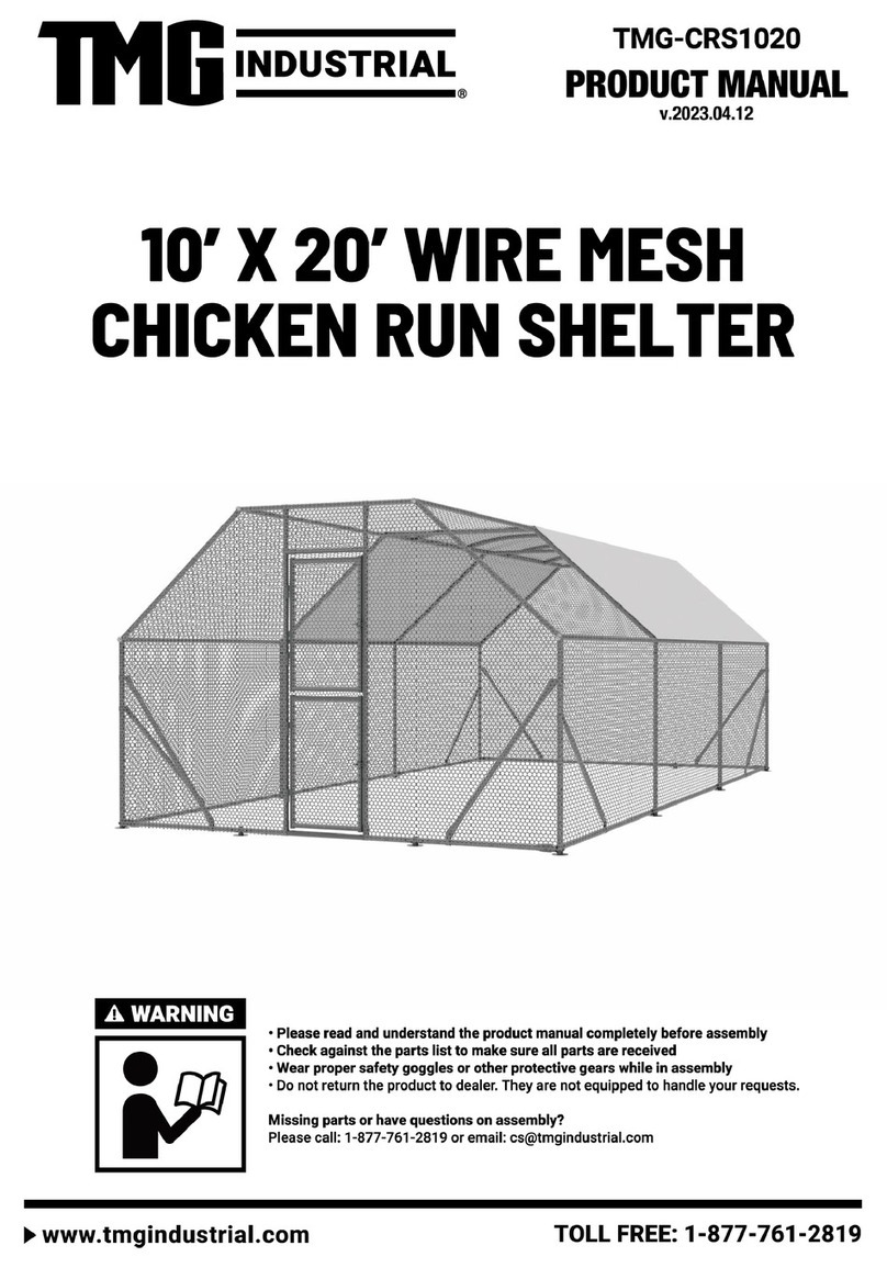
TMG TMG-ST3041CE User manual

TMG

TMG TMG-ST3041CE User manual

TMG TMG-CP2000-RD110 User manual

TMG

TMG TMG-CP2000-RD110 User manual

TMG TMG-LCP16 User manual

TMG

TMG TMG-LCP16 User manual

TMG TMG-ST3040C User manual

TMG

TMG TMG-ST3040C User manual

TMG TMG-ST2020L User manual

TMG

TMG TMG-ST2020L User manual

TMG PRO Series User manual

TMG

TMG PRO Series User manual
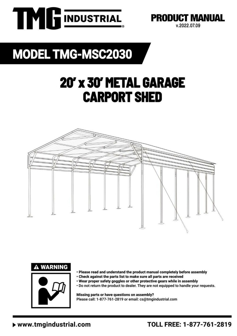
TMG TMG-DT3041-PRO User manual

TMG

TMG TMG-DT3041-PRO User manual

TMG TMG-MSC1220F User manual

TMG

TMG TMG-MSC1220F User manual

TMG TMG-ST3070-2.0 User manual

TMG

TMG TMG-ST3070-2.0 User manual

TMG TMG-ST3080E-1.0 User manual

TMG

TMG TMG-ST3080E-1.0 User manual

TMG TMG-184517ST User manual

TMG

TMG TMG-184517ST User manual

TMG TMG-ST2041V User manual

TMG

TMG TMG-ST2041V User manual

TMG TMG-MSC2020 User manual

TMG

TMG TMG-MSC2020 User manual

TMG TMG-DT3081 User manual

TMG

TMG TMG-DT3081 User manual

TMG TMG-DT3061 User manual

TMG

TMG TMG-DT3061 User manual

TMG ST3080V-1.0 User manual

TMG

TMG ST3080V-1.0 User manual

TMG ST2030 User manual

TMG

TMG ST2030 User manual

TMG TMG-MSC2030 User manual

TMG

TMG TMG-MSC2030 User manual

TMG TMG-DT3081-PRO User manual

TMG

TMG TMG-DT3081-PRO User manual

TMG TMG-MSC2020F User manual

TMG

TMG TMG-MSC2020F User manual

TMG TMG-DT3380 User manual

TMG

TMG TMG-DT3380 User manual

TMG TMG-DT4041CF User manual

TMG

TMG TMG-DT4041CF User manual

Popular Shelter manuals by other brands

Dancover ST03810 manual

Dancover

Dancover ST03810 manual

Kiwi Camping Savanna 3.5 Deluxe Pitching instructions

Kiwi Camping

Kiwi Camping Savanna 3.5 Deluxe Pitching instructions

Inkema RH14 instruction manual

Inkema

Inkema RH14 instruction manual

Harnois PLUS 16 manual

Harnois

Harnois PLUS 16 manual

HAYMAC eCONO Apex Fitting instructions

HAYMAC

HAYMAC eCONO Apex Fitting instructions

Sojag 500-6159684 Assembly manual

Sojag

Sojag 500-6159684 Assembly manual

Shelters4Less SR1583 Assembly instructions

Shelters4Less

Shelters4Less SR1583 Assembly instructions

Harnois CLASSIC quick start guide

Harnois

Harnois CLASSIC quick start guide

cantaport PJF Series manual

cantaport

cantaport PJF Series manual

No Butts Bin SR1585-F Assembly instructions
No Butts Bin

No Butts Bin SR1585-F Assembly instructions
Dunster House Artemis P3-3050PRG installation manual

Dunster House

Dunster House Artemis P3-3050PRG installation manual

Shelters4Less SR1557 Series Assembly instructions

Shelters4Less

Shelters4Less SR1557 Series Assembly instructions

AMERICANA OUTDOORS COLONIAL Assembly instructions
AMERICANA OUTDOORS

AMERICANA OUTDOORS COLONIAL Assembly instructions

X-METAL 37914 Assembly instructions

X-METAL

X-METAL 37914 Assembly instructions

No Butts Bin SR1551 Assembly instructions

No Butts Bin

No Butts Bin SR1551 Assembly instructions

Shelters4Less SR4500-01-16012017-S4L Assembly instructions

Shelters4Less

Shelters4Less SR4500-01-16012017-S4L Assembly instructions

Sealey GSS3030/G.V3 quick start guide

Sealey

Sealey GSS3030/G.V3 quick start guide

In the Garage Ultimate Car Shield instructions

In the Garage

In the Garage Ultimate Car Shield instructions

manuals.online logo
manuals.online logoBrands
  • About & Mission
  • Contact us
  • Privacy Policy
  • Terms and Conditions

Copyright 2025 Manuals.Online. All Rights Reserved.