manuals.online logo
Brands
  1. Home
  2. •
  3. Brands
  4. •
  5. TMG
  6. •
  7. Shelter
  8. •
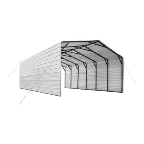
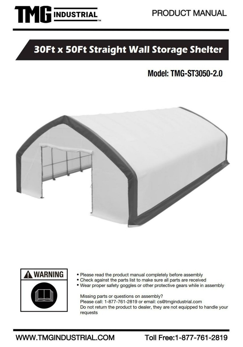
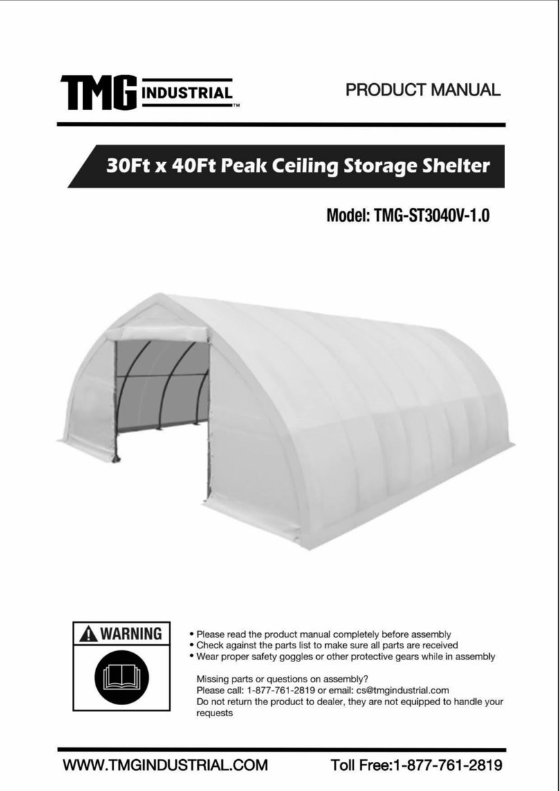
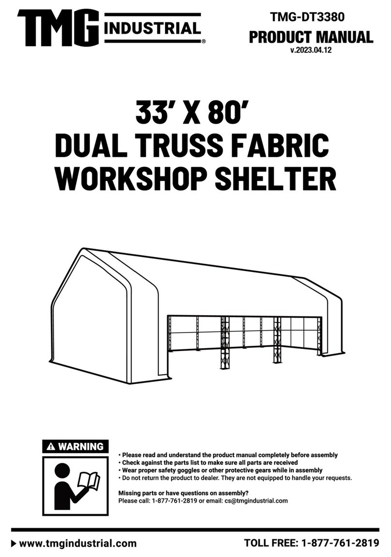
  9. TMG PRO Series User manual

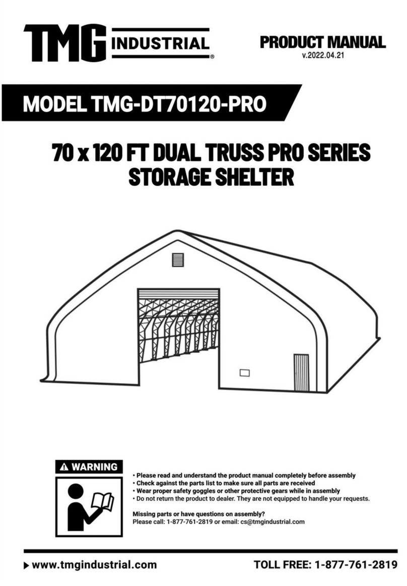
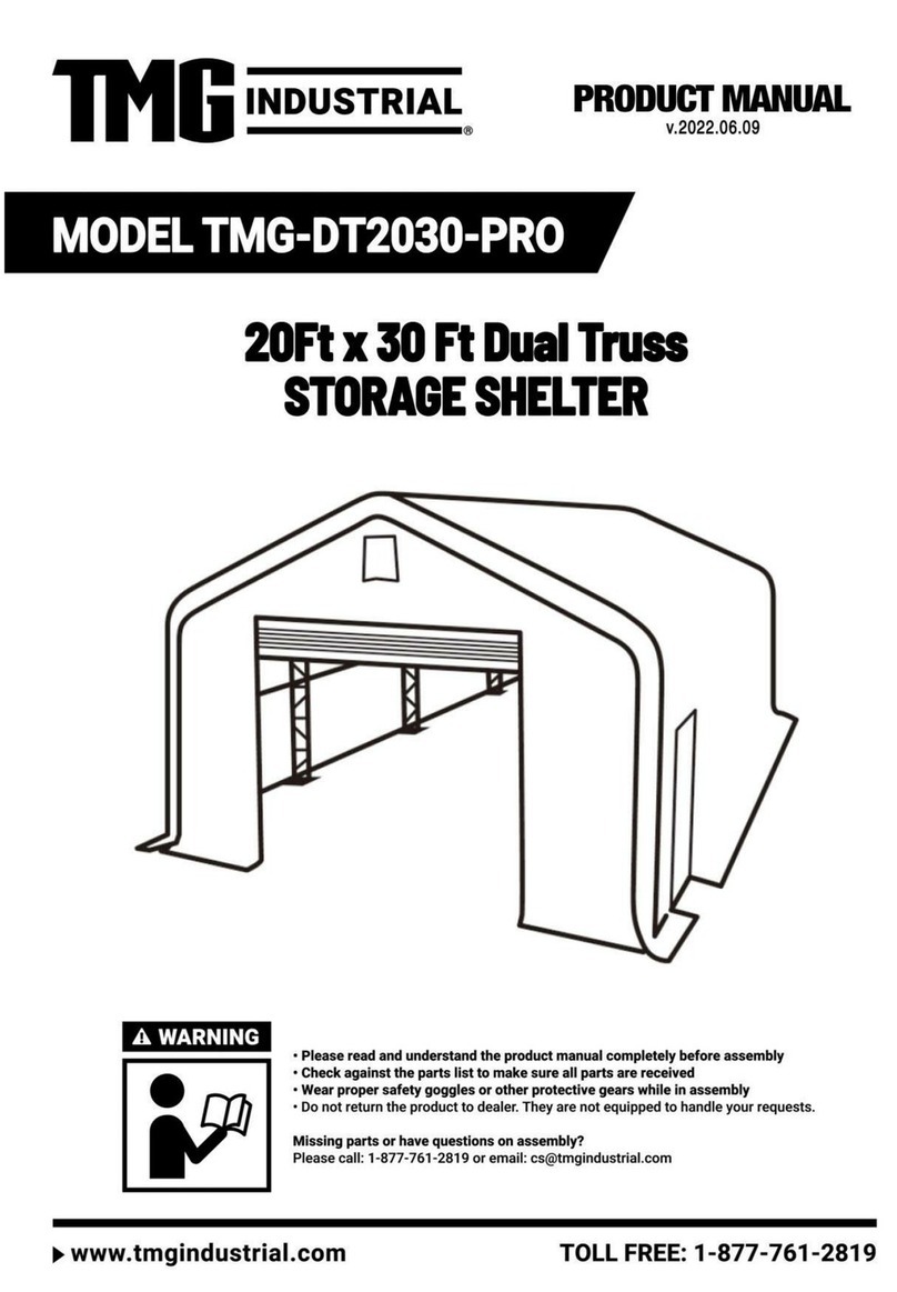
TMG PRO Series User manual

▶W W W . T M G I N D U S T R I A L . C O M P 0/ 30 T o l l F r e e : 1 - 877- 7 6 1 - 2 8 1 9
▶W W W . T M G I N D U S T R I A L . C O M P 1 / 30 T o l l F r e e : 1 - 877- 7 6 1 - 2 8 1 9
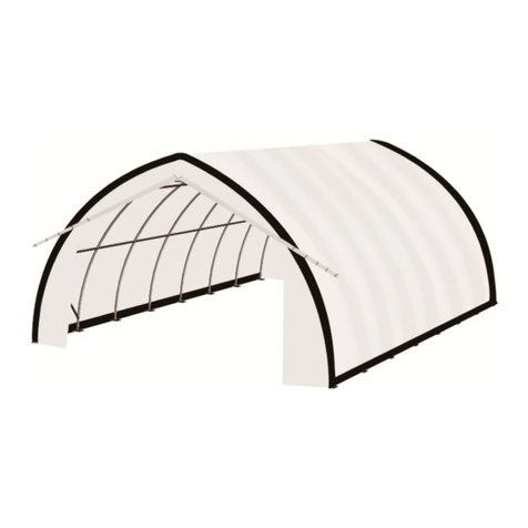
Main Specifications :
Assembly size : W6 x L19.2 x H4.5 (m) / 19.7 x 63 x 14.8 (ft)
Ridge height : 4.5m / 14.8 ft
Front and back door : 3.6 x 2.9 (m) / 11.8 x 9.5 (ft)
Shoulder height : 3 m / 9.9ft
Prior to assembly
Please go through the whole instruction manual completely. It is very important to follow
your local safety regulations and industry standards during installation. Regulations may
include but are not limited to :
-
Safety helmets, protective eyewear, and clothing
-
Safety harnesses for all elevated workers
-
Proper ladder, cage, and safety operation
Check all components and parts before installation. All parts are marked with a part
number, please refer to the parts list to ensure you have all parts.
Choose a day with low or no wind to install, it is hard to assemble with heavy wind. Do
not make any alterations to the structure. Do not hang any weight on the frame during
installation, including parts. We are not responsible for any damages or injuries caused
by inappropriate installation, unauthorized modifications or extreme weather.
This building is not intended for human occupancy.
It is recommended to use heavy duty duct tapes to tape the tube connection joint spots to
protect the cover from damage and worn. It will help to extend the cover life span.
Check the parts list below to make sure all parts are received prior to assembly.
▶W W W . T M G I N D U S T R I A L . C O M P 2 / 30 T o l l F r e e : 1 - 877- 7 6 1 - 2 8 1 9
Frame structure diagram.
▶W W W . T M G I N D U S T R I A L . C O M P 3 / 30 T o l l F r e e : 1 - 877- 7 6 1 - 2 8 1 9
TMG-DT2064-PRO Part List
Parts
Code
Graphical
Description
Length
Qty
Box
1
Peak arch tube
(for middle trusses )
L2020mm
7
B
1A
Peak arch tube
(for front and rear truss)
L2020mm
2
B
2
Upper rafter tube
(for middle trusses)
L1495mm
14
B
2A
Upper rafter tube
(for front and rear truss)
L1495mm
4
B
3
Shoulder tube
(for middle trusses)
L1707mm
14
A
3A
Shoulder tube
(front and rear trusses)
L1707mm
4
A
4
Sidewall tube
(middle trusses)
L2163mm
13
A
4A
Sidewall tube(front and
rear left truss)
L2163mm
2
A
4B
Sidewall tube
(rear right truss)
L2163mm
1
A
4C
Sidewall tube
(front right truss)
L2163mm
1
A
4D
Sidewall tube
(second right truss)
L2163mm
1
A
5
Roof purlin
(horizontal tube)
L2440mm
55
A
5L
Baseplate for front and
rear truss left corners
L320xW260mm
2
B
5R
Baseplate for front and
rear truss right corners
L320xW260mm
2
B
▶W W W . T M G I N D U S T R I A L . C O M P 4 / 30 T o l l F r e e : 1 - 877- 7 6 1 - 2 8 1 9
6L
Left baseplate of front
door frame
L200xW150mm
2
B
6R
Right baseplate of front
door frame
L200xW150mm
2
B
7
Baseplates for middle
truss
L280xW260mm
14
B
7A
Ratchets
L155mm
43
B
7B
Expansion bolts
φ16x150mm
84
B
8
Ceiling cross bar
(front and rear truss)
L1748mm
2
B
9
Ceiling cross bar
(front and rear truss)
L1898mm
2
B
9L
Front and rear vertical
door rail
(left side upper part)
L1465mm
2
B
9R
Front and rear vertical
door rail
(right side upper part)
L1465mm
2
B
9A
Side door left tube
L2027mm
1
B
9B
Side door right tube
L2027mm
1
B
9C
Side door
L2005xW925mm
1
B
10
Door center vertical
supporting rod for cross
beam
L930mm
2
B
10L
Front and rear vertical
door rail
(left side lower part)
L2015mm
2
B
10R
Front and rear vertical
door rail
(right side lower part)
L2015mm
2
B
11
Door frame horizontal
tube
(front and rear truss)
L940mm
4
B
▶W W W . T M G I N D U S T R I A L . C O M P 5 / 30 T o l l F r e e : 1 - 877- 7 6 1 - 2 8 1 9
11C
Side door upper tube
L2328mm
1
A
12
Bottom tension bar
(front and rear truss)
L930mm
4
B
13
Door hand winch
crossing tube
L944mm
2
B
14
Top cover tension tube
(for both bottom sides)
L1993mm
17
B
14A
Top cover tension tube
(for both bottom sides)
L1900mm
2
B
14B
Top cover tension tube
L2450mm
1
A
15
Roll up door dropping
tubes (to connect #16)
L1856mm
10
B
16
Roll up door dropping
tubes (to connect #15)
L1859mm
10
B
17
Sidewall frame steel
tension cables
φ6x3700mm
18
B
18
Ridge steel tension cables
(front and rear trusses)
φ6x2800mm
16
B
19
Middle truss crossing
steel tension cables
φ6x2m
7
B
20
Front and rear truss left
and right steel cables
φ6x3m
4
B
21
Tie down straps
(for #7A)
W38xL800mm
43
B
22
Cable connection plate
91mm
26
B
22A
Pressing plate
L2m
6
B
22B
Pressing plate
L1m
5
B
23
Roll up door hand winch
(3T)
2
B
23A
Wire rope for front and
rear door hand winch
L10m
2
B
▶W W W . T M G I N D U S T R I A L . C O M P 6 / 30 T o l l F r e e : 1 - 877- 7 6 1 - 2 8 1 9
23B
Right pulley system for
front and rear doors
L150mm
2
B
23C
Left pulley system for
front and rear doors
L150mm
2
B
23D
Clip
6
B
24
Front and rear vertical
door rail connection plate
L240mm
4
B
24A
Front and rear vertical
door rail end plate
(floatable to keep door
rail straight)
L220mm
4
B
25
Tension tube end water
plug
φ32
14
B
26
Tube clamps
φ48
6
B
27
Plastic hose (in grooves
at both ends of #33)
φ25xL4m
7
B
27A
Connector
(for connection #27)
φ25
6
B
28
Self locking bolt and nuts
M10x70mm
62
B
29
Strengthened bolt and
nuts
M12x30mm
234
B
30
Hex bolt and nuts
M10x50mm
10
B
31
Hex bolt and nuts
M10x70mm
50
B
32
Braided rope
(tie to front and back
doors)
L100m
1
B
33
Roof fabric tarp cover
L13.3xW19.8m
1
B
34
Front and rear truss cover
panel
L6xW4.7m
2
B
▶W W W . T M G I N D U S T R I A L . C O M P 7 / 30 T o l l F r e e : 1 - 877- 7 6 1 - 2 8 1 9
35
Front and rear roll up
door cover panel
L3.55xW3.46m
2
B
36
Front and rear fabric tarp
secure pin
200mm
2
B
37
Tapping screw
#12x25mm
76
B
38
Scratch resistant tape
10m
3
B
▶W W W . T M G I N D U S T R I A L . C O M P 8 / 30 T o l l F r e e : 1 - 877- 7 6 1 - 2 8 1 9
Step 1 : Base plate positioning and installation.

Installation diagram of expansion bolt.
No.
Part
Qty
No.
Part
Qty
5L
2
6R
2
5R
2
7
14
6L
2
7B
80
▶W W W . T M G I N D U S T R I A L . C O M P 9 / 30 T o l l F r e e : 1 - 877- 7 6 1 - 2 8 1 9
Step 2 :Assemble all trusses.
Front truss.
No.
Part
Qty
No.
Part
Qty
1A
1
4A
1
2A
2
4C
1
3A
2
29
18
▶W W W . T M G I ND U S T R I A L .C O M P 10/30 T o l l F r e e : 1 - 877-761- 2 8 1 9
Second truss.
No.
Part
Qty
No.
Part
Qty
1
1
4
1
2
2
4D
1
3
2
29
18
▶W W W . T M G I ND U S T R I A L .C O M P 11/30 T o l l F r e e : 1 - 877-761- 2 8 1 9
Rear truss.
No.
Part
Qty
No.
Part
Qty
1A
1
4A
1
2A
2
4B
1
3A
2
29
18
▶W W W . T M G I ND U S T R I A L .C O M P 12/30 T o l l F r e e : 1 - 877-761- 2 8 1 9
The rest of the trusses. (2 trusses)
No.
Part
Qty
No.
Part
Qty
1
1x6
4
2x6
2
2x6
29
18x6
3
2x6
▶W W W . T M G I ND U S T R I A L .C O M P 13/30 T o l l F r e e : 1 - 877-761- 2 8 1 9
Lay down all (5) trusses on the ground when the assembly is all completed and
before moving to next step, and then wrap (#38) around the sharp points of the
joint to avoid friction between the fabric and the interface, resulting in fabric
damage.
No.
Part
Qty
38
3
▶W W W . T M G I ND U S T R I A L .C O M P 14/30 T o l l F r e e : 1 - 877-761- 2 8 1 9
Step 3 : Put up the front truss. (It is suggested to use crane for hoisting)
No.
Part
Qty
29
8
▶W W W . T M G I ND U S T R I A L .C O M P 15/30 T o l l F r e e : 1 - 877-761- 2 8 1 9
Step 4 : Put up the rest trusses.
Refer to step 3 to put up the rest trusses, connect all purlins (#5) with bolt
(#28) and secure all bolts firmly on each span before going to next truss .
No.
Part
Qty
No.
Part
Qty
5
6
29
8
28
12
▶W W W . T M G I ND U S T R I A L .C O M P 16/30 T o l l F r e e : 1 - 877-761- 2 8 1 9
Repeat above step to put up all other trusses (from 3rd to 5th truss), and
connect all purlins.
No.
Part
Qty
No.
Part
Qty
5
49
29
56
28
50
▶W W W . T M G I ND U S T R I A L .C O M P 17/30 T o l l F r e e : 1 - 877-761- 2 8 1 9
Install the side door frame.
No.
Part
Qty
No.
Part
Qty
7B
4
11C
1
9A
1
31
6
9B
1
▶W W W . T M G I ND U S T R I A L .C O M P 18/30 T o l l F r e e : 1 - 877-761- 2 8 1 9
Install the side door.
No.
Part
Qty
9C
1
37
8
Align the lock cylinder
boss with the hole.
▶W W W . T M G I ND U S T R I A L .C O M P 19/30 T o l l F r e e : 1 - 877-761- 2 8 1 9
Tension cable installation . All cables are diagonally installed on each side of the
interval.
No.
Part
Qty
No.
Part
Qty
17
18
19
7
18
16
22
26

Other manuals for PRO Series

7

This manual suits for next models

1

Other TMG Shelter manuals

TMG DUAL TRUSS PRO Series User manual

TMG

TMG DUAL TRUSS PRO Series User manual

TMG TMG-LCP16 User manual

TMG

TMG TMG-LCP16 User manual

TMG PRO Series User manual

TMG

TMG PRO Series User manual
TMG TMG-ST4081V User manual

TMG

TMG TMG-ST4081V User manual

TMG TMG-ST3070-2.0 User manual

TMG

TMG TMG-ST3070-2.0 User manual

TMG TMG-ST4061E User manual

TMG

TMG TMG-ST4061E User manual

TMG ST3080V-1.0 User manual

TMG

TMG ST3080V-1.0 User manual

TMG 3040 User manual

TMG

TMG 3040 User manual

TMG TMG-MSC2020 User manual

TMG

TMG TMG-MSC2020 User manual
TMG TMG-DT3380 User manual

TMG

TMG TMG-DT3380 User manual

TMG TMG-DT3041 User manual

TMG

TMG TMG-DT3041 User manual

TMG TMG-CP2000-RD110 User manual

TMG

TMG TMG-CP2000-RD110 User manual

TMG TMG-DT3081-PRO User manual

TMG

TMG TMG-DT3081-PRO User manual

TMG TMG-184517ST User manual

TMG

TMG TMG-184517ST User manual

TMG TMG-ST4061E User manual

TMG

TMG TMG-ST4061E User manual
TMG TMG-MSC2030F User manual

TMG

TMG TMG-MSC2030F User manual

TMG ST2030 User manual

TMG

TMG ST2030 User manual

TMG TMG-ST3060V-1.0 User manual

TMG

TMG TMG-ST3060V-1.0 User manual

TMG TMG-ST3050-2.0 User manual

TMG

TMG TMG-ST3050-2.0 User manual

TMG TMG-1220RST User manual

TMG

TMG TMG-1220RST User manual

TMG TMG-CRS1020 User manual

TMG

TMG TMG-CRS1020 User manual

TMG TMG-ST2041V User manual

TMG

TMG TMG-ST2041V User manual

TMG TMG-DT3041-PRO User manual

TMG

TMG TMG-DT3041-PRO User manual

TMG TMG-DT3063-PRO User manual

TMG

TMG TMG-DT3063-PRO User manual

Popular Shelter manuals by other brands

Vikre Handel AS JIT-250A Assembly manual

Vikre Handel AS

Vikre Handel AS JIT-250A Assembly manual

Inkema RH14 instruction manual

Inkema

Inkema RH14 instruction manual

Sojag 500-9162387 Assembly manual

Sojag

Sojag 500-9162387 Assembly manual

FSI DAT Series instruction manual

FSI

FSI DAT Series instruction manual

Sojag 500-6159233 Assembly instructions

Sojag

Sojag 500-6159233 Assembly instructions

ShelterLogic ShelterCoat 12'W x 8'H Peak manual

ShelterLogic

ShelterLogic ShelterCoat 12'W x 8'H Peak manual

SURF & TURF CANOPRO LITE SHELTER 5ft x 5ft Assembly guide

SURF & TURF

SURF & TURF CANOPRO LITE SHELTER 5ft x 5ft Assembly guide

No Butts Bin SR1584-F Assembly instructions

No Butts Bin

No Butts Bin SR1584-F Assembly instructions

Hardlife Utility C2020 instruction manual

Hardlife Utility

Hardlife Utility C2020 instruction manual

Storage Canopy C2620R Assembly instructions

Storage Canopy

Storage Canopy C2620R Assembly instructions

Vikre Handel AS SS305018 Assembly instructions

Vikre Handel AS

Vikre Handel AS SS305018 Assembly instructions

Duratuf KIWI SHEDS MK3 Assembly instructions

Duratuf KIWI

Duratuf KIWI SHEDS MK3 Assembly instructions

Hardlife Utility C4040 Assembly manual

Hardlife Utility

Hardlife Utility C4040 Assembly manual

Shappell DX4000 manual

Shappell

Shappell DX4000 manual

Sealey Power Products GSS150819SD instructions

Sealey

Sealey Power Products GSS150819SD instructions

Inkema ABRE instruction manual

Inkema

Inkema ABRE instruction manual

AGF COLLECTanDRAIN 5680A installation instructions

AGF

AGF COLLECTanDRAIN 5680A installation instructions

Storage Canopy 40x60x15 ST Container shelter Assembly manual

Storage Canopy

Storage Canopy 40x60x15 ST Container shelter Assembly manual

manuals.online logo
manuals.online logoBrands
  • About & Mission
  • Contact us
  • Privacy Policy
  • Terms and Conditions

Copyright 2025 Manuals.Online. All Rights Reserved.