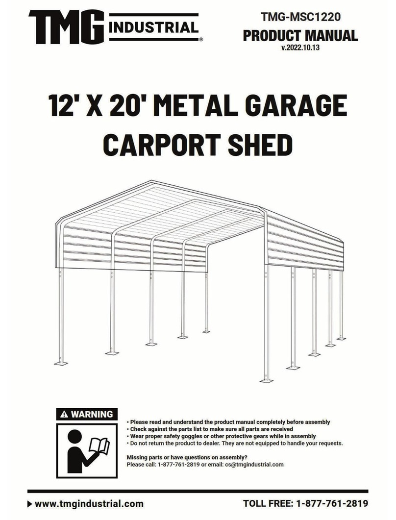
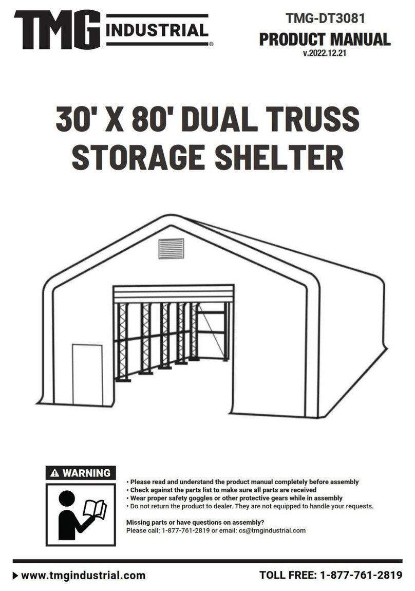
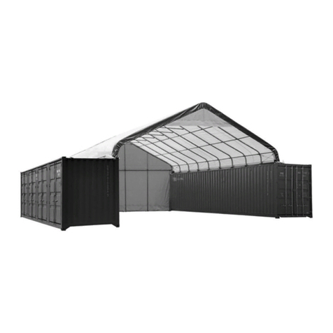
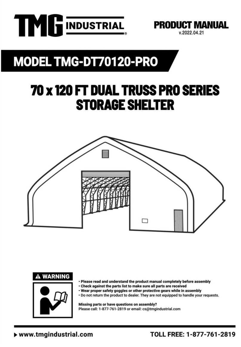
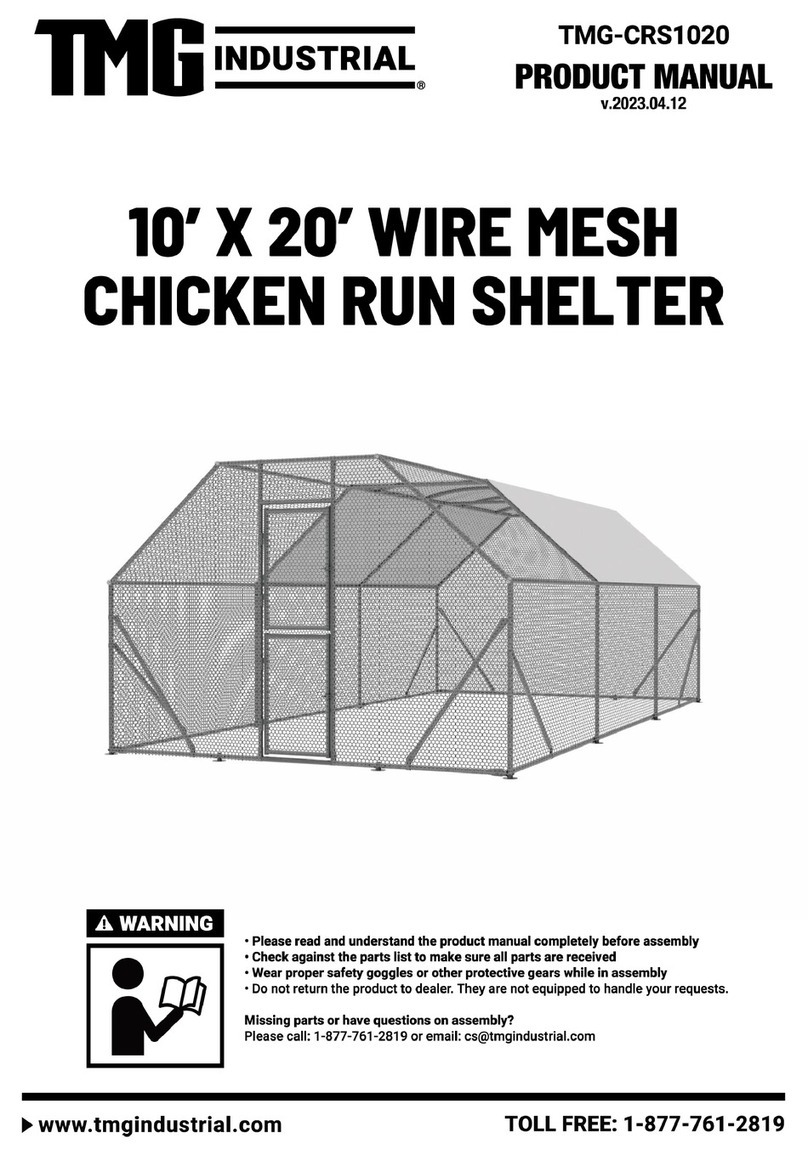
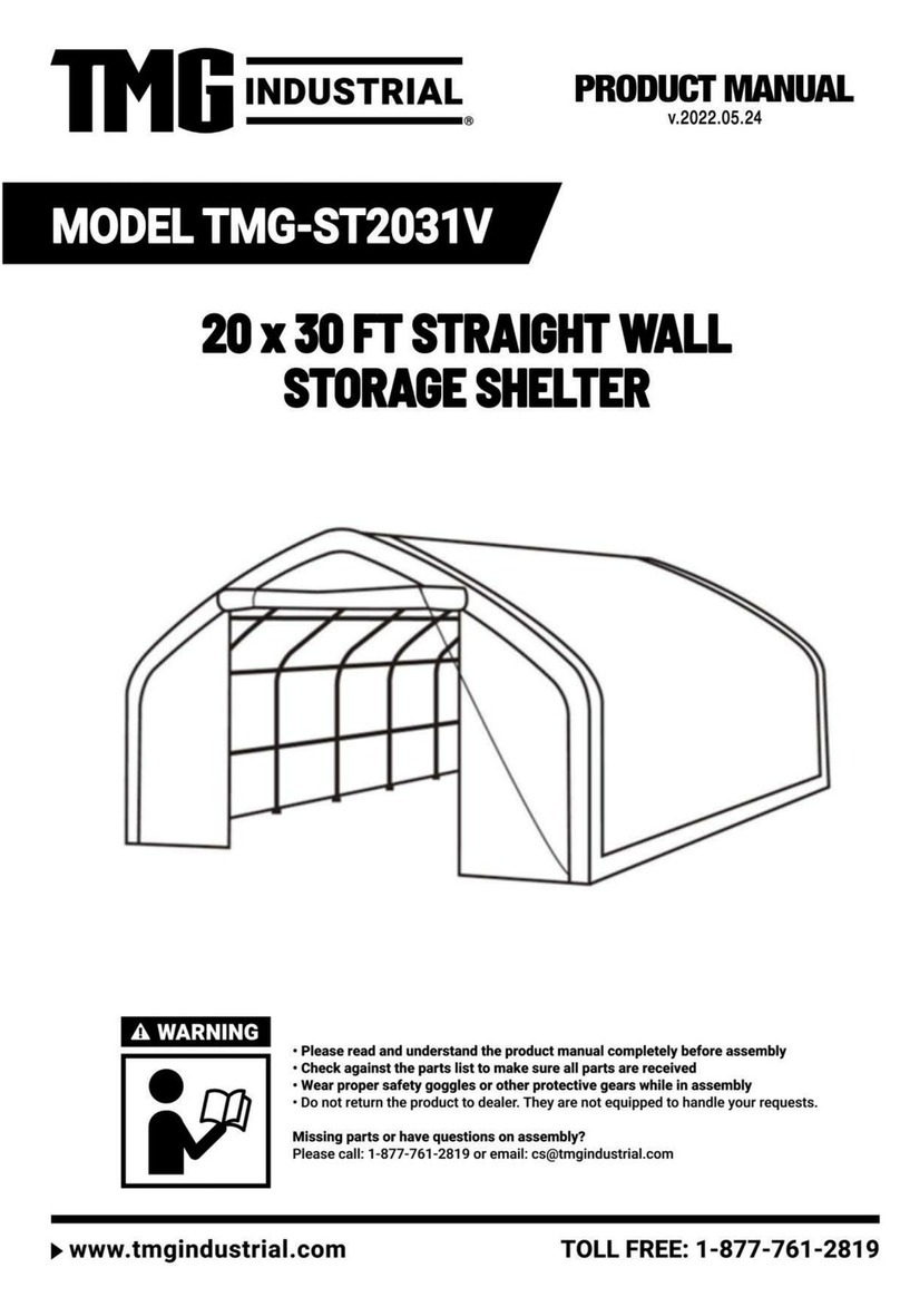
TMG PRO Series User manual

▶W W W . T M G I N D U ST R I A L . C O M P 0 / 4 0 T o l l F r e e : 1 - 8 7 7 - 761-2819

▶W W W . T M G I N D U ST R I A L . C O M P 1 / 4 0 T o l l F r e e : 1 - 8 7 7 - 761-2819
Main Specifications:
Assembly size : W21.3 x L30 x H8.5 (m) / 70ft x 100ft x 28ft
Outside width : 21.3 m / 70ft, inside width : 20.3 m / 67ft, length : 30 m /
99 ft
Ridge peak height : 8.5 m /28 ft
Peak clearance height : 8m / 26 ft
Roll up door : 5.5 x 4.88 (m)/ 18 ft x 16 ft
Shoulder wall clearance height : 3.6 m / 12 ft
Prior to assembly
Please go through the whole instruction manual completely. It is very
important to follow your local safety regulations and industry standards during
installation. Regulations may include but are not limited to:
-
Safety helmets, protective eyewear, and clothing
-
Safety harnesses for all elevated workers
-
Proper ladder, cage, and safety operation
Check all components and parts before installation. All parts are marked with a part
number, please refer to the parts list to ensure you have all parts.
Choose a day with low or no wind to install, it is hard to assemble with heavy
wind. Do not make any alterations to the structure. Do not hang any weight on
the frame during installation, including parts. We are not responsible for any
damages or injuries caused by inappropriate installation, unauthorized
modifications or extreme weather.
This building is not intended for human occupancy.
It is recommended to use heavy duty duct tapes to tape the tube connection
joint spots to protect the cover from damage and worn. It will help to extend the
cover life span.
Check the parts list below to make sure all parts are received prior to assembly.

▶W W W . T M G I N D U ST R I A L . C O M P 2 / 4 0 T o l l F r e e : 1 - 8 7 7 - 761-2819
Frame structure diagram.

▶W W W . T M G I N D U ST R I A L . C O M P 3 / 4 0 T o l l F r e e : 1 - 8 7 7 - 761-2819
TMG-DT70100-PRO Part List
Parts
Code
Graphical
Description
Length
Qty
BOX
1
Peak arch tube
(for middle trusses)
L3193mm
14
A
1A
Peak arch tube
(for front and rear
trusses)
L3193mm
2
A
2
Upper and down rafter
tube(for middle
trusses)
L3104mm
56
Cx20
Dx20
Ex16
2A
Upper rafter tube
(for front and rear
trusses)
L3104mm
4
F
2B
Middle rafter tube
(for front and rear
trusses)
L3104mm
4
F
2C
Down rafter tube
(for front and rear
trusses)
L3104mm
4
E
2D
Middle rafter tube
(for middle trusses)
L3104mm
28
Bx20
Fx8
3
Shoulder tube
(for middle trusses)
L2094mm
28
Ix13
Jx15
3A
Shoulder tube
(front and rear trusses)
L2094mm
4
Ix4
4
Sidewall tube
(middle trusses)
L2514mm
28
Gx28
4A
Sidewall tube
(for front and rear
trusses)
L2514mm
4
Hx4
5
Roof purlin
(horizontal tube)
L2040mm
225
H

▶W W W . T M G I N D U ST R I A L . C O M P 4 / 4 0 T o l l F r e e : 1 - 8 7 7 - 761-2819
5A
Diagonal bracing tube
L2540mm
24
C
5B
Support tube
L2820mm
2
B
5C
Support tube
L2820mm
4
B
5L
Baseplate for front and
rear truss left corners
W280xL480mm
2
A
5R
Baseplate for front and
rear truss right corners
W280xL480mm
2
A
6
Baseplates
W280xL430mm
26
A
6L
Left column baseplate
W200xL410mm
2
A
6R
Right column
baseplate
W200xL410mm
2
A
6A
Baseplates
W280xL430mm
2
A
7
Ratchets
3T
132
A
7B
Clip
6
A
7L
Left baseplate of door
frame
W200xL410mm
2
A
7R
Right baseplate of
door frame
W200xL410mm
2
A
8
Top cover tension tube
(for both bottom sides)
L1993mm
30
D
8A
Top cover tension tube
(for both bottom sides)
L650mm
2
D

▶W W W . T M G I N D U ST R I A L . C O M P 5 / 4 0 T o l l F r e e : 1 - 8 7 7 - 761-2819
8B
Top cover tension tube
(for both bottom sides)
L570mm
2
D
8L
Front and rear vertical
door rail
(left side upper part)
L1300mm
2
D
8R
Front and rear vertical
door rail
(right side upper part)
L1300mm
2
D
9
Column baseplate
W200xL410mm
4
A
9L
Front and rear vertical
door rail
(left side middle part)
L2800mm
2
D
9R
Front and rear vertical
door rail
(right side middle part)
L2800mm
2
D
10L
Front and rear vertical
door rail
(left side lower part)
L2795mm
2
D
10R
Front and rear vertical
door rail
(right side lower part)
L2795mm
2
D
11
Lower vertical tubes
L2880mm
6
E
11A
Upper vertical tubes
L1563mm
4
H
11B
Upper vertical tubes
L3008mm
4
B
11C
Lower vertical tubes
L2880mm
2
B
12
Door cross tubes
(left and right)
L2723mm
4
B
12A
Door cross tubes
(left and right)
L2244mm
8
H
12B
Door cross tubes
(left)
L2325mm
2
H
12C
Door cross tubes
(right)
L2325mm
2
B
13
Door cross beam (left)
L2684mm
2
B

▶W W W . T M G I N D U ST R I A L . C O M P 6 / 4 0 T o l l F r e e : 1 - 8 7 7 - 761-2819
13A
Door cross beam (right)
L2854mm
2
B
13B
Door center vertical
supporting rod for
cross beam
L2564mm
2
B
13C
Upper cross tubes
(left and right)
L2702mm
8
B
14
Door hand winch
crossing tube
L2244mm
2
B
14A
Side door left tube
L2200mm
2
H
14B
Side door right tube
L2200mm
2
H
14C
Side door upper tube
L920mm
2
H
14D
Side door
W925xL2005mm
2
J
15
Bottom tension bar
(front and rear truss)
L2460mm
2
E
15A
Bottom tension bar
(front and rear truss)
L2650mm
4
E
15B
Bottom tension bar
(front and rear truss)
L2200mm
4
E
15C
Bottom tension bar
(front and rear truss)
L820mm
2
E
15D
Bottom tension bar
(front and rear truss)
L590mm
2
E
16
Roll up door dropping
tubes (to connect
#16A)
L2810mm
16
D
16A
Roll up door dropping
tubes (to connect #16)
L2775mm
16
D
17
Front and rear truss left
and right steel cables
L5700mm
4
A
18
Sidewall frame steel
tension cables
L4000mm
34
A
19
Middle truss crossing
steel tension cables
L8460mm
14
A
20
Expansion bolts
φ16x150mm
184
A

▶W W W . T M G I N D U ST R I A L . C O M P 7 / 4 0 T o l l F r e e : 1 - 8 7 7 - 761-2819
21
Tie down straps
(for #7)
W38xL1000mm
130
A
22
Cable connection plate
L91mm
20
A
23
Roll up door hand
winch
3T
2
A
23A
Wire rope for front and
rear door hand winch
L25m
2
A
24
Front and rear vertical
door rail connection
plate
L240mm
16
A
24A
Front and rear vertical
door rail end plate
(floatable to keep door
rail straight)
L215mm
12
A
24B
Tube clamps
φ76mm
28
A
24D
Tube clamps
φ58mm
12
A
25
Tension tube end
water plug
φ32mm
36
A
26
Self locking bolt and
nuts
M10x100
240
A
27
Self locking bolt and
nuts
M8x80
36
A
28
Strengthened bolt and
nuts
M14x30
768
A
29
Hex bolt and nuts
M10x100
154
A
29A
Hex bolt and nuts
M10x70
12
A
30
Hex bolt and nuts
M10x30
22
A
30A
Hex bolt and nuts
M12x30
16
A
30B
Hex bolt and nuts
M10x50
40
A

▶W W W . T M G I N D U ST R I A L . C O M P 8 / 4 0 T o l l F r e e : 1 - 8 7 7 - 761-2819
31
Braided rope
L180m
2
A
32
Top cover A
W14.3xL31.2m
1
F
33
Top cover B
W17xL31.2m
1
F
34
Front and rear truss
cover panel
W8.9xL21.3m
2
H
34A
Front and rear roll up
door cover panel
W5.4xL5.5m
2
H
35
Front and rear fabric
tarp secure pin
L150mm
4
A
36
Plastic hose
φ25mmxL4m
32
C
36A
Connector
(for connection #36)
φ25mm
28
A
37
Scratch resistant tape
L10m
8
A
38
Pressing plate
L2000mm
12
D
38A
Pressing plate
L1000mm
6
D
39
Tapping screw
#12x25mm
136
A

▶W W W . T M G I N D U ST R I A L . C O M P 9 / 4 0 T o l l F r e e : 1 - 8 7 7 - 761-2819
Step 1 : Baseplate positioning and installation.
Installation diagram of expansion bolt.
NO.
PART
Qty
NO.
PART
Qty
5L
2
6R
2
5R
2
7L
2
6
26
7R
2
6A
2
9
4
6L
2
20
176

▶W W W .T M G IN D U ST R I AL . CO M P 12/ 4 0 T o l l Fr e e : 1 - 877- 7 6 1 - 2 8 19
Step 4 : wrap (#37) around the sharp points of the joint to avoid friction between the
fabric and the interface.
NO.
PART
Qty
37
8

▶W W W .T M G IN D U ST R I AL . CO M P 13/ 4 0 T o l l Fr e e : 1 - 877- 7 6 1 - 2 8 19
Step 5 : Put up the front truss (It is suggested to use crane for hoisting).
NO.
PART
Qty
28
8

▶W W W .T M G IN D U ST R I AL . CO M P 14/ 4 0 T o l l Fr e e : 1 - 877- 7 6 1 - 2 8 19
Step 6 : Put up the 2nd truss, and connect all purlins (#5) between 1st and 2nd.
NO.
PART
Qty
5
15
26
30
28
8

▶W W W .T M G IN D U ST R I AL . CO M P 15/ 4 0 T o l l Fr e e : 1 - 877- 7 6 1 - 2 8 19
Step 7 : Repeat above step to put up all other trusses, and connect all purlins.
NO.
PART
Qty
5
210
26
210
28
112

▶W W W .T M G IN D U ST R I AL . CO M P 16/ 4 0 T o l l Fr e e : 1 - 877- 7 6 1 - 2 8 19
Step 8 :
Installation of diagonal Purlins (The front and rear mounting methods are the
same).
NO.
PART
Qty
5A
24
24B
28
30B
28

▶W W W .T M G IN D U ST R I AL . CO M P 17/ 4 0 T o l l Fr e e : 1 - 877- 7 6 1 - 2 8 19
Step 9 : Tension cable installation,All cables are diagonally installed on each.
NO.
PART
Qty
18
34
19
14
22
20

▶W W W .T M G IN D U ST R I AL . CO M P 18/ 4 0 T o l l Fr e e : 1 - 877- 7 6 1 - 2 8 19
Step 10 : Door column installation (The front and rear mounting methods are the
same).
NO.
PART
Qty
NO.
PART
Qty
NO.
PART
Qty
8L
2
13
2
27
4
8R
2
13A
2
29
86
9L
2
13B
2
29A
8
9R
2
13C
4
30
6
10L
2
24
16
10R
2
24A
4

▶W W W .T M G IN D U ST R I AL . CO M P 19/ 4 0 T o l l Fr e e : 1 - 877- 7 6 1 - 2 8 19
Step 11-1 :
Door support pipe installation (The front and rear mounting methods are the same).
NO.
PART
Qty
NO.
PART
Qty
NO.
PART
Qty
11
4
13C
2
27
16
11A
2
15
2
29
28
11B
2
15A
2
30
6
12
2
15B
2
30A
8
12A
4
17
2
12B
2
24A
4
Other manuals for PRO Series
7
This manual suits for next models
1
Table of contents
Other TMG Shelter manuals

TMG
TMG PRO Series User manual

TMG
TMG TMG-MS2119 User manual

TMG
TMG 3040 User manual

TMG
TMG ST2030 User manual

TMG
TMG TMG-ST3070-2.0 User manual

TMG
TMG TMG-ST2040C-1.0 User manual

TMG
TMG TMG-ST3070V-2.0 User manual

TMG
TMG TMG-CP2030F-1.0 User manual

TMG
TMG TMG-CRS1040 User manual
TMG
TMG TMG-ST3060V-1.0 User manual

TMG
TMG TMG-ST4081E User manual

TMG
TMG TMG-184517ST User manual

TMG
TMG TMG-MSC1220 User manual

TMG
TMG TMG-ST3041CE User manual

TMG
TMG TMG-MSC2020 User manual
TMG
TMG TMG-ST4061E User manual

TMG
TMG TMG-DT3041 User manual

TMG
TMG TMG-MSC2020F User manual

TMG
TMG TMG-CRS1020 User manual

TMG
TMG TMG-ST4081V User manual