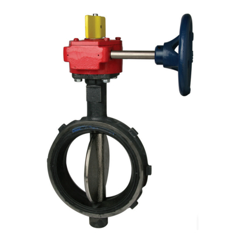
Tyco STAR Model A User manual

PreactionValve
Model A, 3 Inch (DN80)
With Double Interlock
Electric/Pneumatic Release Trim
GENERAL DESCRIPTION
The Star 3 inch (DN80) Model A Preaction Valve with
Double Interlock Electric/Pneumatic Release Trim is de-
signed for use in applications, such as refrigerated areas,
requiring the maximum degree of protection against inad-
vertent flooding of the sprinkler system piping.In order for
the Model A Preaction Valve to automatically actuate and
permit water to enter the sprinkler system piping, two in-
dependent events must occur — the electric fire detection
system must respond to a fire condition and one or more
automatic sprinklers must operate.
The Model A Preaction Valve features a double seat de-
sign eliminating the use of a separate air check valve in
the system riser. Also, the Model A Preaction Valve has
been designed to operate without prime water, conse-
quently eliminating yet another additional check valve in
the system riser for refrigerated area systems.
In the case of the electric/pneumatic release of the Model
A Preaction Valve, the releasing trim consisting of both a
Solenoid Valve (electrically operated releasing valve) and
a Dry Pilot Actuator (air operated releasing valve) in a se-
ries configuration is utilized. The double seat design of
the Model A Preaction Valve isolates the system air pres-
sure, which holds the Dry Pilot Actuator closed.The Sole-
noid Valve remains closed until it is electrically energized
by a releasing panel that is operated by either an electric
fire detection device or electric manual pull station.
As an option for water supplies of 35 psi (2.4 bar) or
more, the Model A Preaction Valve may be equipped with
414-570-5000 • 800-558-5236 • FAX 414-570-5010 6-00
2-4.1.10
STAR SPRINKLER INC.
www.starsprinkler.com
#3000 Valve, F x F
#3008 Trim
FIGURE 1
GENERAL ARRANGEMENT FOR ELECTRIC/PNEUMATIC DOUBLE INTERLOCK PREACTION SYSTEM
RELEASE TRIM
MODEL A PREACTION VALVE
WITH DOUBLE INTERLOCK
ELECTRIC/PNEUMATIC
WATER SUPPLY
OPEN)
SYSTEM MAIN
CONTROL VALVE
(SUPERVISED
MAINTENANCE DEVICE
(OR REFRIGERATED SPACE
AIR SUPPLY PER NFPA 13)
SUPPLY WATER
CIRCUIT
FIRE
DETECTION
INITIATING
OPEN)
S
Y
S
TEM
SHUT-OFF VALVE
(SUPERVISED
AUT
O
MATI
CS
PRINKLER
S
2FEET
(609.6 mm)
MINIMUM
SYSTEM TRIP
TEST FLOW VALVE
PRESSURE
SYSTEM AIR
PRESSURE
MODEL S460 AIR
AUDIBLE
ALARM
CIRCUIT
BACK-UP
PANEL
WITH 24 VDC
BATTERY
RELEASING
ELECTRIC DETECTION
WATERFLOW ALARM
INITIATING CIRCUIT
24 VDC SOLENOID VALVE
RELEASING CIRCUIT
-
SUPERVISORY ALARM
INITIATING CIRCUITS:
-
-
ELECTRIC
MANUAL PULL
INITIATING
SYSTEM SHUT-OFF VALVE
LOW AIR
SYSTEM MAIN CONTROL VALVE
CIRCUIT
120 VAC
OBSOLETE

STAR SPRINKLER INC.
Page 2 2-4.1.10
FIGURE 2
MODEL A PREACTION VALVE
3 INCH (DN80) ASSEMBLY
DIFFERENTIAL
ASSEMBLY
VALVE PLUNGER
29
38
39
29
26
25
30
35
26
27
40
33
28
32
37
36
34, 41
31
164
5
17
20
24
7
9
11
10
2
CLAPPER
ASSEMBLY
8
19 1816
18
22
23
14 1213
3, 41 8
21
NO. DESCRIPTION....QTY. PART
1 Valve Body & Seat
Assembly........ 1 NR
2 Body .......... 1 NR
3 SeatRing*....... 1 NR
4 Handhole Cover .... 1 #3003
5 Handhole Cover Bolt,
5/8"-11UNC x 1-3/4" . . 6 #1020-8
6 Handhole Cover
Gasket ......... 1 #5583
7 Clapper Arm ...... 1 #5842
8 HingePin........ 2 #5603
9 Clapper ......... 1 #5850
10 Washer......... 1 #1891-01
11 CapScrew....... 1 #1014-54
12 Neutral Chamber
Nipple ......... 1 NR
13 Packing Gland ..... 1 NR
14 GlandPacking..... 4 NR
16 Clapper Latch Pawl . . 1 #5579
17 Clapper Latch Spring . 1 #5582
18 CotterPin ....... 2 #1007-50
19 Clapper Latch
HingePin........ 1 #5580
20 Clapper Latch
Hinge Pin
Retainer ........ 1 #5596
21 Retaining Lever .... 1 #5621
22 Water Seat Disc .... 1 #5634
23 Disc Retaining Ring . . 1 #5637
24 AirSeatDisc...... 1 #5827
25 Differential Valve
Housing ........ 1 #5573
26 Differential Valve
HousingGasket .... 2 #5577
27 Differential Valve
HousingCover..... 1 #5574
28 Differential Valve
Housing Cover Bolt,
5/8"-11UNC x 3-1/2" . . 4 #1020-27
29 RollPin......... 2 #1893-02
30 Differential Valve
Seat .......... 1 NR
31 Differential Valve
Plunger ......... 1 #5572
32 Differential Valve
Plunger Nose ..... 1 #5622
33 Differential Valve
Spring ......... 1 #5576
34 Differential Valve
Plunger O-Ring** . . . 1 #5831
35 Differential Valve
SeatO-Ring ...... 1 NR
36 Differential Valve
Disc........... 1 #5578
37 Differential Valve
Inner Disc Retainer . . 1 #5636
38 Differential Valve
Outer Disc Retainer . . 1 #5616
39 Differential Valve
Plunger Locknut .... 1 #5620
40 Restrictor Assembly . . 1 #5633-01
41 1.5 g Dow Corning
FS3452 Flurosilicone
Grease......... 2 #923021641
*Requires an application of Item 41 in the
groove that accepts the Water Seat Disc
**Requires thin film of Item 41
NR — Not Replaceable
OBSOLETE

STAR SPRINKLER INC.
2-4.1.10 Page 3
FIGURE 3
3 INCH (DN80) MODEL A PREACTION VALVE
OPERATION AND PORT LOCATIONS
FROM WATER SUPPLY
TO SYSTEM
FROM WATER SUPPLY
TO SYSTEM
DIFFERENTIAL
VALVE SEAT
AIR
SEAT
CHAMBER
NEUTRAL
VALVE IN
OPERATED
POSITION
VALVE IN
POSITION
DIFFERENTIAL
CHAMBER
SET
WATERFLOW UP
PORT
ALARM
SEAT
WATER
CHAMBER
DIFFERENTIAL
06
ASSEMBLY
CLAPPER
04
07
05
ASSEMBLY
RESTRICTOR LOCATED
VALVE
ON BACK OF
NEUTRAL
CHAMBER
VALVE PLUNGER
ASSEMBLY
DIFFERENTIAL
CAUTION:
LATCH
POSITION
SECOND
LATCH
CLAPPER
LATCH
FIRST
POSITION
REFER TO SETTING
PROCEDURE STEP 8
01
08
PUSH HERE TO
UNLATCH CLAPPER
02
LEVER
RETAINING
ENGAGED
CLAPPER ARM
03
WATER SUPPLY PRESSURE
DIFFERENTIAL CHAMBER SUPPLY
DIFFERENTIAL CHAMBER VENT
PORT IDENTIFICATION
MAIN DRAIN
ALARM PORT
AIR SUPPLY
RELEASING DEVICES
LOW BODY DRAIN08
07
06
05
04
03
02
01
NO.
3/4
1/4
1/4
1/2
3/4
NPT
1/4
1-1/2
1/2
DESCRIPTION
OBSOLETE

the Model S430 Accelerator, to provide a reduction in the
time to operate the Model A Preaction Valve following the
operation of one or more automatic sprinklers.
WARNING
The Model A Preaction Valve with Double Interlock Elec-
tric/Pneumatic Release Trim described herein must be in-
stalled and maintained in compliance with this document,
as well as with the applicable standards of the National
Fire Protection Association, in addition to the standards
of any other authorities having jurisdiction. Failure to do
so may impair the integrity of this device.
The owner is responsible for maintaining his fire protec-
tion system and devices in proper operating condition.
The installing contractor or sprinkler manufacturer should
be contacted relative to any questions.
TECHNICAL DATA
Approvals
UL and ULC Listed. FM Approved as a refrigerated area
system for use in refrigerated rooms or buildings.
NYC Accepted under MEA 271-91-M.
Working Water Pressure
20 to 175 psi (1.4 to 12.1 bar).
35 to 175 psi (2.4 to 12.1 bar) with S430 Accelerator.
Friction Loss
Refer to Figure 4.
System Air Pressure Requirements
Refer to Figure 5.
Physical Characteristics
Body components illustrated in Figure 2 are constructed
of cast iron. Internal components constructed of brass,
bronze, and stainless steel. Elastomer seals are princi-
pally EPDM and silicone.
OPERATION
As indicated in the General Description section, two inde-
pendent events resulting in opening of both the Solenoid
Valve and Dry Pilot Actuator must occur to actuate the
Model A Preaction Valve with Double Interlock Elec-
tric/Pneumatic Release Trim.
When the Model A Preaction Valve is set for service
(Fig. 3), the Differential Chamber is pressurized through
the Differential Chamber Supply Connection (Fig.10).
The Model A Preaction Valve is a differential type valve
which depends upon the water pressure in the Differential
Chamber to hold the Clapper Assembly closed against
the water supply pressure. The Model A Preaction Valve
has a nominal trip ratio of 5 to 1, i.e., the valve operates
when pressure in the Differential Chamber is reduced to
approximately one-fifth of the water supply pressure.
Opening of both the Solenoid Valve and Dry Pilot Actua-
tor, or operating the Manual Control Station, will release
water from the Model A Preaction Valve Differential Cham-
ber faster than it can be replenished through the 3/32
inch (2.4 mm) diameter orifice of the Restrictor Assembly.
A rapid pressure drop then results in the Differential
Chamber and the differential between the Differential
Chamber and waterway is eliminated.The water supply
pressure then forces the Clapper Assembly open, permit-
ting a flow of water to the Double Interlock Preaction Sys-
tem piping. Water flowing into the system also flows to the
Waterflow Pressure Alarm Switch, which actuates the sys-
tem waterflow alarm signal.
The Model A Preaction Valve with Double Interlock Elec-
tric/Pneumatic Release Trim will automatically operate
only when both the Solenoid Valve and the Dry Pilot Ac-
tuator are open at the same time. Opening of just the Dry
Pilot Actuator (e.g., a lift truck accidentally dislodges a
sprinkler) or just energizing the Solenoid Valve (e.g., an
accidental operation of an electric pull station) will only
cause an alarm, via the low air pressure alarm switch or
the releasing panel, as applicable, to indicate that the sys-
tem requires attention. In these cases, the Model A Preac-
tion Valve will not actuate or flood the sprinkler system
piping.
As an option for water supplies of 35 psi (2.4 bar) or
more, the Model A Preaction Valve may be equipped with
a Model S430 Accelerator for the purpose of obtaining a
STAR SPRINKLER INC.
Page 4 2-4.1.10
FIGURE 4
FRICTION LOSS — 3 INCH (DN80) MODEL A VALVE
300
FLOW RATE IN GALLONS PER MINUTE (GPM)
IN POUNDS PER SQUARE INCH (PSI)
NOMINAL PRESSURE DROP
100 200 800400 600
0.9
0.8
0.7
1.0
2.0
3.0
4.0
6.0
5.0
7.0
FIGURE 5
AIR PRESSURE REQUIREMENTS
NOTE: Use the minimum system air pressure to decrease water
delivery time. The S460 Air Maintenance Device, via its pressure
regulator, will enable the lowest set air pressure at all times.
WATER
SU
PPLY PRE
SSU
RE IN P
S
I
AIR PRESSURE IN PSI
20 17540 60 80 100 120 140 160
30
20
10
0
40
MINIMUM SYSTEM AIR PRESSURE
RANGE OF ACTUATOR OPENING PRESSURE
OBSOLETE

reduction in the time for the Dry Pilot Actuator to open fol-
lowing the operation of one or more automatic sprinklers.
With the optional Double Interlock Accelerator Trim
(Fig. 8), the communication between the system air pres-
sure and the Dry Pilot Actuator is made directly through
the Double Interlock Accelerator Trim.The S430 Accelera-
tor automatically adjusts to small as well as slow changes
in system pressure, but trips when there is a rapid and
steady drop in pressure (such as will occur when a sprin-
kler operates).Upon tripping, the S430 Accelerator will re-
lieve system air pressure from the Dry Pilot Actuator
faster than it can be replenished through the 3/32 inch
(2.4 mm) diameter orifice in the clapper of the 1/2 inch
Swing Check Valve (Item A6 - Fig. 8), resulting in quick
opening of the Dry Pilot Actuator following a sprinkler op-
eration.
The Model S430 Accelerator is described in Product Data
Sheet 2-5.4.10.
DESIGN CRITERIA
System Design Considerations
The automatic sprinklers, as well as the releasing panel,
fire detection devices, manual pull stations, and signaling
devices, which are utilized with the Model A Preaction
Valve must be UL Listed, ULC Listed, C-UL Listed, or FM
Approved, as applicable. Releasing panels which may be
considered for use with the Model A Preaction Valve in-
clude the Potter Electric PFC Series 100RC, PFC Series
2000RC, and PFC Series 4410. Information on the vari-
ous types of Solenoid Valves that are to be separately or-
dered for use with the Model A Preaction Valve is given in
Product Data Sheet 2-5.1.31.
NOTE
Approval by Factory Mutual is contingent on the use of an
FM Approved 24 VDC Solenoid Valve. FM only approves
solenoid valves for use in non-hazardous locations.
Because a double interlock preaction system requires
time for a drop in system air pressure to occur (in addi-
tion to responding to a separate heat detection system),
before it will allow water to enter the system piping, this
system has characteristics similar to a dry pipe sprinkler
system.Therefore, the system design considerations for a
dry pipe system are normally applied to a double inter-
lock preaction system — including a 30% increase in de-
sign area; quick opening devices for system capacities of
500 gallons (1890 litres) or more; a maximum 1 minute
water delivery time for system capacities of 750 gallon
(2850 litres) or more; and, prohibition of gridded system
piping.
The preaction valve, and all interconnecting piping must
be located in a readily visible and accessible location and
in an area which can be maintained at a minimum tem-
perature of 40°F/4°C.
NOTE
Heat tracing is not permitted for the preaction valve, or
any of the interconnecting piping. Heat tracing can pro-
mote the formation of hardened mineral deposits which
can prevent system operation. Heat tracing can also re-
sult in damage to the Model A Preaction Valve Differen-
tial Assembly.
In planning the installation, consideration must also be
given to the disposal of the large quantities of water
which may be associated with draining the system, per-
forming a flow test, or performing a system trip test.
Installation configuration and clearance dimensions are
given in Figure 10.The flanged inlet and outlet connec-
tions are faced and drilled per ANSI Standard B16.1, un-
less otherwise specified when ordered.
In order to readily perform the System Inspection Proce-
dure described in the Maintenance and Service section, it
is recommended that a System Shut-Off Valve and Sys-
tem Trip Test Flow Valve be installed above the Model A
Preaction Valve, as shown in Figure 1. The System Shut-
Off Valve should be a listed or approved (as appropriate)
indicating valve with a supervisory switch to monitor the
normally open position.
System Air Pressure Requirements
Figure 5 shows the minimum Electric/Pneumatic Double
Interlock Preaction System air pressure requirement as a
function of the water supply pressure.Use of an automat-
ic air or nitrogen maintenance device is recommended
and may be required by the Authority Having Jurisdiction.
NOTE
The dew point of the air or nitrogen must be maintained
below the lowest ambient temperature to which the Dou-
ble Interlock Preaction System piping will be exposed, or
as required by the Authority Having Jurisdiction. Accumu-
lation of water in the connection to the Dry Pilot Actuator
will lower the air pressure at which the Dry Pilot Actuator
will open and possibly prevent proper operation. Also, in-
troduction of moisture into the system piping that is ex-
posed to freezing temperatures can create ice build up
which could prevent proper operation of the system.
INSTALLATION
The Model A Preaction Valve must be installed in accord-
ance with the following instructions. Proper operation of
the Double Interlock Preaction System depends upon it
being installed in accordance with the instructions given
below. Failure to follow these instructions may prevent the
devices from functioning properly as well as void listings,
approvals, and the manufacturer’s warranties.
1. All pipe thread connections must be free of scale and
burrs before installation. Use pipe thread sealant spar-
ingly on male pipe threads only.
2. The Model A Preaction must be installed vertically as
shown in Figure 10.
3. Install the Electric/Pneumatic Double Interlock Preaction
Trim as as shown in Figures 6 and 7.
Care must be taken to make sure that check valves,
globe valves, etc. are installed with the flow arrows in
the proper direction.
Drain tubing to the Drip Funnel must be installed with
smooth bends that will not restrict flow.
4. The Differential Chamber Supply Connection shown in
Figure 10 must be connected to the water supply side of
the System Main Control Valve to facilitate setting of the
Model A Preaction Valve.
5. Connect the Air Supply Connection shown in Figure 7 to
an air or nitrogen supply. Use of an automatic air or ni-
trogen maintenance device is recommended and may
be required by the Authority Having Jurisdiction. The
Air Supply Connection is to be plugged when an alter-
nate air supply is provided to the system, as may be re-
quired for refrigerated spaces.
Refer to Figure 5 for Double Interlock Preaction System
air pressure requirements.
6. Install, as applicable, the optional Double Interlock Ac-
celerator Trim as shown in Figure 8.
STAR SPRINKLER INC.
2-4.1.10 Page 5
OBSOLETE

STAR SPRINKLER INC.
Page 6 2-4.1.10
FIGURE 6 — 3 INCH (DN80) ELECTRIC/PNEUMATIC DOUBLE INTERLOCK PREACTION TRIM (#3008)
34
51
51
1
3
49
51 31
31
37
51
51
34
27
29
10
31
51
37
53
37 51 15 51 51
7
51
52 30
50 37
14
*
39
51
34
8
51
5
54
33
58
56
37
51
37
34
33
44
51
12
37
22 21
20
60 42 60
NOTES:
1. SEE FIGURE 3 FOR PORT
IDENTIFICATION.
PORT "07" MUST VENT TO
ATMOSPHERE FOR PROPER
VALVE OPERATION.
ROUTE ALL TUBING, ITEMS
25, 26, 28 & 29, TO DRIP
*
FUNNEL, ITEM 22.
2.
48 330
2
39
37
43
24
59
46
15° DOWN
SLOPE
*
9
*
53
35
26
4
28 27
31
2
62
51
33
17
51
34
51
33
13
19
*
62
47
16
18
36
TINT)
(GREEN
23
11
25
51 59 40
59
59
59
TINT)
(GREEN
23
*
26
61
LOCATION
FOR OPTIONAL
ELECTRICALLY
SUPERVISED
N.O. ALARM
(BVS-3/4")
VALVE
41
45
55
57
44
CONTROL
44
51
36
32 61
44
6
53 38
50
NO. DESCRIPTION....QTY. PART
1 250 lb. Air Pressure
Gauge ......... 1 #923431012
2 300 lb. Water Pressure
Gauge ......... 2 #923431005
3 1/4" Gauge Test Valve . 2 #460051002
4 Manual Control Station,
S480 .......... 1 #4430
5 Solenoid Valve
(Order Separately Per
Data Sheet 2-5.1.31) . 1
6 Waterflow Pressure
Alarm Switch, PS10-2A 1 #542811002
7 Low Air Pressure
Alarm Switch, PS40-2A 1 #542811003
8 Dry Pilot Actuator, S440 1 #4515
9 1/4"GlobeValve.... 1 #460471002
10 1/4" Pressure Relief
Valve.......... 1 #923431020
11 1/2"AngleValve.... 1 #460481004
12 1/2" Automatic Drain
Valve,S410 ...... 1 #1133-1
13 1/2"BallValve..... 1 #923001002
NO. DESCRIPTION . . . QTY. PART
14 1/2" Globe Valve ....1 #460471004
15 1/2" Swing Check Valve 1 #460491004
16 1/2" Y-Strainer .....1 #523531005
17 1/2" Spring Loaded
CheckValve.......1 #923221002
18 3/4" Swing Check Valve
with 3/32" Orifice ....1 #524031005
19 1-1/2" Angle Valve . . . 1 #460481008
20 Drip Funnel
Support Plug ......1 #922111005
21 Drip Funnel
Support .........1 #922111003
22 Drip Funnel .......1 #923431007
23 3/32" Vent Fitting ....1 #920321002
24 1/4" Tube Connector . . 1 CH
25 1/4" Tube, 18" Long . . . 1 CH
26 1/4" Tube, 30" Long . . . 1 CH
27 1/2" Tube Connector . . 2 CH
28 1/2" Tube, 18" Long . . . 1 CH
29 1/2" Tube, 24" Long . . . 1 CH
30 1/4" Plug .........2 CH
31 1/2" Plug .........4 CH
32 3/4" Plug .........1 CH
33 1/2" Union........4 CH
34 1/2" 90° Elbow .....5 CH
35 1/2" 45° Elbow .....1 CH
36 1/2" x 1/4" Reducing
Elbow ..........1 CH
37 1/2" Tee .........8 CH
NO. DESCRIPTION . . . .QTY. PART
38 1/2" x 1/4" x 1/2" Tee . 1 CH
39 1/2" x 1/2" x 1/4" Tee . 2 CH
40 3/4"Union .......1 CH
41 3/4"90°Elbow..... 1 CH
42 3/4"45°Elbow..... 1 CH
43 3/4" x 1/4" Reducing
Elbow.......... 1 CH
44 3/4" x 1/2" x 3/4" Tee . 3 CH
45 1-1/2" x 1/2" x 1-1/2"
Tee...........1 CH
46 1/4" x Close Nipple . . 1 CH
47 1/4"x6"Nipple..... 1 CH
48 1/4"x8"Nipple..... 1 CH
49 1/4"x10"Nipple.... 1 CH
50 1/2" x Close Nipple . . 2 CH
51 1/2" x 1-1/2" Nipple . . 17 CH
52 1/2"x2"Nipple..... 1 CH
53 1/2"x3"Nipple..... 3 CH
54 1/2" x 3-1/2" Nipple . . 1 CH
55 1/2"x4"Nipple..... 1 CH
56 1/2"x6"Nipple..... 1 CH
57 1/2" x 6-1/2" Nipple . . 1 CH
58 1/2"x7"Nipple ....1 CH
59 3/4" x 1-1/2" Nipple . . 5 CH
60 3/4"x2"Nipple..... 2 CH
61 3/4"x3"Nipple..... 1 CH
62 1-1/2" x 3" Nipple . . . 2 CH
CH: Common Hardware
OBSOLETE

The drain tubing must be installed with smooth bends
that will not restrict flow.
The connection to the system piping must be located on
the supply side of the System Shut-off Valve (Fig. 1)
and at least two feet above the Model A Preaction
Valve, so that drain back/condensate will not flow into
the Accelerator piping.
Connections to a feed or cross main must be made
either to the side or top of the main.
After installing the S430 Accelerator, close the Accelera-
tor Control Valve.
NOTES
Failuretofollowtheaboveinstructionscanresultinaccidental
tripping of the Accelerator.
The Accelerator Control Valve must be closed during hydro-
static testing of the system to prevent internal damage to the
S430 Accelerator.
7. The Low Air Pressure Alarm Switch (7 - Fig. 6) is to be
adjusted to operate on falling pressure at approximately
6 psi (0.4 bar) below the minimum Double Interlock Dry
System air pressure requirement shown in Figure 5.
8. The Pressure Relief Valve (10 - Fig. 6) is factory set to
relieve at a pressure of approximately 45 psi (3.1 bar),
which can typically be used for a maximum system pres-
sure of 40 psi (2.8 bar). The Pressure Relief Valve may
be adjusted; however, it must be adjusted to relieve at a
pressure which is in accordance with the requirements
of the Authority Having Jurisdiction.
To adjust the Pressure Relief Valve, first loosen the jam
nut and then adjust the cap accordingly — clockwise for
a higher pressure setting or counterclockwise for a
lower pressure setting. After verifying the desired pres-
sure setting, tighten the jam nut.
9. Suitable provision must be made for disposal of drain
water. Drainage water must be directed such that it will
not cause damage or result in dangerous conditions.
10. All conduit and electrical connections are to be made in
accordance with the requirements of the Authority Hav-
ing Jurisdiction and/or the National Electrical Code.
STAR SPRINKLER INC.
2-4.1.10 Page 7
FIGURE 7
3 INCH (DN80) ELECTRIC/PNEUMATIC DOUBLE INTERLOCK PREACTION TRIM
SUB-ASSEMBLIES (#3008)
AIR SUPPLY
CONTROL VALVE
AUTOMATIC
DRAIN VALVE CONTROL
STATION
MANUAL
PRESSURE
GAUGE
AIR SUPPLY
SYSTEM
PRESSURE
GAUGE
SUPPLY
WATER
CLOSED)
DRAIN VALVE
(NORMALLY
LOW BODY
CLOSED)
(NORMALLY
ACTUATOR
(NORMALLY
OPEN)
PRESSURE
GAUGE
DIFFERENTIAL
CHAMBER
PRIMING TRIM
FOR OPTIONAL
CONNECTION
1/2 INCH NPT
(SEE FIGURE 8)
ACCELERATOR TRIM
FOR OPTIONAL
TEST VALVE
ALARM
(NORMALLY
CLOSED)
PRESSURE
LOW AIR
ALARM
CONNECTIONS
1/2 INCH NPT
SWITCH
1/2 INCH NPT
CONNECTION
FOR SYSTEM
AIR SUPPLY
DRY PILOT
1/4"x10"
(REF.)
E
F
G
H
SYSTEM
ASSEMBLY "H"
AS SHOWN
INSTALL
(SEE FIGURE 9)
CLOSED)
(NORMALLY
DRAIN VALVE
MAIN
FUNNEL
DRIP
*
**
INCH NPT
TO DRAIN
1-1/2
INCH
NPT TO
1-1/4
15°
DRAIN
A
B
CONTROL VALVE
(NORMALLY
1/2 INCH NPT
FROM WATER
SUPPLY
DIFFERENTIAL
CHAMBER SUPPLY
OPEN)
C
MOTOR ALARM
FOR WATER
CONNECTION
3/4 INCH NPT
D
PRESSURE
WATERFLOW
ALARM SWITCH
*
*
NOTES:
1. SEE FIGURE 3 FOR PORT IDENTIFICATION.
PORT "07" MUST VENT TO ATMOSPHERE2. FOR PROPER VALVE OPERATION.
ASSEMBLE IN ALPHABETICAL ORDER.3. ROUTE ALL TUBING TO DRIP FUNNEL.
*
(SEE FIGURE 7)
PRIMING TRIM
FOR OPTIONAL
CONNECTION
1/2 INCH NPT
SEPARATELY
ORDERED
VALVE,
SOLENOID
CLOSED)
(NORMALLY
OBSOLETE

SETTING PROCEDURE
The Model A Preaction Valve will not automatically reset
after an operation.It must be manually reset and it should
be restored to service as soon as possible. Any impair-
ment to the system must be promptly corrected in order
to maintain the integrity of the system.
NOTES
It is recommended that the individual responsible for plac-
ing the Model A Preaction Valve in service develop an
overall understanding of the system, prior to placing it in
operation. These instructions, as well as individual in-
structions for the dry pilot actuator, solenoid valve, man-
ual control station, switches, accelerator (if applicable),
and pressure maintenance device should be reviewed.
After placing a fire protection system in service, notify the
proper authorities and advise those responsible for moni-
toring proprietary and/or central station alarms.
The setting procedure is as follows:
1. Close the System Main Control Valve (Fig. 1), Differen-
tial Chamber Supply Control Valve (Fig. 7), Air Supply
Control Valve (Fig. 7), and, if applicable, the Accelerator
Control Valve (Fig. 8).
2. Operate (open) the Manual Control Station (Fig. 7) to as-
sure that the Model A Preaction Valve Differential Cham-
ber is vented.
3. Open the Main Drain Valve (Fig. 7), Low Body Drain
Valve (Fig. 7), end-of-line Inspector’s Test Connection,
and all auxiliary drains in the system piping. Check to
see that the drainage water will not cause damage or re-
sult in dangerous conditions.
NOTE
Do not open the Inspector’s Test Connection and auxiliary
drains if resetting after a system test; otherwise, system air
pressure will be relieved unnecessarily.
4. Inspect for and clear all ice plugs, where system piping
has been exposed to freezing conditions and when
there has been a flow of water into the system.
5. After water ceases to drain, close the Inspector’s Test
Connection, all auxiliary drains in the system piping, and
the Low Body Drain Valve. Leave the Main Drain Valve
open.
6. Clean out the Strainer (16 - Fig. 6) in the connection to
the Model A Preaction Differential Chamber. Reassem-
ble the Strainer after cleaning.
7. Remove the Handhole Cover (4 - Fig. 2) and then care-
fully clean the Water Seat Disc, Air Seat Disc, Seat
Ring, and Clapper (22, 24, 3, 9 - Fig. 2). Verify that the
Retaining Lever (21 - Fig. 2), as well as the Differential
STAR SPRINKLER INC.
Page 8 2-4.1.10
FIGURE 8
OPTIONAL DOUBLE INTERLOCK
ACCELERATOR TRIM (#3644)
—MINIMUM 35 PSI WATER SUPPLY REQUIRED—
FIGURE 9
OPTIONAL PRIMING AND PRIMING TEST TRIM (#3022)
A14
ACCELERATOR
BLEED-OFF VALVE
(NORMALLY
CLOSED)
ACCELERATOR
CONTROL VALVE
(NORMALLY
ACCELERATOR
PRESSURE
GAUGE
1/2 INCH NPT
ACCELERATOR
CONNECTION
TO SYSTEM,
& INSTALL 1/2 INCH NPT
PLUGS IN ELBOWS
TO DRIP
FUNNEL
DISCARD THIS NIPPLE
TO DRIP
FUNNEL
A6
A14
A12
A4
A8
A13
A9
A11
A8
A9
A10 A3
A1
A13
A14
A7
A14 OPEN)
REFER TO
INSTALLATION
STEP 6
A2
A5
A15
PRIMING
VALVE
(NORMALLY
CLOSED)
TO DRIP
F
U
NNEL
PRIMING
CUP
PLUGS
DISCARD
TEST
VALVE
(NORMALLY
CLOSED)
PRIMING
P1
P8
P3
P9
P2
P4
P5
P8
P6
P7
NO. DESCRIPTION . . . QTY. PART
A1 Accelerator,
Model S430 ...... 1 #1306
A2 250 lb. Air Pressure
Gauge ......... 1 #923431012
A3 1/4" Gauge Test Valve 1 #460051002
A4 1/4" Globe Valve . . . 1 #460471002
A5 1/2" Angle Valve . . . 1 #460481004
A6 1/2" Swing Check Valve
with 3/32" Orifice . . . 1 #524031004
A7 1/2" Y-Strainer ..... 1 #523531005
A8 1/4" Tube Connector . 2 CH
A9 1/4" Tube, 36" Long . . 2 CH
A10 1/4" Plug ........ 1 CH
A11 1/2" x 1/4" Bushing . . 1 CH
A12 1/2" x 1/4" x 1/2" Tee . 1 CH
A13 1/4" x 1-1/2" Nipple . . 2 CH
A14 1/2" x 1-1/2" Nipple . . 4 CH
A15 1/2" x 3" Nipple .... 1 CH
CH: Common Hardware
NO. DESCRIPTION ...QTY. PART
P1 PrimingCup...... 1 #923461004
P2 1/4" Globe Valve . . . 1 #460471002
P3 1/2" Globe Valve . . . 1 #460471004
P4 1/4" Tube Connector . 1 CH
P5 1/4" Tube, 36" Long . . 1 CH
P6 1/2" x 1/4" Reducing
Elbow ......... 1 CH
P7 1/4" x 1-1/2" Nipple . . 1 CH
P8 1/2" x 1-1/2" Nipple . . 2 CH
P9 1/2" x 6" Nipple .... 1 CH
CH: Common Hardware
OBSOLETE

Valve Plunger Assembly shown in Figure 2, move freely
to the left.
NOTE
When removing the Handhole Cover, first loosen all of the
Cover Bolts, and then remove all but two of the Cover Bolts.
Remove the last two Cover Bolts while securely holding the
Handhole Cover, so as to prevent dropping the Handhole
Cover which could result in personal injury.
8. With your left hand holding the Clapper Assembly and
your right hand pushing the Latch Pawl (Fig. 3), unlatch
the Clapper Assembly and carefully lower the Clapper
Assembly into the set position with the Clapper Arm (7 -
Fig. 2) under the Retaining Lever (21 - Fig. 2).
NOTE
Use care when lowering the Clapper Assembly to avoid
pinching your fingers, and make certain that the Clapper
Assembly is fully seated (i.e., not latched in either the first or
second positions shown in Figure 3).
9. Reach into the handhole opening and while holding onto
the Differential Valve Plunger (31 - Fig. 2), rotate the Dif-
ferential Valve Plunger and pull it towards the Retaining
Lever. As the Differential Valve Disc (36 - Fig. 2) seats
against the Differential Valve Seat (30 - Fig. 2) within the
Differential Valve Housing, some resistance to rotation
should be felt to indicate adequate seating.
10. Inspect the Handhole Cover Gasket for breaks and re-
place the Handhole Cover and Handhole Cover Gasket.
Tighten the Handhole Cover Bolts with a cross-draw se-
quence.
11. Replace all damaged or operated sprinklers. Replace-
ment sprinklers must be of the same type and tempera-
ture rating as those which operated.
NOTE
In order to prevent the possibility of a subsequent operation,
any solder type sprinklers which were possibly exposed to a
temperature greater than their maximum rated ambientmust
also be replaced.
12. Service the air dryer, if applicable, in accordance with
the manufacturer’s instructions.
13. Open (energize) the Solenoid Valve (Fig. 7) by manually
operating the releasing panel.
14. Open the Differential Chamber Supply Control Valve
(Fig. 7) and allow water to discharge from the Dry Pilot
Actuator.
15. Close the operating lever of the Manual Control Station
(Fig. 7). Close the hinged cover and insert a new break
rod (#922891008) in the small hole through the top of
the enclosing box.
16. Return the Solenoid Valve to its normally closed position
by resetting the releasing panel, and allow time for full
pressure to build up in the Differential Chamber.
Observe the Vent Fitting (23 - Fig. 6) connected to the
Neutral Chamber for leaks. If there are leaks, the Differ-
ential Valve Assembly may not be properly seated and
the Differential Valve Assembly must be inspected. De-
termine/correct the cause of the leakage problem by re-
ferring to the Maintenance and Service section.
17. If resetting after a test, fully open the System Shut-Off
Valve (Fig. 1).
18. Open the Air Supply Control Valve and pressurize the
sprinkler system in accordance with Figure 5.
19. Inspect the drain connections from the Dry Pilot Actua-
tor and Manual Control Station for leaks. Leaks, if any,
must be corrected before the system is restored to serv-
ice.
20. Reset the S430 Accelerator (Fig. 8) using the following
Steps a through l, if the system is so equipped; other-
wise, proceed to Step 21.
a. Close the Accelerator Control Valve.
STAR SPRINKLER INC.
2-4.1.10 Page 9
FIGURE 10
3 INCH (DN80) MODEL A PREACTION VALVE AND TRIM INSTALLATION DIMENSIONS
ELECTRIC/PNEUMATIC DOUBLE INTERLOCK PREACTION SYSTEM
10-1/4"
(260.4 mm) 6-1/8"
(155.6 mm) 17-7/8"
(454.0 mm) 16-3/4"
(425.5 mm)
26-3/8"
(669.9 mm)
12-1/8"
(308.0 mm) MAIN
CONTROL
VALVE
DIFFERENTIAL
CHAMBER SUPPLY
(FIELD FABRICATED)
14-3/4" (374.7 mm)
WHEN MODEL S430
ACCELERATOR
IS USED
ADD
OBSOLETE

b. Slowly remove the plug from the Strainer at the Ac-
celerator inlet to relieve any inlet pressure. This pro-
cedure will trip the Accelerator if it is not already
tripped.
c. Clean out the Strainer at the Accelerator inlet.
NOTE
A clogged strainer can prevent the Accelerator from
properly tripping the system.
d. Open the Accelerator Bleed-off Valve and blow any
residual water in the connection to the system pip-
ing out through the tube to the Drip Funnel.Close
the Bleed-off Valve after water ceases to drain.
e. Open the Accelerator Control Valve one-quarter
turn and blow any residual water in the connection
to the system piping out through the Strainer.
f. Close the Accelerator Control Valve and replace
the Strainer Plug.
g. Slowly remove the Vent Plug located in the front of
the Accelerator Cover and bleed off any residual
pressure in the Accelerator Differential Chamber.
h. Unscrew (counter-clockwise rotation) the knurled
Reset Knob at the front of the Accelerator until it re-
sists further turning. A click, which is the sound of
the Lever snapping back into the set position,
should be heard.Screw the Reset Knob back in un-
til it is finger tight.
i. Replace the Vent Plug.
j. Verify that the system pressure has returned to nor-
mal.
k. Using a watch, note the time for the pressure in the
Differential Chamber of the Accelerator to increase
to 10 psi, after the Accelerator Control Valve is
opened. The time should be within the range of val-
ues indicated in Table A.
NOTE
If the time to pressurize the Differential Chamber of
the S430 Accelerator is not within the range of val-
ues given in Table A or any other resetting problem
is encountered, the Accelerator Control Valve
should be closed and corrective action taken (refer
to 2-5.4.10).
l. When the air pressure in the Differential Chamber
of the Accelerator is equal to that in the system, the
Accelerator is set and ready for service.
21. Slowly open the Main Control Valve (Fig. 1). Close the
Main Drain Valve (Fig. 7) as soon as water discharges
from the drain connection.
Observe the Automatic Drain Valve (Fig. 7) for leaks.
If there are leaks, the Clapper Assembly is not properly
seated and the Model A Preaction Valve must be reset.
Determine/correct the cause of the leakage problem.
If there are no leaks, fully open the Main Control Valve
(Fig. 1).
22. Verify that the releasing panel is returned to a normal
standby condition.
23. It is recommended that the Main Control Valve and the
System Shut-Off Valve (if applicable) be locked in the
full open position if they are not monitored by supervi-
sory switches.
NOTE
After placing a fire protection system in service, notify the
proper authorities and advise those responsible for monitor-
ing proprietary and/or central station alarms.
The Model A Preaction Valve is now set for service.
MAINTENANCE AND SERVICE
The Model A Preaction Valve requires regularly sched-
uled maintenance and service.In addition, it is recom-
mended that the proper operation of the system and con-
dition of the system, in which it is utilized, be periodically
verified in accordance with the following described inspec-
tion procedure.
Any impairment to the system must be promptly cor-
rected in order to maintain the integrity of the system.
It is recommended that the System Inspection Procedure
be performed at least semi-annually by a qualified Inspec-
tion Service.
NOTES
1. It is recommended that individuals responsible for care
and maintenance of the Model A Preaction Valve de-
velop an overall understanding of the system, prior to
performing inspection and/or maintenance procedures.
These instructions, as well as individual instructions for
the dry pilot actuator, solenoid valve, manual control sta-
tion, switches, accelerator (if applicable), and pressure
maintenance device should be reviewed.
2. The following procedures pertain to the Model A Preac-
tion Valve portion of the Double Interlock Preaction Sys-
tem. Refer to the manufacturer’s instructions and NFPA
25 for care and maintenance procedures for all other de-
vices (e.g., electric detection, main control and system
shut-off valves, supervisory devices, sprinklers, etc.).
3. Before performing the System Inspection Procedure,
which will result in operation of alarms, notify the proper
authorities and all personnel who may be affected.
4.Beforeclosingafireprotectionsystemmaincontrol
valve for maintenance work on the fire protection sys-
tem which it controls, permission to shut down the af-
fected fire protection system must be obtained from the
proper authorities and all personnel who may be af-
fected by this action must be notified.
5. Should the water supply pressure drop below its normal
range (as in the case of an interrupted water supply con-
dition), immediately close the main control valve and fol-
low the procedures given under the heading “Drop In
Water Supply Below Normal Range”, in the following
section on Service Recommendations.
SYSTEM INSPECTION PROCEDURE
1. Close the Main Control Valve (Fig. 1) and then open the
Main Drain Valve (Fig. 7).
2. Open (energize) the Solenoid Valve by manually operat-
ing the releasing panel. Verify that there is no leakage
out the Dry Pilot Actuator drain. Also, verify full opera-
tion of the releasing panel and its associated alarms.
NOTES
Duringthisprocedure,theSolenoidValveisopened;however,
the Dry Pilot Actuator should remain closed and the Model A
PreactionValveDifferentialChambershouldremainpressur-
ized.
STAR SPRINKLER INC.
Page 10 2-4.1.10
System Air Time to 10 psi, sec.
Pressure, psi Minimum Maximum
20 24 160
25 18 116
30 15 92
40 10 60
50 8 48
60 6 36
TABLE A
MODEL S430 ACCELERATOR
DIFFERENTIAL CHAMBER FILL TIMES TO 10 PSI
OBSOLETE

This procedure is used to verify that the Model A Preaction
Valve will remain set if the electric detection system operates
but the sprinkler system remains in its normally pressurized
condition.
3. Open the Inspector’s Test Connection but be prepared
to close it, as well as the Accelerator Control Valve (Fig.
8), if applicable, immediately after verifying the following:
a. If the system is equipped with an Accelerator, verify
that the time to Accelerator trip is essentially the
same as in previous tests, and verify that the Differ-
ential Chamber Pressure Gauge (Fig.7) decreases
to a pressure below 20% of the water supply pres-
sure.
b. Verify that the Low Pressure Alarm Switch (Fig. 7)
and its associated alarms operate properly.The
Low Pressure Alarm Switch should operate at the
previously established pressure (refer to Installa-
tion section, Step 7).
Close the Inspector’s Test Connection, and, if applica-
ble, close the Accelerator Control Valve.
4. Close the Differential Chamber Supply Control Valve
(Fig. 7).
5. Close the System Shut-Off Valve (Fig. 1) after the sys-
tem air pressure has been restored to normal.
6. Manually restore the electric fire detection system to a
normal condition in accordance with the manufacturer’s
instructions. The Solenoid Valve will then be de-ener-
gized and returned to its normally closed position.
7. Open the Differential Chamber Supply Control Valve.
8. Open the Main Control Valve (Fig. 1) one turn beyond
the position at which water just begins to flow from the
Main Drain Valve.
9. Close the Main Drain Valve (Fig. 7).
10. Close the Air Supply Control Valve (Fig. 7).
11. Open the Dry Pilot Actuator by partially opening the Trip
Test Flow Valve (Fig. 1) to relieve air pressure at the in-
let to the Actuator. Verify that there is no leakage out the
Dry Pilot Actuator.
NOTES
During this procedure, the Dry Pilot Actuator is opened;
however, the Solenoid Valve should remain closed and the
ModelA PreactionValveDifferentialChambershouldremain
pressurized.
This procedure is used to verify that the Model A Preaction
Valve will remain setif the Dry Pilot Actuator operates due to
loss of system air pressure and theelectric detection system
remains in a normal condition.
12. Open (energize) the Solenoid Valve by operating the re-
leasing panel, and verify the following:
a. Verify that the Model A Preaction Valve operates,
as is indicated by a discharge of water from the Trip
Test Flow Valve and the Automatic Drain Valve.The
Automatic Drain Valve may or may not close de-
pending on the amount of flow past the partially
open Main Control Valve.
b. Verify that the Waterflow Pressure Alarm Switch
(Fig. 7) and its associated alarms properly operate.
c. Verify that the Water Motor Alarm, if applicable,
properly operates.
NOTE
This procedure simulates opening of both the Dry Pilot Ac-
tuator (loss of system air pressure) and Solenoid Valve
(operation of the releasing panel) to verify automatic system
operation.
13. Reset the Model A Preaction Valve in accordance with
the Setting Procedure section.
SERVICE RECOMMENDATIONS
Drop In Water Supply Pressure Below Normal Range
NOTE
If the water supply pressure is significantly reduced be-
low the normally expected static pressure range (as
could occur in the case of a water main break or repair),
and there is a subsequent drop in the differential cham-
ber water pressure below its normal range (due, for exam-
ple, to a leak in a piping connection to or from the differ-
ential chamber or, a leak in the differential chamber
check valve caused by dirt or debris in the check valve
seal area), a preaction valve such as the Model A could
inadvertently trip, if its water supply pressure is quickly re-
stored.
A drop in the water supply pressure to below its normal
range (as in the case of an interrupted water supply condi-
tion) constitutes an emergency impairment as defined by
NFPA 25. Should this condition occur, immediately close
the main control valve and utilize the following proce-
dure to reset the system:
1. Prior to the water supply pressure being restored to the
closed main control valve, note the pressure indicated
by the differential chamber pressure gauge and,
whether the pressure is within the normally expected
range.
2. If the differential chamber pressure is below the normal
range, check for and correct any source of leakage from
the differential chamber, prior to resetting the system.
3. After the water supply pressure is restored to the main
control valve, reset the Model A Preaction Valve in ac-
cordance with the Setting Procedure section.
NOTE
For fire protection systems subject to an emergency im-
pairment caused by an interrupted water supply condi-
tion, it is recommended that consideration be given to in-
stalling a low water supply pressure switch, with the
appropriate alarm/indications, to monitor the water supply
pressure.
Leakage From Vent Fitting (23 - Fig. 6); and
Annual Inspection of Differential Valve Disc
(36 - Fig. 2)
The Differential Valve Disc is to be inspected at least an-
nually, or when leakage is present from the Neutral Cham-
ber Vent Fitting.
When removing the Differential Housing Cover to gain ac-
cess to the Differential Valve Disc, first loosen all of the
Differential Housing Bolts, and then replace the top two
Differential Housing Bolts with 6 inch long stud bolts as
shown in Figure 11.The lower two Differential Housing
Bolts and Cover can then be removed while the Differen-
tial Housing remains temporarily supported by the stud
bolts.
Remove the Differential Housing Cover (27 - Fig. 2) and
then remove the Differential Valve Plunger Assembly for
cleaning and inspection.Carefully clean the seating sur-
face on the Differential Valve Seat (30 - Fig. 2), as well as
the counterbore where the Differential Valve Plunger O-
ring (34 - Fig. 2) seats.Carefully clean and inspect the Dif-
ferential Valve Plunger O-ring and Differential Valve Seat.
Do not unnecessarily remove the grease from the Differ-
ential Valve Plunger O-ring
.
Verify that the O-Ring is lubri-
cated with Grease (41 - Fig.2). Use only Dow Corning
FS3452 Flurosilicone Grease for lubricating the Differen-
tial Valve Plunger O-ring.
With reference to Figure 2, replace the Differential Valve
STAR SPRINKLER INC.
2-4.1.10 Page 11
OBSOLETE

Plunger Assembly, Differential Valve Spring, and Differen-
tial Valve Housing Cover. Make sure the Differential Valve
Spring is in its proper position over the Differential Valve
Plunger Locknut and in the Differential Valve Housing
Cover recess.Tighten the Differential Valve Housing
Cover Cover Bolts using a cross-draw sequence.
Leakage From Automatic Drain Valve (Fig. 7) and
Water Seat Disc (22 - Fig. 2) Replacement
When replacing the Water Seat Disc to stop leakage from
the Automatic Drain Valve, the Disc Retaining Ring (23 -
Fig. 2) is also to be replaced. Prior to inserting the Water
Seat Disc into the Seat Ring groove that accepts the
Water Seat Disc, the groove must be completely cleaned
and lubricated with Dow Corning FS3452 Flurosilicone
Grease (41 - Fig. 2).
Use only Dow Corning FS3452
Flurosilicone Grease for lubricating the groove. The
Disc
Retaining Ring must be cut so that there is a 1/16 inch
gap between the two ends of the Disc Retaining Ring af-
ter the Disc Retaining Ring is installed, and the the two
ends of the Disc Retaining Ring must be visible in the
Seat Ring notch that is positioned towards the rear of the
Seat Ring.
Leakage From Automatic Drain Valve (Fig. 7) and
Clapper (9 - Fig. 2) / Air Seat Disc (24 - Fig. 2)
Replacement
When replacing either the Clapper or Air Seat Disc to
stop leakage from the Automatic Drain Valve, care is to
be taken when tightening the Cap Screw (11 - Fig. 2). Un-
der tightening may result in air leakage from the Automat-
ic Drain Valve (Fig.7). Over tightening may crack the Clap-
per resulting in water leakage from the Automatic Drain
Valve (Fig. 7).
Differential Valve Plunger (31 - Fig. 2) and/or Differen-
tial Valve Plunger Nose (32 - Fig. 2) Replacement
When removing the Differential Housing Cover to gain ac-
cess to the Differential Valve Plunger Assembly, first
loosen all of the Differential Housing Bolts, and then re-
place the top two Differential Housing Bolts with 6 inch
long stud bolts as shown in Figure 11. The lower two Dif-
ferential Housing Bolts and Cover can then be removed
while the Differential Housing remains temporarily sup-
ported by the stud bolts.
When either the Differential Valve Plunger or Differential
Valve Plunger Nose requires replacement, both parts are
to be replaced at the same time, adjustment of the Differ-
ential Valve Plunger Assembly will be required, and a Roll
Pin (29 - Fig. 2) must be utilized to complete the installa-
tion.
Adjustment of the Differential Valve Plunger Assembly is
accomplished by varying the thread engagement be-
tween the Plunger Nose and the Plunger. Start with an
overall assembly length of 4-7/8 inches, and then insert
the Differential Valve Assembly into the Differential Valve
Seat.With the Clapper Assembly seated and while pulling
the Retaining Lever from left to right, push the Differential
Valve Plunger Assembly completely into the Differential
Valve Seat.Under these conditions there is to be a 1/16
inch gap between the Plunger Nose and the Retaining
Lever.When the Retaining Lever is released, the spring
of the Water Seat and Air Seat Discs should push the Re-
taining Lever back into contact with the Plunger Nose.Ad-
just the engagement of the Plunger Nose accordingly.
After assuring proper engagement of the Plunger Nose
with the Plunger, remove the Plunger Assembly from the
Valve and drill a 5/32 inch diameter hole through the
threaded shank of the Plunger Nose using the 5/32 inch
diameter holes through the Plunger as a guide, and then
insert the Roll Pin (29 - Fig. 2) to complete the assembly.
Before reassembly, verify that the O-Ring (34 - Fig.2) is
lubricated with Grease (41 - Fig. 2). Use only Dow Corn-
ing FS3452 Flurosilicone Grease for lubricating the Differ-
ential Valve Plunger O-ring.
ORDERING PROCEDURE
Please Specify:
1. 3 Inch (DN80) Model A Preaction Valve (#3000)
2. 3 Inch Electric/Pneumatic Double Interlock Trim
(#3008)
Separately Ordered Items:
1. Solenoid Valve For Releasing Service (Ref. 2-5.1.31)
2. Air Maintenance Device:
Model S460 Pressure Reducing Type (#1612), or
Model S465 Compressor Control Type (#1613)
Optional:
1. Double Interlock Accelerator Trim complete with
Model S430 Accelerator (#3644)
2. Priming and Priming Test Trim
For Use With Model A Preaction Valve (#3022)
Refer to Price List for for complete listing of Part
Numbers with respect to trim, replacement parts, etc.
AVAILABILITY AND SERVICE
Star Sprinkler Inc. products and devices are available
worldwide through a network of independent distributors.
Please contact Star Sprinkler Inc.for information and the
name and address of the Star distributor in your area.
LIMITED WARRANTY
Seller warrants for a period of one year from date of ship-
ment (warranty period) that the products furnished here-
under will be free of defects in material and workmanship.
For further details on Warranty, contact Star Sprinkler Inc.
STAR SPRINKLER INC.
Page 12 2-4.1.10
7071 S. 13th Street • Suite 103
Oak Creek, WI 53154
414-570-5000 • 800-558-5236 PRINTED IN U.S.A. 6-00
FIGURE 11
DIFFERENTIAL HOUSING COVER REMOVAL
5/8-11 UNC x 6"
STUD
BOLTS
H
O
U
S
IN
G
I
S
SUPPORTED
BY STUD
BOLTS
OBSOLETE
Table of contents
Other Tyco Control Unit manuals