manuals.online logo
Brands
  1. Home
  2. •
  3. Brands
  4. •
  5. Zamel
  6. •
  7. Controllers
  8. •
  9. Zamel RTD-01 User manual

Zamel RTD-01 User manual

plik: Instrukcja RTD-01 v1.3 en | modykacja: 20.11.2014
PROGRAMME SETTINGS – CONTINUATION
ERROR MASSAGES
CAUTION
HEATING INSTALLATION SETTING
Menu → Setting→ Install.
A/ Heating setting: adjust oor type (choose from the attached list), Adaptive (switching on the function causes the system
heats before returning home, PI controller (switching it on causes the heating system accurately reaches the target
temperature), First warning. It is a rst heating function. It must be activated during the rst time the room oor is heated.
The thermostat has this functionality for 21 days and then it will automatically switch off drying of the oor. This function can
be switched off at any time.
B/ Set offset:
Its aim is to calibrate the regulator’s temperature. For the room and oor sensors the adjustment is possible within -8 to
+8°C range.
C/ Program period set: The 24 hour day can be divided into 4 or 6 adjustment periods.
Default setting of the day is 6 periods.
D/ Set sensor (oor sensor adjustment). It is necessary to choose the sensor used in the oor. The regulator enables the
application not only of a oor sensor included in the set with a regulator (SASWELL100k) but also a sensor by other
producers. The regulator cooperates and the following sensors can be chosen: SASWELL 100k, SASWELL 10k, DEVI 15k,
OJ12k, Eberle 33k, Ensto 47k, FENIX 10k, TYCO 10k, Teplolux 6K8, Warmup 12k, aube 10k.
E/ Reset. It causes the return to default settings. YES conrmation causes the return to the default settings.
In case the expected temperature is higher than the real one, an icon meaning heating will appear on the screen:
TIME SETTING
Menu → Time (Date setting) → Next (Hour setting).
Adjust date by means of arrows up / down (day/mounth/year or year/mounth/day). By means of Next (Dalej) function we pass
to hour adjustment (hour/minute/second). The Next function helps to choose day format, mode, 12 hour or 24 hour format.
Conrm by Apply.
In case of power supply failure the clock resets and it is necessary to adjust date and time again.
The following massages can be displayed:
- „ The oor temperature sensor short-circuit. Please check it.” It is necessary to check if the oor sensor cable insulation
is damaged or the sensor wires are short circuited.
- „The oor tempereture sensor open circuit. Please check it.” It is necessary to check the wire connection of the external
sensor to the regulator. Check if the external sensor’s wire are not broken.
- „The room stemperature sensor short-circuit. Please check.”- It is necessary to check if the sensor protruding from the
bottom of the casing is damaged.
- „The room temperature sensor open circuit. Please check it.”- It is necessary to check if the sensor protruding from the
bottom of the casing is damaged.
The device is designed for single-phase installation and must be installed in accordance with standards valid in a particular country. The
device should be connected according to the details included in this operating manual. Installation, connection and control should be carried
out by a qualied electrician staff, who act in accordance with the service manual and the device functions.
In case of casing dismantling an electric shock may occur, and the guarantee is lost then. Before installation make sure the connection cables
are not under voltage. The cruciform head screwdriver 3,5 mm should be used to mount the device. Improper transport, storage, and use of the
device inuence its wrong functioning. It is not advisable to mount the device in the following cases: if any device part is missing or the device
is damaged or deformed. In case of improper functioning of the device contact the producer.
page: 6
WARRANTY CARD
There is 24 months guarantee on the product
Salesman stamp and signature, date of sale
1. ZAMEL Sp. z o.o. assures 24 months guarantee for the product.
2. The manufacturer’s guarantee does not cover any of the following actions:
a) mechanical damage during transport, loading / unloading or under other circumstances,
b) damage caused by incorrect product mounting or misuse,
c) damage caused by unauthorised modications made by the PURCHASER or any third parties to the product
or any other devices needed for the product functioning,
d) damage caused by Act of God or any other incidents independent of the manufacturer - ZAMEL Sp z o.o.
e) supply sources (batteries) included in the device during selling (if they are included).
3. The PURCHASER shall lay any claims in writing to the dealer or ZAMEL Sp. z o.o.
4. ZAMEL Sp. z o.o. is liable for processing any claim according to current Polish legislation.
5. ZAMEL Sp. z o.o. shall process the claim at its own discretion: product repair, replacement ormoney return.
6. The manufacturer’s guarantee is valid in the Republic of Poland.
7. The PURCHASER’s statutory rights in any applicable legislation whether against the retailer arising from the
purchase contract or otherwise are not affected by this warranty.
ZAMEL Sp. z o.o.
ul. Zielona 27, 43-200 Pszczyna, Poland
Tel. +48 (32) 210 46 65, Fax +48 (32) 210 80 04
www.zamelZAMEL.com, e-mail: [email protected]
plik: Instrukcja RTD-01 v1.3 en | modykacja: 20.11.2014
DESCRIPTION
TECHNICAL PARAMETERS
FEATURES
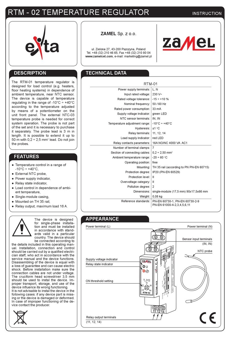
The temperature regulator RTD-01
is a 7-day programmable regulator
designed for electric oor heating
systems. It is operated by means of
a touch screen.
The regulator is mounted on a wall
in a junction box ¢60 x 60 mm. It is
compatible with oor sensors: SAS-
WELL 100k, SASWELL 10k, DEVI
15k, OJ12k, Eberle 33k, Ensto 47k,
FENIX 10k, TYCO 10k Teplolux 6k,
Warmup 12k, Aube 10k.
Supply terminals: N (1), L (2)
Power supply voltage: 100÷240 V AC
Nominal frequency: 50/60 Hz
Nominal power consumption: 1,5 W (STANDBY)
Battery backup: no
NTC sensor terminal: (6), (7)
Temperature sensor: NTC 10k lub 100k dla 25°C
Room temperature range: +5 ÷ +35°C
Floor temperature range: +5 ÷ +40°C
Operating temperature range: 0 ÷ +50°C
Temperature range during transport : -10 ÷ +60°C
Temperature measuring accuracy: ±0,5°C
Output terminals: (3), (4)
Type of output: voltage contact 1NO-16 A / 250 V AC
Number of connecting cables: 7
Cross section of connecting cables: 0,5 ÷ 2,5 mm2
Humidity: <90%, without condensation
Mounting: deeper junction box ¢ 60 mm x 60 mm
Casing material: engineering plastic, PC
Casing protection degree: IP21
Protection class: II
Overvoltage category: II
Nominal surge voltage: 2500 V
Pollution level of a regulator: 3 A level
Application environment: 2 pollution degree (domestic application
with standard air circulation)
Ball pressure temperature: 125°C
Dimensions: 81,5 x 81,5 x 21/41 mm ( height x width x depth )
Weight: 130 g
Reference standard: PN-EN 60730-1:2012
PN-EN 60730-2-9:2011
PN-EN 55014-1
PN-EN 55014-2
PN-EN 61000-3-2
PN-EN 61000-4-3
PN-EN 61000-4-11
PN-EN 61000-4-6
• 2,4” LCD display of 320x240 pxl
resolution
• Adjustment by means of a touch
screen
• Energy monitoring function
• Anti frost protection function
• Menu includes 11 languages: En-
glish, French, German, Dutch, Rus-
sian, Polish, Norwegian, Swedish,
Danish, Finnish, Romanian.
• Cooperation with NTC sensor of dif-
ferent manufacturers
• Blockades against children
• Holiday mode (holiday)
Temperature Regulator RTD-01 MANUAL INSTRUCTION
page: 1
ZAMEL Sp. z o.o.
ul. Zielona 27, 43-200 Pszczyna, Poland
tel. +48 32 449 15 00, +48 32 210 46 65, fax +48 (32) 210 80 04
www.zamel.com, e-mail: [email protected]
plik: Instrukcja RTD-01 v1.3 | mody kacja: 05.04.2016_plik: Instrukcja RTD-01 v1.3 | mody kacja: 05.04.2016_
plik: Instrukcja RTD-01 v1.3 en | modykacja: 20.11.2014
USAGE / MOUNTING SAFETY
REGULATOR’S MOUNTING PLACE
CONNECTION DIAGRAM
1 The device should be connected to a single phase in accordance with the standards applicable in the country.
2 The wiring diagram is specied in this manual instruction.
3 Activities connected with mounting, connection and adjustment should be performed by a qualied electrician, who is familiar with the
instruction and functions of the device.
4 Casing disassembly will void the warranty and can cause electric shock.
5 Before mounting, disassembly, cleaning or servicing operations power supply should be switched off from the mains and make sure
that the connection cables are not under voltage.
6 For mounting a screwdriver with a at bit with a diameter of 3,5 mm should be used.
7 Transport, storage and use of the device, in particular mounting of the regulator and the temperature sensor, have an inuence on its
proper operation.
8 Mounting the device in case of lacking of components, device damage or deformation is strongly prohibited.
9 In case of improper operation contact with the producer.
10 The regulator must not be covered and no elements or items can be hang on it (e.g. a towel).
11 Do not pour any liquids on the regulator.
12 Do not interrupt the power supply of the temperature regulator. It can can cause switching off the backlight of the screen and heating
control. The entered regulator’s adjustments will be saved.
13 The control and operation of the regulator by children or persons with physical, sensory or mental problems is strongly forbidden.
14 The regulator should be protected from shock and damage.
The regulator is designed to be used in an environment of two degree of contamination, i.e. to be used in domestic conditions
with standard air circulation.
1 The regulator should be mounted in a heated room – in a deep junction box ¢60 x 60 mm at a height of 120 cm from the heated
oor surface.
2 The regulator should be installed in a place not exposed to direct sunlight and in a little airy places.
3 Temperature and humidity in the mounting place should not exceed values given in technical parameters (0<T<50°C, humidity
RH > 90%).
L – phase wire
N – neutral wire
pos.3-4 - loading
pos. 5 – control input (Clock) – function not to be used in case
of RTD-01
pos. 6-7 – oor sensor
An example of mounting RTD-01 regulator
sunlight
Heating mat
1,2m
Regulator
page: 2
plik: Instrukcja RTD-01 v1.3 en | modykacja: 20.11.2014
PROGRAMME SETTINGS
Menu → Programme (Set program day). Choose the days of the week the changes will be made for → Next (by means of
arrows up / down) set the time and temperature zones). Conrm by OK.
Setting interface; There are 6 periods: morning, leaving home in the morning, returning in the noon, leaving home in the
afternoon, returning home in the evening and at night. Changes for 7 days can be made at the same time. Grey backlight of the
days of the week means changes in this operation cannot be made. It can be done after another entry into the Program.
Default settings of a period and temperature are as follows:
ENERGY COST REVIEW
Menu → Energy→ Cost and chose an appropriate period on the screen (today, yesterday, current day, current week, current
month, current year). Choose e.g. This week→ Next.
Estimated energy cost will be precise after heating cost adjustment.
ENERGY PARAMETERS SETTING
Menu → Energy→ Load. In this interface data can be entered subsequently into Load Sett and Tariff Sett → NEXT and
APPLY.
In each interface the adjustments should be entered.
TEMPERATURE UNIT SETTING
Menu → Setting → Scale → choose 0°C or 0°F and Apply.
SCREEN BACKLIGHT SETTING
Menu → Setting→ Video. In this interface the preferences should be chosen: background (black or blue), screen brightness
(3-2-1), stand-by brightness (3-2-1-0), parental control (switch on/switch off). Other functions should be chosen by Next and at
the end conrm by OK.
CHOICE OF TEMPERATURE MEASURING METHOD
Menu → Setting → Sensors mode. One method of measuring and control should be chosen (1. Room, 2. Floor, 3. All)
1. Room; Room sensor (internal); The regulator will read temperature from this sensor and will control the room temperature
2. Floor; External oor sensor (cable with a sensor).The regulator will read oor temperature from this sensor and will control its
temperature.
3. All; In this system the internal sensor is used to measure and control room temperature and the external sensor protects the
oor against overheating. If the oor temperature reaches the upper limit, the regulator will switch off the heating till the oor
temperature drops beneath the adjusted value.
Days
of the
week
Time Temp. Time Temp. Time Temp. Time Temp. Time Temp. Time Temp.
All 7 6:00 21 °C 8:00 16,5°C 12:00 21 °C 14:00 16,5°C 18:00 21 °C 22:00 16,5°C
page: 5
plik: Instrukcja RTD-01 v1.3 | mody kacja: 05.04.2016_plik: Instrukcja RTD-01 v1.3 | mody kacja: 05.04.2016_

Other Zamel Controllers manuals

Zamel exta SRP-05 User manual

Zamel

Zamel exta SRP-05 User manual

Zamel Exta RTM-02 User manual

Zamel

Zamel Exta RTM-02 User manual

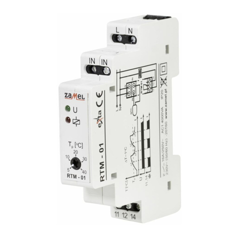
Zamel RTM - 01 User manual

Zamel

Zamel RTM - 01 User manual

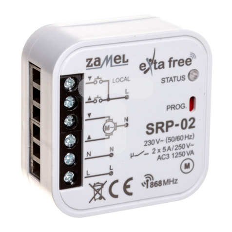
Zamel SRP-02 User manual

Zamel

Zamel SRP-02 User manual

Zamel NC60 User manual

Zamel

Zamel NC60 User manual

Zamel exta ZIM-12/25 User manual

Zamel

Zamel exta ZIM-12/25 User manual

Zamel Wi-Fi supla ROW-02 User manual

Zamel

Zamel Wi-Fi supla ROW-02 User manual

Zamel Extra Free RZB-02 User manual

Zamel

Zamel Extra Free RZB-02 User manual

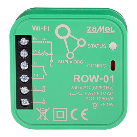
Zamel ROW-01 User manual

Zamel

Zamel ROW-01 User manual

Zamel RTD-02 User manual

Zamel

Zamel RTD-02 User manual

Zamel RNK-02 User manual

Zamel

Zamel RNK-02 User manual

Zamel exta life ROB-21 User manual

Zamel

Zamel exta life ROB-21 User manual

Zamel exta RTM-20 User manual

Zamel

Zamel exta RTM-20 User manual

Zamel RTP-01 User manual

Zamel

Zamel RTP-01 User manual

Zamel exta life SRM-22 User manual

Zamel

Zamel exta life SRM-22 User manual

Zamel ROB-01 User manual

Zamel

Zamel ROB-01 User manual

Zamel exta SRP-01/M User manual

Zamel

Zamel exta SRP-01/M User manual

Zamel exta MOM-02 User manual

Zamel

Zamel exta MOM-02 User manual

Zamel Extra Free ROB-01/12-24V User manual

Zamel

Zamel Extra Free ROB-01/12-24V User manual

Zamel exta ZCM-22 Series User manual

Zamel

Zamel exta ZCM-22 Series User manual

Zamel RNK-02 User manual

Zamel

Zamel RNK-02 User manual

Zamel GRM-10 User manual

Zamel

Zamel GRM-10 User manual

Zamel Exta Free EFC-02 Mini User manual

Zamel

Zamel Exta Free EFC-02 Mini User manual

Zamel RNK-02 User manual

Zamel

Zamel RNK-02 User manual

Popular Controllers manuals by other brands

Preferred Utilities Quanta-Flame 5004-890 quick start guide

Preferred Utilities

Preferred Utilities Quanta-Flame 5004-890 quick start guide

ChronTrol XT Series user guide

ChronTrol

ChronTrol XT Series user guide

Franklin Electric InlineSWC Quick setup guide

Franklin Electric

Franklin Electric InlineSWC Quick setup guide

V2 AYROS-24V series manual

V2

V2 AYROS-24V series manual

Powell FlexTrol Class E2 Instruction bulletin

Powell

Powell FlexTrol Class E2 Instruction bulletin

Archer VR6 Installation operation & maintenance

Archer

Archer VR6 Installation operation & maintenance

Mitsubishi Electric MELSEC-A Series user manual

Mitsubishi Electric

Mitsubishi Electric MELSEC-A Series user manual

MOTECK CB3T Product data sheet

MOTECK

MOTECK CB3T Product data sheet

OPTO 22 SNAP-PAC-S1 user guide

OPTO 22

OPTO 22 SNAP-PAC-S1 user guide

Genie RS485 user manual

Genie

Genie RS485 user manual

gefran 600 Installation and operation manual

gefran

gefran 600 Installation and operation manual

LS XBF-LD02S installation guide

LS

LS XBF-LD02S installation guide

Nevco 376 Operator instructions

Nevco

Nevco 376 Operator instructions

Siemens SIMATIC TI555 System manual

Siemens

Siemens SIMATIC TI555 System manual

PDC spas Accent Operation guide

PDC spas

PDC spas Accent Operation guide

Resol DeltaSol E manual

Resol

Resol DeltaSol E manual

Elan OLE XL Specifications

Elan

Elan OLE XL Specifications

Panasonic FP7 Series user manual

Panasonic

Panasonic FP7 Series user manual

manuals.online logo
manuals.online logoBrands
  • About & Mission
  • Contact us
  • Privacy Policy
  • Terms and Conditions

Copyright 2025 Manuals.Online. All Rights Reserved.