manuals.online logo
Brands
  1. Home
  2. •
  3. Brands
  4. •
  5. 3One data
  6. •
  7. Switch
  8. •
  9. 3One data IES7116G-8GS Series User manual

3One data IES7116G-8GS Series User manual

IES7116G-8GS Series
Managed Industrial Ethernet Switch
Quick Installation Guide
3onedata Co., Ltd.
【Package Checklist】
Please check whether the package and accessories are intact
while using the switch for the first time.
1. Industrial Ethernet switch 2. Quick installation guide
3. CD 4. Certification
5. Warranty card 6. DIN-Rail mounting attachment
If any of these items are damaged or lost, please contact our
company or dealers, we will solve it ASAP.
【Product Overview】
The product is full Gigabit managed DIN-Rail industrial
Ethernet switch. Module as follow: IES7116G-8GS (8
1000Base-SFP interfaces + 8 1000Base-T ports).
【Panel Design】
Top view, Bottom view and Rear view
Front view
1. Grounding screw
2. Relay alarm output terminal block
3. Console port
4. Power input terminal block
5. DIP switch
6. DIN-Rail mounting kit
7. Device running indicator RUN
8. Relay alarm indicator ALM
9. Power supply input status indicator P1/P2
10. 1000Base-SFP Gigabit Ethernet SFP slot
11. 10/100/1000Base-T(X) Ethernet port
12. Ethernet port status indicator:
【Mounting Dimension】
Unit: mm
【DIN-Rail Mounting】
For convenient usage in industrial environments, the product
adopts 35mm DIN-Rail mounting, mounting steps as below:
Check if the DIN-Rail mounting kit is installed firmly.Step 1 Insert the bottom of DIN-Rail mounting kit (one sideStep 2 with spring support) into DIN-Rail, and then insert
the top into DIN-Rail.
Tips:
Insert a little to the bottom, lift upward and then insert
to the top.
Check and confirm the product is firmly installed onStep 3 DIN-Rail, then mounting ends.
【Disassembling DIN-Rail】
Device power off.Step 1 After lift the device upward slightly, first shift out theStep 2 top of DIN-Rail mounting kit, then shift out the
bottom of DIN-Rail, disassembling ends.
Address:
3/B, Zone 1, Baiwangxin High Technology
Industrial Park, Xili, Nanshan District,
Shenzhen
Website:
www.3onedata.com
Tel:
+86 0755-26702688
Fax:
+86 0755-26703485
Note:
Don't place or install the device in area near water or
moist, keep the relative humidity of the device
surrounding between 5%~95% without condensation.
Before power on, first confirm the supported power
supply specification to avoid over-voltage damaging the
device.
The device surface temperature is high after running;
please don't directly contact to avoid scalding.
【Power Supply Connection】
DC power supply
The series devices provide 4 bits power
supply input terminal blocks and two
independent DC power supply systems
for PWR1 and PWR2. The power supply
has nonpolarity and anti-reverse functions,
it can normally operate after reverse connection. Power
supply range: 12~48VDC
Note:
Power ON operation: first connect power line to the
connection terminal of device power supply, then power
on.
Power OFF operation: first unpin the power plug, then
remove the power line, please note the operation order
above.
【Relay Connection】
Relay terminals are a pair of normally open
contacts in device alarm relay. They are open
circuit in normal non alarm state, closed when
any alarm information occurs. Such as: it's closed when power
off, and send out alarm. This series switches support 1
channel relay alarm information output, support DC power
alarm information or network abnormal alarm output, it can be
connected to alerting lamp, alarm buzzer, or other switching
value collecting devices for timely warning operating staffs
when alarm information occurs.
【DIP Switch Setting】
Provide 4-bits DIP switch for function setting,
where "ON" is enable valid terminal. Please
power off and power on after changing the status
of DIP switch. DIP switch define as follow:
1. Reboot 2. Restore factory setting
3. Reserved 4. Reserved
【Console Port Connection】
The device provides 1 channel procedure debugging port
based on serial port. The interface adopts RJ45 port, and can
conduct device CLI command line management after
connected to PC.
【Checking LED Indicator】
The function of each LED is described in the table as below:
LED
Status
Description
P1
ON
PWR1 is connected and running
normally
OFF
PWR1 is disconnected and running
abnormally.
P2
ON
PWR2 is connected and running
normally
OFF
PWR2 is disconnected and running
abnormally
ALM
ON
Power supply, port link alarm
OFF
Power supply, port link without alarm
RUN
ON
The device is powered on or the device
is abnormal.
OFF
The device is powered off or the device
is abnormal.
Blinking
System is running well.
Link/ACT
(1-16)
ON
Ethernet port connection is active.
Blinking
Data transmitted
OFF
Ethernet port connection is inactive.
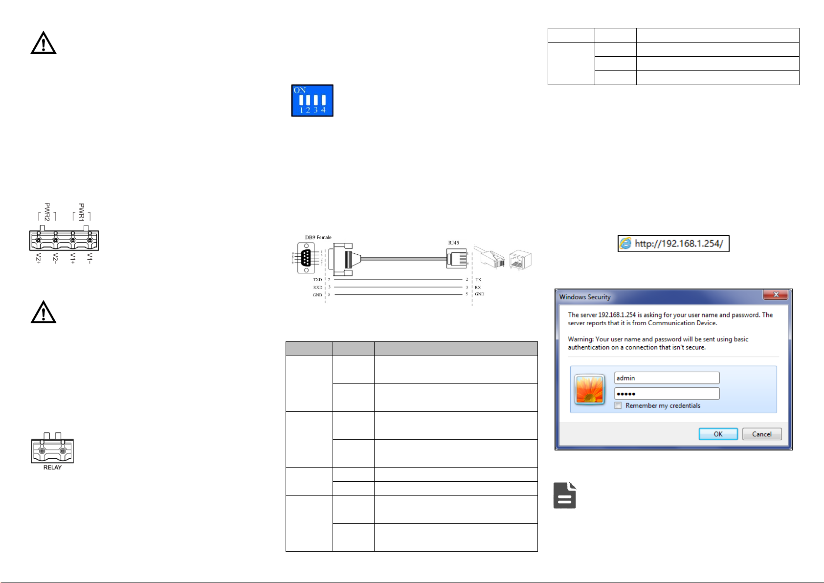
【Logging in to WEB Interface】
This device supports WEB management and configuration.
Computer can access the device via Ethernet interface. The
way of logging in to device’s configuration interface via IE
browser is shown as below:
Configure the IP addresses of computer and theStep 1 device to the same network segment, and the
network between them can be mutually accessed.
Enter device’s IP address in the address bar of theStep 2 computer browser.
Enter device’s username and password in the loginStep 3 window as shown below.
Click “OK”button to login to the WEB interface ofStep 4 the device.
Note:
The default IP address of the device is “192.168.1.254”.
The default username and password of the device is
“admin”.
If the username or password is lost, user can restore it to
factory settings via device DIP switch or management
software; all modified configurations will be cleared
after restoring to factory settings, so please backup
configuration file in advance.
Please refer to user manual for specific configuration
method of logging in to WEB interface and other
configurations about network management function.
【Specification】
Panel
1000M interface
1000Base-SFP, SFP slot
10/100/1000Base-T(X)
self-adapting RJ45 port, support
MDI/MDI-X self-adapting
Console port
RJ45
Alarm interface
2-pin 7.62mm pitch terminal block
Indicator
Power indicator, run indicator,
interface indicator and alarm
indicator
Exchange attributes
Backplane bandwidth
56G
Packet buffer size
12Mbit
MAC table size
16K
Power supply
Input power supply
12~48VDC
Access terminal
4-pin 7.62mm pitch terminal block
Consumption
No-load
10.99W@24VDC
Full-load
20.69W@24VDC
Working environment
Working temperature
-40℃~75℃
Storage temperature
-40℃~75℃
Working humidity
5%~95% (no condensation)
Protection grade
IP40 (metal shell)

Other 3One data Switch manuals

3One data SW4485I User manual

3One data

3One data SW4485I User manual

3One data IES6300TSN-8GT2GS-2LV User manual

3One data

3One data IES6300TSN-8GT2GS-2LV User manual

3One data TNS5800D Series User manual

3One data

3One data TNS5800D Series User manual

3One data IES206 Series User manual

3One data

3One data IES206 Series User manual

3One data IES615-2DI Series User manual

3One data

3One data IES615-2DI Series User manual

3One data IES7110 3GS Series User manual

3One data

3One data IES7110 3GS Series User manual

3One data IES206G-2GS User manual

3One data

3One data IES206G-2GS User manual

3One data IES6306 Series User manual

3One data

3One data IES6306 Series User manual

3One data TNS5800D User manual

3One data

3One data TNS5800D User manual

3One data IES6306 Series User manual

3One data

3One data IES6306 Series User manual

3One data TNS5000D Series User manual

3One data

3One data TNS5000D Series User manual

3One data IES5024 Series User manual

3One data

3One data IES5024 Series User manual

3One data IPS7112G-4GS-8GPOE User manual

3One data

3One data IPS7112G-4GS-8GPOE User manual

3One data IES6320 Series User manual

3One data

3One data IES6320 Series User manual

3One data IES2100SL Series User manual

3One data

3One data IES2100SL Series User manual

3One data IES1024 Series User manual

3One data

3One data IES1024 Series User manual

3One data TNS5800 Series User manual

3One data

3One data TNS5800 Series User manual

3One data ES1024 User manual

3One data

3One data ES1024 User manual

3One data TNS5800 Series User manual

3One data

3One data TNS5800 Series User manual

3One data ICS5530 Series User manual

3One data

3One data ICS5530 Series User manual

3One data IES6200-PN-16T4GS-2P48 User manual

3One data

3One data IES6200-PN-16T4GS-2P48 User manual

3One data IES5024-20F User manual

3One data

3One data IES5024-20F User manual

3One data TNS5800 Series User manual

3One data

3One data TNS5800 Series User manual

3One data ES1016 User manual

3One data

3One data ES1016 User manual

Popular Switch manuals by other brands

V-TAC VT-5003 Installation instruction

V-TAC

V-TAC VT-5003 Installation instruction

AMX Energy Management Modules RDM-3EM Installation sheet

AMX

AMX Energy Management Modules RDM-3EM Installation sheet

Manhattan 151252 user manual

Manhattan

Manhattan 151252 user manual

Eagle DCS A-10C Start-up

Eagle

Eagle DCS A-10C Start-up

Enterasys Vertical Horizon VH-2402-L3 Management guide

Enterasys

Enterasys Vertical Horizon VH-2402-L3 Management guide

GTC SSB6000 Series product manual

GTC

GTC SSB6000 Series product manual

Sangamo S250 Series Installation and user instructions

Sangamo

Sangamo S250 Series Installation and user instructions

Datacom DmSwitch 2000 Series installation guide

Datacom

Datacom DmSwitch 2000 Series installation guide

Targus ACH111AP user guide

Targus

Targus ACH111AP user guide

DAPAudio MP-100DBT user manual

DAPAudio

DAPAudio MP-100DBT user manual

FS S1900-16TP quick start guide

FS

FS S1900-16TP quick start guide

Siemens SENTRON SUPERSWITCH 3KL83 Series operating instructions

Siemens

Siemens SENTRON SUPERSWITCH 3KL83 Series operating instructions

Cabletron Systems Cabletron CyberSWITCH CSX5500 release note

Cabletron Systems

Cabletron Systems Cabletron CyberSWITCH CSX5500 release note

Miboxer K1 quick start guide

Miboxer

Miboxer K1 quick start guide

TRENDnet TEG-40080ES Quick installation guide

TRENDnet

TRENDnet TEG-40080ES Quick installation guide

Techly HDMI-2128KT quick start guide

Techly

Techly HDMI-2128KT quick start guide

KVMSwitchTech HDMI-PIP-4P-MINI instruction manual

KVMSwitchTech

KVMSwitchTech HDMI-PIP-4P-MINI instruction manual

Avocent 115B Installer/user guide

Avocent

Avocent 115B Installer/user guide

manuals.online logo
manuals.online logoBrands
  • About & Mission
  • Contact us
  • Privacy Policy
  • Terms and Conditions

Copyright 2025 Manuals.Online. All Rights Reserved.