Dru DVS-2 User guide

INSTALLATIEVOORSCHRIFT EN GEBRUIKERSHANDLEIDING
INSTRUCTIONS FOR INSTALLATION AND OPERATION
INSTALLATIONSVORSCHRIFT UND GEBRAUCHSANWEISUNG
INSTRUCTIONS D’INSTALLATION ET MODE D’EMPLOI
DVS-2
ODEON
OPERA
BASTILLE
ELYSÉE
Bewaar dit document zorgvuldig
Please retain this document carefully
Bewahren Sie dieses Dokument sorgfältig auf
Conservez soigneusement cette notice
957.554.00
DRU VERWARMING B.V.
HOLLAND


Nederlands
1
INHOUD
Woord vooraf . . . . . . . . . . . . . . . . . . . . . . . . . . . . . .2
Uitpakken . . . . . . . . . . . . . . . . . . . . . . . . . . . . . . . . .2
Aansluiten . . . . . . . . . . . . . . . . . . . . . . . . . . . . . . . . .2
Installatievoorschrift . . . . . . . . . . . . . . . . . . . . . . . . .2
Gassoort . . . . . . . . . . . . . . . . . . . . . . . . . . . . . . . . .2
Belangrijk . . . . . . . . . . . . . . . . . . . . . . . . . . . . . . . . .2
Algemeen . . . . . . . . . . . . . . . . . . . . . . . . . . . . . . . . .2
Installatie aan een wand van onbrandbaar materiaal .2
De standaard geveldoorvoer . . . . . . . . . . . . . . . . . . .2
Montage van de geveldoorvoer . . . . . . . . . . . . . . . . .2
De geveldoorvoer met telescopische inlaatpijp . . . . .3
Installatie van de geveldoorvoer met
telescopische inlaatpijp . . . . . . . . . . . . . . . . . . . . . . .3
Installatie aan een wand van brandbaar materiaal . . .3
Plaatsen van de aluminium schermplaat . . . . . . . . . .3
Plaatsen van de convector . . . . . . . . . . . . . . . . . . . .3
Aansluiting van de gastoevoer . . . . . . . . . . . . . . . . . .4
Gloeikooltjes . . . . . . . . . . . . . . . . . . . . . . . . . . . . . .4
Monteren van de thermostaatvloer . . . . . . . . . . . . .4
Plaatsen van de mantel . . . . . . . . . . . . . . . . . . . . . . .4
Vloerplaat . . . . . . . . . . . . . . . . . . . . . . . . . . . . . . . . .4
In bedrijf stellen . . . . . . . . . . . . . . . . . . . . . . . . . . . .4
Kleinstand . . . . . . . . . . . . . . . . . . . . . . . . . . . . . . . . .4
Waakvlambrander . . . . . . . . . . . . . . . . . . . . . . . . . . .4
Gebruikershandleiding . . . . . . . . . . . . . . . . . . . . . . .5
Aansteken . . . . . . . . . . . . . . . . . . . . . . . . . . . . . . . . .5
Temperatuur regelen . . . . . . . . . . . . . . . . . . . . . . . .5
Waakvlamstand . . . . . . . . . . . . . . . . . . . . . . . . . . . . .5
Uitschakelen . . . . . . . . . . . . . . . . . . . . . . . . . . . . . . .5
Belangrijk . . . . . . . . . . . . . . . . . . . . . . . . . . . . . . . . .5
Algemene opmerkingen . . . . . . . . . . . . . . . . . . . . . .6
Onderhoud en reiniging . . . . . . . . . . . . . . . . . . . . . .6
Verkleuring van wanden en plafonds . . . . . . . . . . . . .6
Eerste maal stoken . . . . . . . . . . . . . . . . . . . . . . . . . .6
Extra bescherming . . . . . . . . . . . . . . . . . . . . . . . . . .6
Afdanken . . . . . . . . . . . . . . . . . . . . . . . . . . . . . . . . .6
Garantie . . . . . . . . . . . . . . . . . . . . . . . . . . . . . . . . . .6
(Voor België de garantiekaart op blz. 19 en 23 invullen)
Technische gegevens . . . . . . . . . . . . . . . . . . . . . . . .27
INHOUD
Garantiebepalingen
• DRUVerwarming B.V. garandeert de goede werking van het toestel en staat er voor in dat het toestel met de grootste zorg is vervaardigd van deugdelijk
materiaal.
• De garantie geldt gedurende 1 jaar na datum van aankoop.
• Onder de garantie vallen alle gebreken, die een gevolg zijn van fouten in de constructie of voor de constructie gebruikte onderdelen.
• DRU Verwarming verplicht zich gedurende de garantieperiode gratis vervangende onderdelen te leveren. Het 1ste jaar van de garantietermijn zullen - dit
ter beoordeling van DRUVerwarming B.V. - geen kosten in rekening worden gebracht.
• De garantie vervalt als storingen het gevolg zijn van foutieve installatie, van verkeerd gebruik of onderhoud van onderdelenvervanging door andere dan
originele onderdelen of van plaatsing of reparaties door onbevoegden.
• Indien het opsturen van het apparaat naar de fabriek noodzakelijk is dient dit franco te gebeuren. Het garantiebewijs s.v.p. meesturen.
• Wanneer u aanspraak wilt maken op fabrieksgarantie, wilt u dan eerst contact opnemen met uw installateur.
• Wilt u bij uw garantiebewijs ook de rekening van uw leverancier bewaren. Bij serviceverlening zal men hier naar vragen.
DRU Verwarming B.V.
GARANTIEBEWIJS
Wilt u dit garantiebewijs volledig invullen en samen met de rekening bij uw toestel bewaren.
Invullen in blokletters s.v.p.
Type: . . . . . . . . . . . . . . . . . . . . . . . . . . . . . . . . . Aankoopdatum: . . . . . . . . . . . . . . . . . . . . . . . . . .
Kleur: . . . . . . . . . . . . . . . . . . . . . . . . . . . . . . . . . Serienummer (op typeplaat): . . . . . . . . . . . . . . . .
Koper: Leverancier:
Naam . . . . . . . . . . . . . . . . . . . . . . . . . . . . . . . . . Naam . . . . . . . . . . . . . . . . . . . . . . . . . . . . . . . . .
Adres . . . . . . . . . . . . . . . . . . . . . . . . . . . . . . . . . Adres . . . . . . . . . . . . . . . . . . . . . . . . . . . . . . . . .
Postcode . . . . . . . . . . . . . . . . . . . . . . . . . . . . . . Postcode . . . . . . . . . . . . . . . . . . . . . . . . . . . . . . .
Plaats . . . . . . . . . . . . . . . . . . . . . . . . . . . . . . . . . Plaats . . . . . . . . . . . . . . . . . . . . . . . . . . . . . . . . . .
IN GEVAL VAN STORINGEN, DIENT U ZICH ALTIJD TOT UW LEVERANCIER TE WENDEN.
DRU Verwarming garandeert de goede werking van dit apparaat bij vakkundige installatie
en gebruik volgens de gebruiksaanwijzingen.
DVS-2

Woord vooraf
Geachte klant,
Vriendelijk bedankt voor de aankoop van dit DRU
product. Onze producten zijn ontwikkeld en gefabriceerd
volgens de hoogst mogelijke kwaliteits-, prestatie- en
veiligheidseisen. Hierdoor kunt u rekenen op jarenlang
probleemloos gebruiksplezier.
In dit boekje vindt u instructies voor installatie en gebruik
van uw nieuwe toestel. Lees de instructies en gebruikers-
handleiding goed door, zodat u zich vertrouwd maakt met
het toestel.Wilt u meer ondersteuning, neem dan contact
op met uw leverancier.
Uitpakken
Wanneer u klaar bent met uitpakken, dient de verpakking
via de reguliere weg te worden afgevoerd.
Aansluiten
Dit toestel dient te worden aangesloten door een bevoegd
installateur.
INSTALLATIEVOORSCHRIFT
Gassoort
Dit toestel is geschikt voor aardgas G20 of aardgas G25.
Controleer of de gassoort en de gasdruk ter plaatse over-
eenkomen met de vermelding op het typeplaatje. Houdt u
aan de gasinstallatievoorschriften en eventuele plaatselijke
voorschriften. Het toestel dient door een bevoegd installa-
teur te worden aangesloten.
Om het toestel te laten werken op butaan of propaan
dient het omgebouwd te worden door een bevoegd instal-
lateur. Een ombouwset is via hem te bestellen.
Belangrijk
• Zorg ervoor dat evt. overgordijnen of andere brandbare
materialen minstens 50 cm van het toestel verwijderd zijn.
• Let op! Aanraking van hete delen kan brandblaren veroor-
zaken!
• Het toestel dient door een erkend installateur
geïnstalleerd te worden (in België volgens NBN D 51-003).
• Het plaatsen van een z.g. stoffilter op of onder de mantel
is niet toegestaan.
• Natte kleding, handdoeken e.d. niet op de kachel te
drogen hangen!
Algemeen
Het toestel kan zowel aan een wand van onbrandbaar
materiaal (b.v. steen of beton), als aan een wand van brand-
baar materiaal (b.v. hout) geïnstalleerd worden.
Installatie aan een wand van onbrandbaar
materiaal
Bepaal de plaats van de convector die tegen een buiten-
gevel en staand op de vloer geïnstalleerd moet worden.
Leg de aluminium vloerplaat op de vloer en zet de
convector, zonder mantel, erop.
Schuif het toestel tegen de muur op de gewenste plaats.
Op de achterkant van de convector is de montageplaat
gemonteerd ((2) fig.1) die nu tegen de muur aan ligt.
Te ken de bovenkant en een zijkant van de montageplaat
op de muur af.
Na demontage van de montageplaat kan deze vervolgens
als aftekenmal gebruikt worden voor het gat in de gevel.
Om de mantel om het binnenwerk te kunnen hangen
moet men rekening houden dat tussen een eventuele ven-
sterbank en het toestel een vrije ruimte van minimaal 25
mm noodzakelijk is.
De standaard geveldoorvoer
Maak een horizontaal gat in de muur met een diameter
van ø 230mm voor doorvoering van de inlaatpijp. Zorg er
voor dat de muurdoorvoer ongeveer 2º op afschot ligt.
De standaard geveldoorvoer is geschikt voor wanddiktes
van 50-330 mm en de standaard verlengde doorvoer voor
wanddiktes van 50-600 mm.Afhankelijk van de wanddikte
dienen de in- en uitlaatpijp op lengte te worden gemaakt n.l.
• lengte inlaatpijp = wanddikte + 20 mm.
• lengte uitlaatpijp = wanddikte + 70 mm.
De aan het muurrooster gemonteerde trekstangen kunnen
na montage van de geveldoorvoer worden ingekort.
Montage van de geveldoorvoer (fig. 1)
Schuif de inlaatpijp (1) in de muuropening.
Breng vanaf de buitenzijde het muurrooster met de twee
trekstangen (4) in de inlaatpijp.
Hang de montageplaat (2) om de inlaatpijp en druk deze
vlak tegen de muur.
Het merkteken "TOP" boven houden bij het plaatsen van
het muurrooster.
INSTALLATIE VOORSCHRIFT
2
358
38c-701
15
2
4
3
6
6
3
1. Inlaatpijp
2. Montageplaat
3. Bevestigingsbeugel
4.Trekstang
5. Pakkingsring
6. Bevestigingsbout
fig. 1

Nederlands
Schuif de twee bevestigingsbeugels (3) zodanig over de
trekstangen dat ze om de rand van de montageplaat en
de inlaatpijp haken.
Met twee moeren de muurdoorvoer vastdraaien terwijl
tevens de montageplaat en het muurrooster in de goede
positie gedraaid worden (de twee bouten op de monta-
geplaat en de trekstangen horizontaal).
De montageplaat op de plaats schuiven die vooraf op de
muur is afgetekend.
De geveldoorvoer met telescopische inlaatpijp
Deze is geschikt voor wanddiktes van 250 - 440 mm zon-
der inkorten van de inlaatpijpdelen. Door de pijpdelen in
te korten is deze geveldoorvoer geschikt te maken voor
wanddiktes van 70 tot 250 mm. De uitlaatpijp dient op
lengte te worden gemaakt volgens tabel. De aan het
muurrooster gemonteerde trekstangen kunnen na monta-
ge van de geveldoorvoer worden ingekort.
Indien voor wanddiktes van 70 tot 250 mm de telescopi-
sche inlaatpijp wordt toegepast dienen beide pijpdelen te
worden ingekort n.l.:
• het inlaatpijpdeel aan de muurroosterzijde gelijk aan de
wanddikte
• het pijpdeel aan de toestelzijde op een lengte = de wand-
dikte - 20 mm.
LET OP: de pijpdelen niet afknippen aan de zijde waar
de bevestigingsbeugeltjes zijn aangebracht.
Installatie van de geveldoorvoer met
telescopische inlaatpijp (fig. 1)
Breng het muurrooster met de daaraan gemonteerde
inlaatpijphelft van buitenaf in de gemaakte muuropening
met "Top" naar boven bij het plaatsen van het muur-
rooster. Schuif de andere helft van de inlaatpijp door de
montageplaat (2) en zorg daarbij dat de ingelaste bevesti-
gingsbeugels (3) op de horizontale hartlijn liggen (zie de
merktekens in de montageplaat) en om de omgezette
montageplaatrand haken.
Schuif de inlaatpijp helft van binnenuit door de gemaakte
muuropening in het reeds aangebrachte inlaatpijp deel.
Zorg daarbij dat de twee trekstangen (4) door de bevesti-
gingsbeugels (3) steken. De montageplaat aandrukken tot
tegen de wand. Breng de moeren aan op de trekstangen
(4) en zet deze tegen de bevestigingsbeugels (3) handvast.
Installatie aan een wand van brandbaar
materiaal
Het aftekenen van de muurdoorvoer op de wand kan
hetzelfde als bij een wand van onbrandbaar materiaal.
Maak op het hart van het ronde gat in de montageplaat
een vierkante opening door de gevel van 280 mm.
Bij een dubbele wand de spouw goed opvullen zodat de
delen niet samengedrukt worden.
Bevestig aan de buitenkant van de gevel m.b.v. 4 schroe-
ven de extra siluminplaat.
De extra plaat voor doorvoer brandbare wand wordt op
bestelling geleverd.
De montage van de muurdoorvoer is verder zoals
beschreven bij montage aan een wand van onbrandbaar
materiaal.
N.B.Voor de berekening van de lengte van de in- en uit-
laatpijp dient ook de dikte van siluminplaat 15 te worden
meegeteld.
Plaatsen van de aluminium schermplaat
De aluminium schermplaat dient bij installatie van
de convector onder de voet van het binnenwerk
geplaatst te worden. De plaat zo ver naar achteren
schuiven dat de voorzijde gelijk ligt met de voor-
zijde van de plaatstalen voet.
Plaatsen van de convector
Schuif de uitlaatpijp in het muurrooster en zet de convec-
tor op de vloerschermplaat.
De convector tegen de wand schuiven met de uitlaat
over de uitlaatpijp en met de bevestigingsbeugels over de
twee bouten van de montageplaat.
Twee moeren aanbrengen en licht vastzetten.
INSTALLATIE VOORSCHRIFT
3
DVS-2
38c-700
fig. 2
Detail muur bevestiging

Aansluiting van de gastoevoer
De aansluiting is 3/8" BSP binnendraad. Gebruik in de toe-
voerleiding een gekeurde aansluitkraan met koppeling
(voor Belgie moet deze B.G.V. gekeurd zijn). De aansluit-
kraan met koppeling dient buiten de mantel te worden
geplaatst.Verder geldt:
• Ontlucht de toevoerleiding voordat het toestel wordt
vastgekoppeld.
• De bedieningskraan mag niet verdraaid worden bij het
aansluiten aan de gastoevoerleiding.
•Vermijd spanningen op de bedieningskraan en leidingen.
• Controleer de aansluitingen op gasdichtheid.
Gloeikooltjes
Deze zijn vanuit de fabriek reeds gemonteerd.Wanneer
deze moeten worden vervangen ga dan als volgt te werk:
• Verwijder de 8 moeren.
• Glasraam afnemen.
• Verwijder de kapotte gloeikooltjes.
• Plaats de gloeikooltjes gelijkmatig verdeeld op het raam-
werk in de verbrandingskamer (fig. 3).
• Glasraam terugplaatsen.
• 8 moeren vastdraaien.
Monteren van de thermostaatvoeler (fig. 3)
Voor de thermostaatvoeler is een voelerhouder bijgeleverd
die naast de convector op de plint of laag tegen de muur
bevestigd dient te worden.
Plaatsen van de mantel
De mantel over het binnenwerk hangen met de achterrand
in de mantelsteunen.
Tevens dient het voorfront over de centreerpennen van de
voetsteunen te vallen.
Vloerplaat
De vloerplaat onder het toestel schuiven met de uitsparing-
en om de voeten van het binnenwerk.
In bedrijf stellen
Het toestel is door de fabriek ingericht voor de gassoort
zoals op het typeplaatje is aangegeven.
De thermostaat regelt modulerend tussen ,volstand" en
,kleinstand" en bij een geringe warmtebehoefte in twee
posities, n.l. ,kleinstand" of ,uit". Hierbij blijft de waakvlam
steeds branden. De kleinstand kan alleen worden gecon-
troleerd wanneer de kamertemperatuur hoger is dan ca.
15° C (60° F).
Kleinstand
De kleinstand is ingesteld op ± 20 % van het volverbruik.
De kleinstandschroef is geheel ingedraaid en voorzien van
de juiste kleinstandboring. Deze is niet instelbaar.
Waakvlambrander
De waakvlambrander heeft bij levering het juiste verbruik
d.m.v. een spuitstuk dat zich in de waakvlambrander bevindt.
De waakvlambrander behoeft niet te worden ingesteld.
4
INSTALLATIE VOORSCHRIFT
38c-993
fig. 3
38c-709
100
80
fig. 4

GEBRUIKERSHANDLEIDING
Aansteken
De druktoets A (symbool )
indrukken en ingedrukt houden.
Daarna tevens de ontsteektoets E
(symbool ) één of twee maal
indrukken waardoor de waakvlam-
brander ontstoken wordt.
Controleer of de waakvlam brandt.
(achter het glasraampje aan de voor-
zijde). Indien de waakvlam brandt, de
druktoets A nog ca. 10 sec. geheel
ingedrukt houden. Daarna toets A
loslaten en controleren of de waak-
vlam blijft branden.Afhankelijk van
de stand van de thermostaatknop D en de kamertempera-
tuur kan de hoofdbrander onmiddellijk na het loslaten van
toets A door de waakvlam ontstoken worden.
Temperatuur regelen
De stand van de thermostaatknop D bepaalt de tempera-
tuur in de kamer. Stand 7 (met 7 tegenover het indicatie-
punt C) geeft de hoogste temperatuur en stand 1 de laagste.
De thermostaat regelt modulerend tussen "volstand" en
"kleinstand" van de brander en bij een kleine warmtebe-
hoefte tussen "kleinstand" en "N".
De thermostaat houdt de kamer automatisch op de
gewenste ingestelde temperatuur.
Het is geen enkel bezwaar om het toestel ‘s nachts te
laten doorbranden; het is volledig beveiligd.
De thermostaat is voorzien van een vorstbeveiliging. Dit is
stand N op de thermostaatknop D. Bij een omgevingstem-
peratuur van onder de 10ºC wordt het ventiel automa-
tisch geopend, waardoor het toestel de ruimte verwarmd
tot 10ºC. Indien dit niet gewenst is, dient het toestel uitge-
schakeld te worden
Uitschakelen
Druktoets B (met symbool o ) indrukken. De gastoevoer
naar de hoofd- en de waakvlambrander is dan gesloten.
Belangrijk
Een ingebouwde veiligheidsvergrendeling treedt in werking
wanneer het toestel op ,,UIT" (gesloten stand) wordt
gezet.Wacht daarom 5 minuten alvorens het toestel
opnieuw te ontsteken. Probeer binnen deze tijd niet de
aansteekknop in te drukken, daar deze door de veiligheids-
vergrendeling geblokkeerd is. Forceer de knop niet, omdat
het mechanisme dan kan worden beschadigd.
Nederlands
GEBRUIKERSHANDLEIDING
E
B
A
C
D
✂
REGISTRATIEKAART
DRU Verwarming kan alleen garantie verlenen indien deze registratiekaart volledig en duidelijk
in blokletters en binnen 8 dagen opgestuurd is aan DRU Verwarming B.V.
Type: . . . . . . . . . . . . . . . . . . . . . . . . . . . . . . . . . . . . Aankoopdatum: . . . . . . . . . . . . . . . . . . . . . . . . . . . . . . .
Kleur: . . . . . . . . . . . . . . . . . . . . . . . . . . . . . . . . . . . Serienummer (op typeplaat): . . . . . . . . . . . . . . . . . . . . .
Koper: Detaillist/installateur:
Naam . . . . . . . . . . . . . . . . . . . . . . . . . . . . . . . . . . . Naam . . . . . . . . . . . . . . . . . . . . . . . . . . . . . . . . . . . . . . .
Adres . . . . . . . . . . . . . . . . . . . . . . . . . . . . . . . . . . . Adres . . . . . . . . . . . . . . . . . . . . . . . . . . . . . . . . . . . . . . .
Postcode . . . . . . . . . . . . . . . . . . . . . . . . . . . . . . . . . Postcode . . . . . . . . . . . . . . . . . . . . . . . . . . . . . . . . . . . .
Plaats . . . . . . . . . . . . . . . . . . . . . . . . . . . . . . . . . . . . Plaats . . . . . . . . . . . . . . . . . . . . . . . . . . . . . . . . . . . . . . .
Telefoon . . . . . . . . . . . . . . . . . . . . . . . . . . . . . . . . . Telefoon . . . . . . . . . . . . . . . . . . . . . . . . . . . . . . . . . . . . .
Hartelijk dank voor uw medewerking.

ALGEMENE OPMERKINGEN
Onderhoud en reiniging
Periodiek onderhoud dient door een bevoegd installateur
te worden uitgevoerd. Het gasregelblok mag niet worden
gesmeerd. Het verdient aanbeveling om vóór en tijdens het
stookseizoen het toestel enkele malen stofvrij te maken.
Bij het reinigen van de mantel geen bijtende of schurende
middelen gebruiken. Lakbeschadigingen, bijvoorbeeld door
het plaatsen van voorwerpen op of tegen de mantel, vallen
buiten de garantie.
U kunt de mantel verwijderen door deze op te tillen en
naar voren te schuiven.
De binnenkant van het glasraam kunt U schoonmaken met
een vochtige doek of met een niet-krassend reinigingsmiddel.
Het glasraam kunt U wegnemen na het verwijderen van de
vleugelmoeren.
Een gebarsten of gebroken ruit dient vervangen te worden
alvorens het toestel opnieuw in gebruik te nemen.
Wanneer een gloeikooltje is gebroken of door andere oor-
zaken zich niet op de juiste plaats bevindt, dient dit direkt
hersteld te worden.
Let op: Bij het vervangen van het thermokoppel moet de
wartel in het gasregelblok handvast gedraaid worden,
waarna deze met een steeksleutel een kwartslag aange-
draaid moet worden.
Ver kleuring van wanden en plafonds
Bruinverkleuring is een vervelend probleem en is moeilijk
op te lossen. Bruinverkleuring kan worden veroorzaakt
door onder andere stofverbranding veroorzaakt door te
weinig ventilatie, door het roken van sigaretten of het
branden van kaarsen.
Deze problemen kunnen worden voorkomen door:
Het vertrek waar het toestel zich bevind goed te ventile-
ren. Een goede richtlijn hiervoor is:
Bij nieuwbouw : 3.24 m3/ uur per m2
vloeroppervlak van een vertrek.
Bij bestaande bouw : 25.20 m3/ uur voor een vertrek.
Maak zo weinig mogelijk gebruik van kaarsen en olielam-
pjes en houd het verbrandingslontje zo kort mogelijk.
Deze "sfeerbrengers" zorgen voor aanzienlijke hoeveelhe-
den vervuilde en ongezonde roetdeeltjes in uw woning.
Rook van sigaretten en sigaren bevat o.a. teerstoffen die bij
verhitting eveneens op koudere en vochtige muren zullen
neerslaan. Bij een nieuw gemetselde schouw of na een ver-
bouwing wordt aanbevolen minimaal 6 weken te wachten
voordat men gaat stoken, het bouwvocht moet namelijk
geheel verdwenen zijn uit wanden, vloer en plafond.
Eerste maal stoken
Tijdens de eerste maal stoken kan er een onaangename
geur ontstaan, die wordt veroorzaakt door het uitdampen
van de lak. Dit verdwijnt na enkele uren. Daarom raden wij
u aan het toestel de eerste maal op de hoogste stand te
stoken terwijl u tevens het vertrek waarin de kachel staat
goed ventileert.
Extra bescherming
Indien het toestel in een vertrek geïnstalleerd wordt waar
jonge kinderen of hulpbehoevende mensen zonder toezicht
verblijven, is het wenselijk het toestel af te schermen.
Afdanken
Indien u het toestel vervangt of verwijdert, moet u het
toestel via de reguliere weg afvoeren.Voordat tot demon-
tage wordt overgegaan eerst de aansluitkraan met koppe-
ling dichtdraaien. De koppeling tussen aansluitkraan en toe-
stel losdraaien. Het gehele toestel kan nu worden gede-
monteerd en afgevoerd.
Garantie
De REGISTRATIEKAART gelieve binnen 8 dagen na aan-
koop in te vullen en op te sturen in een envelop zonder
postzegel naar het onderstaande adres.
DRU VERWARMING B.V.
ANTWOORDNUMMER 4551
6920 ZX DUIVEN
Het GARANTIEBEWIJS (blz. 1) kunt u zelf behouden.
De garantie gaat in op het ogenblik, dat de volledig ingevul-
de registratiekaart door DRU Verwarming is ontvangen.
VOOR BELGIË DE KAART INVULLEN OP PAGINA 19 EN 23
EN STUREN AAN DRU BELGIUM.
ALGEMENE OPMERKINGEN
✂
VERSTUREN IN EEN
ENVELOP

English
7
CONTENTS
CONTENTS
Foreword . . . . . . . . . . . . . . . . . . . . . . . . . . . . . . . . .8
Unpacking . . . . . . . . . . . . . . . . . . . . . . . . . . . . . . . . .8
Connection . . . . . . . . . . . . . . . . . . . . . . . . . . . . . . . .8
Instructions for installation . . . . . . . . . . . . . . . . . . . .8
Type of gas . . . . . . . . . . . . . . . . . . . . . . . . . . . . . . . .8
Important . . . . . . . . . . . . . . . . . . . . . . . . . . . . . . . . .8
General . . . . . . . . . . . . . . . . . . . . . . . . . . . . . . . . . . .8
Installing against a non-combustible wall . . . . . . . . . .8
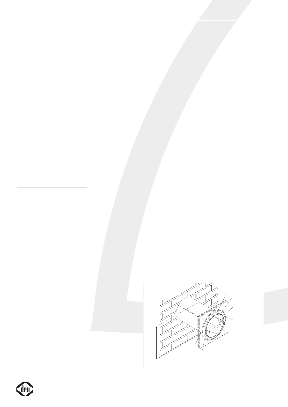
The standard wall duct . . . . . . . . . . . . . . . . . . . . . . .8
Mon fitting the wall duct . . . . . . . . . . . . . . . . . . . . . .8
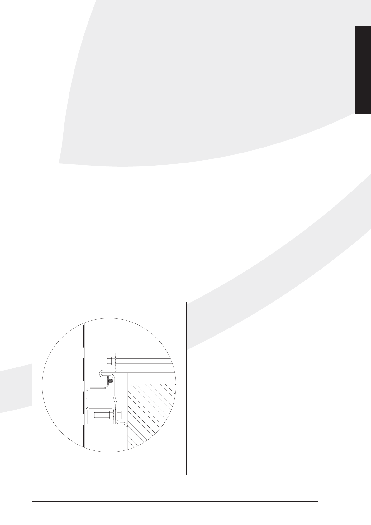
The exterior wall duct with telescopic inlet pipe . . .9
Installation of the wall duct with
telescopic inlet pipe . . . . . . . . . . . . . . . . . . . . . . . . .9
Installation against a combustible wall . . . . . . . . . . . .9
Positioning the aluminium shield . . . . . . . . . . . . . . . .9
Positioning the convector . . . . . . . . . . . . . . . . . . . . .9
Connection of the gas supply . . . . . . . . . . . . . . . . .9
Glowing coals . . . . . . . . . . . . . . . . . . . . . . . . . . . . . .9
Fitting the thermostat phial . . . . . . . . . . . . . . . . . . .10
Floor plate . . . . . . . . . . . . . . . . . . . . . . . . . . . . . . .10
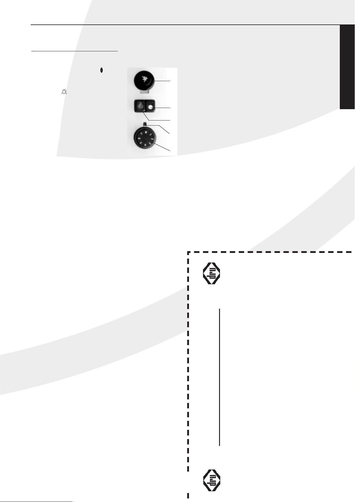
Operations . . . . . . . . . . . . . . . . . . . . . . . . . . . . . . .10
The low setting . . . . . . . . . . . . . . . . . . . . . . . . . . . .10
Pilot light burner . . . . . . . . . . . . . . . . . . . . . . . . . . .10
Operating instructions . . . . . . . . . . . . . . . . . . . . . .10
Lighting . . . . . . . . . . . . . . . . . . . . . . . . . . . . . . . . . .10
Temperature controle . . . . . . . . . . . . . . . . . . . . . . .10
Pilot light setting . . . . . . . . . . . . . . . . . . . . . . . . . . .10
Switching off . . . . . . . . . . . . . . . . . . . . . . . . . . . . . .10
Important . . . . . . . . . . . . . . . . . . . . . . . . . . . . . . . .10
General notes . . . . . . . . . . . . . . . . . . . . . . . . . . . . .11
Gas safety regulations (for installation & use), 1998 11
Cleaning and Maintenance . . . . . . . . . . . . . . . . . . . .11
Discoloration of walls and ceiling . . . . . . . . . . . . . .11
Lighting the heater for the first time . . . . . . . . . . . .11
Extra protection . . . . . . . . . . . . . . . . . . . . . . . . . . .11
Disposal . . . . . . . . . . . . . . . . . . . . . . . . . . . . . . . . .11
Guarantee . . . . . . . . . . . . . . . . . . . . . . . . . . . . . . . .12
Technical data . . . . . . . . . . . . . . . . . . . . . . . . . . . . .27
Conditions of warranty
• This appliance has been manufactured and tested by DRU verwarming BV of The Netherlands with utmost care.
• Subject to the conditions set out on this card DRU guarantees the proper operation of this vented room heater to the original purchaser for a period of
one year after date of purchase.
• Subject to the conditions set out on this card, the cast iron combustion chamber of your DRU vented room heater carries a full guarantee to the original
purchaser for a period of ten years after date of purchase.
• The guarantee does not cover the normal wear and tear, damage due to incorrect treatment, changes of the equipment or unauthorised installations and
repairs. No liability is assumed by DRU for removal or (re)installation labor costs.
• Under no circumstances shall DRU be liable for incidental, consequential, special or contingent damages or expenses arising directly or indirectly from any
defect in the product or any component or from the use thereof.The remedies set forth herein are the exclusive remedies available to the user and are in
lieu of all other remedies. Subject to specific state laws some of the above limitations or exclusions may not apply to you.
DRU Verwarming B.V.
WARRANTY CARD
Please complete this card and keep it with the invoice to verify purchase date
and to establish the warranty period*.
Model: . . . . . . . . . . . . . . . . . . . . . . . . . . . . . . . . Date: . . . . . . . . . . . . . . . . . . . . . . . . . . . . . . . . . .
Colour: . . . . . . . . . . . . . . . . . . . . . . . . . . . . . . . Serial No.: . . . . . . . . . . . . . . . . . . . . . . . . . . . . . .
Type of Gas: Natural Gas ❑L.P.G.❑(please check)
Customer: Dealer/Installer
Name . . . . . . . . . . . . . . . . . . . . . . . . . . . . . . . . . Name . . . . . . . . . . . . . . . . . . . . . . . . . . . . . . . . .
Address . . . . . . . . . . . . . . . . . . . . . . . . . . . . . . . Address . . . . . . . . . . . . . . . . . . . . . . . . . . . . . . . .
City . . . . . . . . . . . . . . . . . . . . . . . . . . . . . . . . . City . . . . . . . . . . . . . . . . . . . . . . . . . . . . . . . . . . .
State . . . . . . . . . . . . . . . . . . . . . . . .ZIP . . . . . State . . . . . . . . . . . . . . . . . . . . . . . . .ZIP . . . . . .
Province . . . . . . . . . . . . . . . . . . . . . .P.C. . . . . . Province . . . . . . . . . . . . . . . . . . . . . .P.C. . . . . . .
Telephone ( . . . . . . . . .) . . . . . . . . . . . . . . . . . .
*FOR SERVICE UNDER THIS WARRANTY CONTACT YOUR DEALER/INSTALLER.
DRU warrants the proper functioning of this vented roomheater if installed by a qualified installer and if used in
strict accordance with the manufacturers operating instructions
DVS-2

Foreword
Dear Customer,
We would like to thank you for buying this DRU product.
Our products have been designed and produced to meet
the highest possible quality, performance and safety
requirements, allowing you to enjoy years of problem-free
use.
In this booklet you will find instructions for the installation
and use of your new appliance. Please read these instruc-
tions and the manual carefully to familiarize yourself with
the appliance. If you require any further support, please do
not hesitate to contact your supplier.
Unpacking
Once the heater has been unpacked, all packaging should
be disposed of in the regular manner.
Connection
This appliance should be connected by a registered
installer.
INSTRUCTIONS FOR INSTALLATION
Type of gas
This appliance is suitable for G20 or G25 natural gas.
Please check that the local gas and pressure correspond
with the specifications on the type identification tag. All
regulations regarding gas installation, including any local
regulations, must be observed at all times.The appliance is
to be installed by a registered installer.
To operate the heater on bultane or propane, it should be
converted by a registered installer.A conversion set can be
ordered through him.
Important
• Keep curtains and any other flammable materials at least
50cm away form the appliance.
• Caution! Touching the heater when hot can cause burns
and blisters!
• The appliance should be installed and maintained by a
registered installer.
• Do not install any so-called dust filter on or under the
casing.
• Do not hang wet clothes and towels etc. on the heater to
dry.
General
Het toestel kan zowel aan een wand van onbrandbaar
materiaal (b.v. steen of beton), als aan een wand van brand-
baar materiaal (b.v. hout) geïnstalleerd worden.
Installation against a non-combustible wall
Determine exactly where the convector is to be installed,
against the outer wall and standing on the floor. Lay the
aluminium floor plate on the floor and stand the convector
on it, without the casing.
Slide the appliance into the required position against the wall.
On the back of the convector is a mounting plate ((2) fig.1)
that will now be against the wall.
Mark the top and sides of the mounting plate on the wall.
By removing the mounting plate it will now serve as a
stencil to mark the exact position for the hole in the
outer wall.
To be able to hang the casing over the interior, a minimal
clearance of 25 mm must be allowed between the applian-
ce and a windowsill or suchlike.
The standard wall duct
Drill a horizontal hole in the wall, ø 230mm in diameter,
to take the air-supply pipe.The wall duct should slope at
an angle of approx. 2º.
The standard wall duct is suitable for walls with a thick-
ness of 50 – 330 mm and the standard extended wall duct
for walls with a thickness of 50 – 600 mm. Depending on
the thickness of the wall, the inlet and outlet pipes should
be made to length, i.e.:
• length inlet pipe = wall thickness + 20 mm.
• length outlet pipe = wall thickness + 70 mm.
The tension members fixed to the wall grid can be made
to size after installation
Mon Fitting the wall duct (fig. 1)
Push the inlet pipe (1) through the hole in the wall.
Working from the outside, fit the wall grille with the two
tension rods (4) in the inlet pipe, keeping "TOP" at the top.
Hang the mounting plate (2) round the inlet pipe and press
it flat against the wall.
Slide the two mounting brackets (3) over the tension rods
so that they hook over the edge of the mounting plate and
the inlet pipe.
8
INSTRUCTIONS FOR INSTALLATION
358
38c-701
15
2
4
3
6
6
3
1. Inlet pipe
2. Mounting plate
3. Mounting bracket
4.Tension rod
5. Packing washer
6. Mounting bolt
fig. 1

English
INSTRUCTIONS FOR INSTALLATION
9
Screw the wall duct firmly into position with two nuts
while turning the mounting plate and the wall grille to the
correct position (the two bolts on the mounting plate
and the tension rods should be horizontal).
Slide the mounting plate into the position previously
marked on wall.
The exterior wall duct with telescopic inlet
pipe
This is suitable for wall thicknesses of 250 – 440 mm
without shortening the parts of the inlet pipe. By short-
ening the pipe’s parts, this exterior wall duct can be
adapted for thicknesses of 70 – 250 mm.The outlet pipe
should be adjusted.The tension members attached to the
wall grid can be shortened after the wall duct has been
mounted. If the telescopic inlet pipe is applied for wall
thicknesses of 70 – 250 mm, both parts of the pipe
should be shortened, i.e.:
• the part of the inlet pipe on the side of the wall grid
equal to the thickness of the wall
• the part of the pipe on the side of the heater to a length
equalling the wall thickness minus 20 mm.
CAUTION: do not cut the pipe parts on the side
where the fastening clamps have been applied.
Installation of the wall duct with telescopic
inlet pipe (fig. 1)
From the outside, put the wall grid, together with the
attached half inlet pipe into the created wall opening,
keeping "Top" up when placing the wall grid. Slide the
other half of the inlet pipe through the mounting sheet
(2), making sure that the inserted fastening clamps (3) lie
on the horizontal centre line (see the marks in the
mounting sheet).They should catch on the turned-back
edge of the mounting sheet.
From the inside, slide the half inlet pipe through the cre-
ated wall opening into the part of the inlet pipe already
mounted.While doing so, make sure the the two tension
members (4) stick through the fastening clamps (3). Press
the mounting sheet up to the wall.Appply the screw-nuts
onto the tension members (4) and tighten them by hand
against the fastening clamps (3).
Installation against a combustible wall
Marking the position of the wall duct on the wall is done
in the same way as for a non-combustible wall.
Make a 280 mm square hole through the outer wall, at
the centre of the round hole in the mounting plate.
If it is a cavity wall, fill the cavity well so that the sections
do not get compressed.
Fit the extra silumin plate with 4 screws onto the outside
of the wall.
This extra plate, to enable the duct to be used on a com-
bustible wall, is available as a separate order.
The wall duct is then fitted in the same manner as
described for a non-combustible wall.
N.B. To calculate the length of the inlet and outlet pipe,
the thickness of siluminplate (15) should be included.
Positioning the aluminium shield
When installing the convector the aluminium
shield should be placed under the foot of the inte-
rior. Slide the shield back far enough so that the
front is level with the front of the steel foot.
Positioning the convector
Slide the outlet pipe into the wall grille and stand the
convector on the floor plate.
Slide the convector against the wall so that the outlet fits
over the outlet pipe and the two mounting brackets over
the bolts on the mounting plate.
Screw the two nuts on lightly.
Connection of the gas supply
The connection has a 3/8" BSP inside thread. An approved
connecting tap with coupling should be used in the supply
pipe (For Belgium this should be B.G.V. approved).The
connecting tap with coupling should be fitted outside the
casing. Furthermore:
• Expel all air from the supply pipes/hoses before coupling
to the appliance.
• Do not turn the coupling tap when connecting it to the
gas supply.
• Avoid any pressure on the
control tap and pipes.
• Check that all connections
are gastight.
Glowing coals
The coals have already been
fitted in the factory. Should
they need replacing:
• Remove the 8 nuts.
• Remove the glass.
• Remove the broken coals.
• Evenly distribute the glowing
coals on the grille in the com-
bustion chamber (fig. 3).
• Replace the glass.
• Replace and tighten the 8 nuts.
DVS-2
38c-700
fig. 2
38c-993
fig. 3
Detail of the wall mounting

Fitting the thermostat phial (fig. 3)
Locate the thermostat phial with the supplied bracket to
the kicking board close to the heater.When doing so take
care to avoid damaging the thermostat phial or capillary.
Fitting the casing
Hang the casing over the interior, with the back edge in
the casing supports.
The front should drop over the centring pins on the foot
supports.
Floor plate
Slide the floor plate under the appliance, positioning the
recesses around the feet of the interior.
Operations
The manufacturer has made the appliance suitable for the
type of gas as indicated on the type identification tag.The
thermostat regulates modulatingly between "full power
setting" and "low power setting" and , when little heat is
required, in two settings, i.e. "low" or "off". In this situation,
the pilot light keeps burning.The "low" setting can only be
checked when the room temperature is higher than
±15°C (60°F).
The low setting
The low setting has been adjusted to ± 20% of the full
consumption.The low setting screw has been fully tight-
ened and is supplied with the correct low setting bore.
This is not adjustable.
Pilot light burner
Upon delivery, the pilot light burner has the correct con-
sumption by means of a nozzle inside the pilot light burn-
er.The pilot light burner needs no adjustment.
OPERATING INSTRUCTIONS
The buttons to operate the appliance have been placed
behind the flap on the righthand side of the heater front.
Lighting
Press and hold button A (with the
symbol ). Press the ignition but-
ton E (with the symbol ) once
or twice to light the pilot burner.
Check that the pilot flame is alight
(behind the glass on the front).
Once the pilot light is burning, hold
button A for another 10 seconds.
Then release button A and check
that the pilot light is still burning.
The main burner could be ignited
by the pilot light immediately after
button A has been released, depend-
ing on the thermostat setting, button
D, and the room temperature.
Temperature control
The thermostat setting, button D, will determine the tem-
perature in the room. Setting 7 - with '7' opposite the indi-
cator (C) - will give the highest temperature and setting 1
the lowest.The thermostat regulates the heater in modula-
tion between HIGH and LOW burner settings and, if only a
little warmth is required, between LOW and N.
The thermostat automatically keeps the room at the
required temperature.
There is absolutely no objection to the appliance staying
on overnight, it is fully protected.
The thermostat has a frost-protection setting. This is set-
ting N on the thermostat control D. If the ambient tem-
perature drops below 10 ºC, the valve will automatically
open; the heater will then heat the room to 10 ºC. If this
is not required, the heater should be switched off.
Switching off
Press button B (with the symbol o ).The gas supply to
both the main and the pilot burners is then switched off.
Important
A built-in safety lock is activated when the appliance is
switched to "OFF" (closed down setting).Therefore, wait
5 minutes before relighting the heater.Within this period,
do not try to push the lighting button, as this has been
blocked by the safety lock. Do not force the button, as this
may result in damage to the mechanism.
10
INSTRUCTIONS FOR INSTALLATION OPERATING INSTRUCTIONS
38c-709
100
80
fig. 4
E
B
A
C
D

English
GENERAL NOTES
Gas Safety Regulations (for installation & use) 1998
In your own interest and that of safety, it is law that all
gas appliances are installed by competent persons in
accordance with the above regulations. Failure to install
appliances correctly could lead to prosecution.
The casing can be removed by lifting it and sliding it for-
wards.
The inside of the glass can be cleaned with a damp cloth
or with a non-abrasive detergent.
To remove the glass, unscrew the wing nuts.
A cracked or broken glass front should be replaced
before the heater is used again.
If a coal is broken or for any other reason no longer in
the correct position, it should be moved immediately.
NB: The Confederation of Registered Gas
Installers, whose members are identified by the
emblem shown here, are all required to work to
the recognised standards.
Cleaning and Maintenance
The gas control valve should not be lubricated. Periodical
maintenance should be carried out by a registered
installer.You are recommended to free the heater of dust
before and occasionally during the heating season.Do not
use abrasives when cleaning the heater. Damage to the
casing varnish, caused by anything being put on the appli-
ance, is not covered by the guarantee.
NB: When replacing the pilot light burner, the coupling
nut in the gas control block should first be tightened by
hand and then tightened a quarter-turn with an
open-ended spanner.
Discoloration of walls and ceiling
Brown discoloration is an annoying problem, which is dif-
ficult to solve. It can be caused by dust burning as a result
of poor ventilation, for example, or by cigarette smoke or
candles.
These problems can be avoided by ensuring that the
room the heater is in is properly ventilated.A good guide-
line for ventilation is:
New buildings : 3.24 m3/ hour per m2floor
surface of the room.
Existing buildings : 25.20 m3/ hour for a room.
Use candles and oil lamps as little as possible, keeping the
wick as short as possible.While they enhance the atmos-
phere, candles and oil lamps also cause the formation of
large quantities of unhealthy soot particles in your home.
Cigarette and cigar smoke contains tar, which upon heat-
ing will precipitate on cold or damp walls. If you have a
newly cemented chimney or have had any other recon-
structions / renovations done, you are advised to wait at
least 6 weeks before lighting your fire, to allow the walls,
floor and ceiling to dry out completely.
Lighting the heater for the first time
There can be an unpleasant smell when you light the
heater for the first time.This is caused by the varnish
evaporating and will disappear after a few hours.We
therefore advise you, on initial use, to heat the appliance
at the highest setting while ventilating the room it is
installed in well.
Extra protection
This heater meets the normal safety standards regarding
surface temperatures, but physical contact with heated
surfaces should be avoided where possible.An additional
guard is recommended to protect young children and eld-
erly, infirmed or handicapped people.
Disposal
When replacing or otherwise removing the appliance, it
should be disposed of in compliance with current regula-
tions.
Shut off the connecting tap with coupling before com-
mencing disassembly. Undo the coupling between the
connecting tap and the appliance.The whole appliance can
now be disassembled and removed.
GENERAL NOTES
✂
GUARANTEE REGISTRATION CARD
In order to register your guarantee, please complete and return this card(no stamp required)
Details of equipment:
Model: . . . . . . . . . . . . . . . . . . . . . . . . . . . . . . . . . . . Serial No.: . . . . . . . . . . . . . . . . . . . . . . . . . . . . . . . . . . .
Type of gas: Natural Gas ❑ L.P.G.❑ (please tick).
Model an serial no. are to be found on data badge inside heater.
Customer: Installed by:
Name . . . . . . . . . . . . . . . . . . . . . . . . . . . . . . . . . . . Name . . . . . . . . . . . . . . . . . . . . . . . . . . . . . . . . . . . . . . .
Address (of installation) . . . . . . . . . . . . . . . . . . . . . . Address . . . . . . . . . . . . . . . . . . . . . . . . . . . . . . . . . . . . .
Post Code . . . . . . . . . . . . . . . . . . . . . . . . . . . . . . . . Post Code . . . . . . . . . . . . . . . . . . . . . . . . . . . . . . . . . . .
Tel. No. . . . . . . . . . . . . . . . . . . . . . . . . . . . . . . . . . . Tel. No. . . . . . . . . . . . . . . . . . . . . . . . . . . . . . . . . . . . . .
Appliance installed in . . . . . . . . . . .(Office, Church, etc.)
Is appliance replacing alternative fuel: Solid Fuel ❑ Oil ❑ Electricity ❑(please tick).
If replacing existing balanced flue heater make of original
Date of installation
N.B.Where more than one appliance installed, please complete all cards and return in envelope using freepost address on reserve.
Completion of this card in no way affects your statutory rights
Thank you DRUGASAR LIMITED

Guarantee
Please complete the enclosed REGISTRATION CARD and
post it in an envelope (no stamp required) to the address
below within 8 days of purchase.
DRUGASAR LIMITED
FREEPOST
DEANS ROAD
SWINTON
MANCHESTER M27 1 BX
Please retain the GUARANTEE CARD (page 7) for your
own reference.The guarantee will become effective upon
receipt by DRUGASAR Limited of the fully completed reg-
istration card.
GENERAL NOTES
✂
PLEASE SEND IN AN
ENVELOPE
DRUGASAR, GAS HEATING FOR PEOPLE WHO DON’T HAVE MONEY TO BURN.

Deutsch
13
INHALT
Einige kurze Worte . . . . . . . . . . . . . . . . . . . . . . . . .14
Auspacken . . . . . . . . . . . . . . . . . . . . . . . . . . . . . . .14
Anschluss . . . . . . . . . . . . . . . . . . . . . . . . . . . . . . . .14
Installationsvorschrift . . . . . . . . . . . . . . . . . . . . . . .14
Gassorte . . . . . . . . . . . . . . . . . . . . . . . . . . . . . . . . .14
Wichtig . . . . . . . . . . . . . . . . . . . . . . . . . . . . . . . . . .14
Allgemein . . . . . . . . . . . . . . . . . . . . . . . . . . . . . . . .14
Installation an eine Wand von nicht brennbarem
Material . . . . . . . . . . . . . . . . . . . . . . . . . . . . . . . . .14
Giebeldurchfuhr in Standardausführung . . . . . . . . . .14
Tage der Giebeldurchfuhr . . . . . . . . . . . . . . . . . . . .15
Giebeldurchführung mit Teleskopeinlassrohr . . . . . .15
Installation der Giebeldurchführung mit
Teleskopeinlassrohr . . . . . . . . . . . . . . . . . . . . . . . . .15
Installation an eine Wand von brennbarem Material 15
Aufstellung der aluminium Schutzplatte . . . . . . . . . .15
Aufstellung des Kovektors . . . . . . . . . . . . . . . . . . .15
Anschluss der Gaszuleitung . . . . . . . . . . . . . . . . . . .16
Glühkohle . . . . . . . . . . . . . . . . . . . . . . . . . . . . . . . .16
Montieren des Thermostatfühler . . . . . . . . . . . . . . .16
Anbringen des Mantels . . . . . . . . . . . . . . . . . . . . . .16
Bodenplatte . . . . . . . . . . . . . . . . . . . . . . . . . . . . . .16
Inbetriebnahme . . . . . . . . . . . . . . . . . . . . . . . . . . . .16
Kleinstand . . . . . . . . . . . . . . . . . . . . . . . . . . . . . . . .16
Zündflammenbrenner . . . . . . . . . . . . . . . . . . . . . . .16
Gebrauchsanweisung NL 31 . . . . . . . . . . . . . . . . . .17
Zündung . . . . . . . . . . . . . . . . . . . . . . . . . . . . . . . . .17
Temperatur regeln . . . . . . . . . . . . . . . . . . . . . . . . .17
Zündflammenstand . . . . . . . . . . . . . . . . . . . . . . . . .17
Ausschalten . . . . . . . . . . . . . . . . . . . . . . . . . . . . . . .17
Wichtig . . . . . . . . . . . . . . . . . . . . . . . . . . . . . . . . . .17
Allgemeine Bemerkungen . . . . . . . . . . . . . . . . . . . .18
Wartung und Reinigung . . . . . . . . . . . . . . . . . . . . .18
Verfärbung von Wänden und Decken . . . . . . . . . . .18
Zum ersten Mal heizen . . . . . . . . . . . . . . . . . . . . . .18
Extra Schutz . . . . . . . . . . . . . . . . . . . . . . . . . . . . . .18
Entsorgen . . . . . . . . . . . . . . . . . . . . . . . . . . . . . . . .18
Garantie . . . . . . . . . . . . . . . . . . . . . . . . . . . . . . . . .18
Technische Daten . . . . . . . . . . . . . . . . . . . . . . . . . .27
INHALT
GARANTIEERKLÄRUNG
Bitte vollständig ausfüllen und zusammen
mit Ihrer Einkaufsrechnung aufbewaren. (Blockschrift)
Type: . . . . . . . . . . . . . . . . . . . . . . . . . . . . . . . . . Kaufdatum: . . . . . . . . . . . . . . . . . . . . . . . . . . . . .
Farbe: . . . . . . . . . . . . . . . . . . . . . . . . . . . . . . . . .
Kaufer: Händler:
Name . . . . . . . . . . . . . . . . . . . . . . . . . . . . . . . . . Name . . . . . . . . . . . . . . . . . . . . . . . . . . . . . . . . .
Straße . . . . . . . . . . . . . . . . . . . . . . . . . . . . . . . . Straße . . . . . . . . . . . . . . . . . . . . . . . . . . . . . . . . .
PLZ. und Ort . . . . . . . . . . . . . . . . . . . . . . . . . . . PLZ. und Ort . . . . . . . . . . . . . . . . . . . . . . . . . . . .
BEI STÖRUNGEN WENDEN SIE SICH BITTE ZUERST AN IHREN LIEFERANTEN.
DRU Verwarming garantiert die gute Wirkungsweise des Gerätes bei fachgerechter Installation
und Gebrauch lt. Gebrauchsanweisungen.
Garantiebestimmungen
• DRUVerwarming B.V. garantiert die Haltbarkeit des Gerätes durchVerwendung von hochwertigem Material.
• Die Garantie ist gültig für 1 Jahr ab Kaufdatum.
• Eingeschlossen sind alle Schäden am Gerät, die eine Folge von Fehlern in der Konstruktion oder für die Konstruktion benötigtenTeile sind.
• DRU Verwarming verpflichtet sich, während der Garantiezeit beschädigte Teile kostenlos zu ersetzen oder auszutauschen.
• Die Garantieleistung verfällt, wenn Schäden als Folge von unsachgemäßer Nutzung entstehen, wenn das Gerät fehlerhaft aufgestellt wurde, wenn Unbefugte
Reparaturen ausführen oder wenn am Gerät keine Originalteile verwendet werden
• Die Garantie gilt nicht für Scheiben und Keramik.
DRU Verwarming B.V.
DVS-2

Einige kurze Worte
Sehr geehrter Kunde,
Herzlichen Dank für den Kauf dieses DRU Produktes.
Unsere Produkte sind nach den höchst möglichen
Qualitäts- Leistungs- und Sicherheitsanforderungen
entwickelt und fabriziert. Hierdurch haben Sie jahrelanges,
problemloses Gebrauchsvergnügen.
In diesem Buch finden Sie Instruktionen zur Installation
und zum Gebrauch Ihres neuen Gerät. Lesen Sie die
Instruktionen und die Gebrauchsanleitung gut nach, so daß
Sie sich mit dem Gerät vertraut machen können. Möchten
Sie mehr Unterstützung haben, nehmen Sie dann Kontakt
mit Ihrem Lieferanten auf.
Auspacken
Nach dem Auspacken muss die Verpackung auf dem
regulären Weg entsorgt werden.
Anschluss
Dieses Gerät muß von einem zugelassenen Installateur
angeschlossen werden.
INSTALLATIONSVORSCHRIFT
Gassorte
Dieses Gerät ist für Erdgas G20 oder Erdgas G25
geeignet. Kontrollieren Sie, ob die örtliche Gassorte und
der Gasdruck mit dem der Typenplatte übereinstimmt.
Halten Sie sich an die Gasinstallationsvorschriften und
eventuelle örtliche Vorschriften. Das Gerät muss von
einem anerkannten Installateur angeschlossen werden.
Um das Gerät auf Butan oder Propan arbeiten zu lassen,
muss es von einem anerkannten Installateur umgebaut
werden. Ein Umbausatz kann bei ihm bestellt werden.
Wichtig
• Sorgen Sie dafür, dass Gardinen und andere brennbare
Materialien mindestens 50 cm vom Gerät entfernt sind.
• Achtung! Anfassen von heissen Teilen kann Brandblasen
verursachen!
• Das Gerät muss von einem anerkannten Installateur instal-
liert und gewartet werden (in Belgien nach NBN
D 51-003).
• Das Anbringen eines sogenannten Staubfilters auf oder
unter dem Mantel ist nicht erlaubt.
• Nasse Kleidung, Handtücher u. Ä. Nicht zum Trocknen
über den Ofen hängen.
Allgemein
Das Gerät kann sowohl an eine Wand von nicht brennbarem
Material (z. B. Stein oder Beton), als auch an eineWand von
brennbarem Material (z. B. Holz) installiert werden.
Installation an einer wand von nicht
brennbarem Material
Bestimmen Sie den Platz des Konvektors, der an einen
Außengie-bel und auf dem Boden installiert werden muß.
Legen Sie die Aluminium-Bodenplatte auf den Boden und
stellen Sie den Konvektor, ohne Mantel, darauf . Schieben
Sie das Gerät an die Mauer auf den gewünschten Platz.
Die Montageplatte ist an die Rückseite des Konvektors
mon-tiert ((2) fig 1), die nun an der Mauer anliegt.
Zeichnen Sie die Oberkante und eine Seite der Montage-
platte an der Mauer ab.
Nach Demontage der Montageplatte kann diese als Muster
ge-braucht werden, um das Loch im Giebel anzuzeichnen.
Hacken und Bohren Sie ein Loch von 230 mm horizontal
durch den Giebel.
Um den Mantel um die Innenteile hängen zu können, muß
man daran denken, daß zwischen einer eventuellen
Fensterbank und dem Gerät ein freier Raum von minimal
25 mm nötig ist.
Giebeldurchfuhr in Standardausführung
Machen Sie ein horizontales Loch mit einem Durchmesser
von Ø 230 mm zum Durchführen des Einlaßrohrs in die
Mauer. Sorgen Sie bitte dafür, daß die Mauerdurchfuhr eine
Neigung von ungefähr 2° hat.
Die Standard Giebeldurchführung ist für Wände von 50-
330 mm und die Standardverlängerte Durchführung für
Wandstärken von 50-600 mm.Abhängig von der
Wandstärke muss das Ein- und Auslassrohr auf Länge
gesägt werden, nämlich:
• Länge Einlassrohr = Wandstärke + 20 mm
• Länge Auslassrohr = Wandstärke + 70 mm
Die an den Mauerrost montierten Ziehstangen können
nach der Montage auf Länge gesägt werden.
14
INSTALLATIONSVORSCHRIFT
358
38c-701
15
2
4
3
6
6
3
1. Einfuhrrohr
2. Montageplatte
3. Befestigungsbügel
4. Zugstange
5. Dichtungsring
6. Befestigungsbolzen
fig. 1

Deutsch
15
Tage der Giebeldurchfuhr (fig. 1)
Schieben Sie das Einfuhrrohr (1) in die Maueröffnung.
Bringen Sie von der Außenseite aus den Mauerrost mit
den zwei Zugstangen (4) in das Einfuhrrohr. Hängen Sie
die Montageplatte (2) um das Einfuhrrohr und drücken
Sie diese flach an die Mauer.
Die Markieren "TOP’ beim Anbringen des Mauerrostes
oben halten. Schieben Sie die zwei Befestigungsbügel (3)
so über die Zugstan-gen, daß sie um den Rand der
Montageplatte und das Einfuhrrohr haken.
Mit zwei Muttern die Mauerdurchfuhr festschrauben,
während dabei gleichzeitig die Montageplatte und der
Mauerrost in die rich-tige Position gedreht werden (die
zwei Bolzen auf der Montage-platte und die Zugstangen
horizontal).
Die Montageplatte auf ihren Platz schieben, der vorher
auf die Mauer gezeichnet wurde.
Giebeldurchführung mit Teleskopeinlassrohr
Diese ist für Wandstärken von 250 – 440 mm ohne
Verkürzen der Einlassrohrteile geeignet.Wenn Sie die
Rohrteile verkürzen, ist diese Giebeldurchführung für
Wandstärken von 70 bis 250 mm geeignet. Das Auslass-
rohr muss auf Länge gesägt werden (siehe Tabelle). Die an
den Mauerrost montierten Ziehstangen können nach
Montage der Giebeldurchführung gekürzt werden. Falls
für Wandstärken von 70 bis 250 mm das
Teleskopeinlassrohr gebraucht wird, müssen beide
Rohrteile gekürzt werden, nämlich:
• das Einlassrohr an der Mauerrostseite gleich der
Wanddicke
• der Rohrteil an der Geräteseite, auf eine Länge gleich der
Wanddicke -20 mm
Achtung: Die Rohrteile nicht an der Seite abschneiden,
an der die Befestigungsbügel angebracht sind.
Installation der Giebeldurchführung mit
Teleskopeinlassrohr (fig. 1)
Bringen Sie den Mauerrost und die daran montierte
Einlassrohrhälfte von aussen in die gemachte
Maueröffnung , beim Anbringen des Mauerrostes muss
"Top" nach oben weisen. Schieben Sie die andere Hälfte
des Einlassrohrs durch die Montageplatte (2) und sorgen
Sie dafür, dass die eingelassenen Befestigungsbügel (3) auf
der horizontalen Mittellinie liegen (siehe Markierung in
der Montageplatte) und um die umgesetzte Montageplatte
haken.
Schieben Sie die Einlassrohrhälfte von innen durch die
gemachte Maueröffnung in das bereits angebrachte
Einlassrohrteil. Sorgen Sie dafür, dass die zwei Ziehstangen
(4) durch die Befestigungsbügel (3) gesteckt werden. Die
Montageplatte bis zur Wand andrücken. Bringen Sie die
Muttern an den Ziehstangen an (4) und setzen Sie diese
handfest an die Befestigungsbügel (3).
Installation an eine Wand von brennbarem
Material
Das Anzeichnen der Mauerdurchfuhr an die Wand kann
auf dieselbe Weise wie bei einer Wand von nicht
brennbarem Material erfolgen.
Machen Sie in der Mitte des runden Lochs der Montage-
platte eine viereckige Öffnung durch den Giebel von
280 mm.
Bei einer doppelten Wand den Zwischenraum gut auf-
füllen, sodaß die Teile nicht zusammengedrückt werden.
Befestigen Sie an der Außenseite des Giebels mittels 4
Schrauben die extra Siluminplatte.
Die extra Platte zur Durchfuhr bei einer brennbaren
Wand wird auf Bestellung geliefert.
Die Montage der Mauerdurchfuhr ist weiterhin so wie bei
der Montage an einer Wand von nicht brennbarem
Material.
N.B. Zur Berechnung der Länge des Ein- und
Auslassrohrs muss auch die Dicke der Siluminplatte (15)
mitgerechnet werden.
Aufstellung der aluminium Schutzplatte
Die Aluminium-Schutzplatte muß bei der
Installation des Konvektors unter den Fuß der
Innenausstattung des Ofens geschoben werden.
Die Platte bitte so weit nach hinten schieben, daß
die Vorderseite davon mit der Vorderseite des
stählernen Fußes gleichliegt.
Aufstellung des Konvektors
Schieben Sie das Abfuhrrohr in den Mauerrost und stellen
Sie den Konvektor auf die Bodenschutzplatte.
Den Konvektor an die Wand schieben und zwar: Mit der
Abfuhr über das Abfuhrrohr und mit den Befestigungs-
bügeln über die zwei Bolzen der Montageplatte.
Zwei Muttern anbringen und leicht festschrauben.
INSTALLATIONSVORSCHRIFT
DVS-2
38c-700
fig. 2
Detail Mauerbefestigung

Anschluss der Gaszuleitung
Der Anschluß ist 3/8" BSP Innengewinde. Benutzen Sie bei
der Zufuhrleitung einen geprüften Anschlußhahn mit
Koppelung (für Belgien muß dieser B.G.V. geprüft sein).
Der Anschlußhahn mit Koppelung muß außerhalb des
Mantels angebracht werden.Weiterhin gilt:
• Entlüften Sie die Zufuhrleitung, bevor das Gerät daran
festgekoppelt wird.
• Der Bedienungshahn darf beim Anschließen an die
Gaszufuhrleitung nicht verdreht werden.
• Vermeiden Sie Spannungen auf Bedienungshahn und
Leitungen.
• Kontrollieren Sie die Anschlüsse auf Gasdichtheit.
Glühkohle
Diese sind bei der Produktion des Kamines bereits mon-
tiert worden.Wenn es notwendig ist die zu ersetzten,
arbeite dann wie folgt:
Deze zijn vanuit de fabriek reeds gemonteerd.Wanneer
deze moeten worden vervangen ga dan als volgt te werk:
• Die 8 Schrauben entfernen.
• Das Glasfenster abnehmen.
• Die zerbrochenen Glühkohlen entfernen.
• Die Glühkohlen gleichmässig verteilen auf die Gerippe im
Brennkammer (fig. 3).
• Das Glasfenster zurücksetzen.
• Die 8 Schrauben wieder montieren.
Montieren des thermostatfühler (fig. 3)
Für den Thermostatfühler ist ein Fühlerhalter beigeliefert,
der neben dem Konvektor an der Fußleiste oder niedrig
an der Mauer befestigt werden muß.
Anbringen des Mantels
Den Mantel über die Innenausstattung mit dem hinteren
Rand in die Mantelstützen hängen. Die Vorderfront muß
über die Zen-trier-zapfen der Fußstützen fallen.
Bodenplatte
Die Bodenplatte mit den Aussparungen um die Füße der
Innenein-richtung unter das Gerät schieben.
Inbetriebnahme
Das Gerät ist von der Fabrik für die Gasssorte, die auf der
Typenplatte steht, eingerichtet.
Der Thermostat regelt modulierend zwischen „Vollstand"
und „Kleinstand" und bei geringem Wärmebedarf in zwei
Positionen, nämlich „Kleinstand" oder „aus". Hierbei brennt
die Zündflamme immer. Der Kleinstand kann nur
kontrolliert werden, wenn die Zimmertemperatur höher
ist als ca. 15° C (60° F).
Kleinstand
Der Kleinstand ist auf ± 20 % des Vollverbrauchs
eingestellt. Die Kleinstandschraube ist vollkommen einge-
dreht und mit der richtigen Kleinstandbohrung versehen.
Diese ist nicht einstellbar.
Zündflammenbrenner
Der Zündflammenbrenner hat bei der Lieferung mittels
Spritzdüse, die sich im Zündflammenbrenner befindet, den
richtigen Verbrauch. Der Zündflammenbrenner braucht
nicht eingestellt zu werden.
16
INSTALLATIONSVORSCHRIFT
38c-993
fig. 3
38c-709
100
80
fig. 4

Deutsch
GEBRAUCHSANWEISUNG
GEBRAUCHSANWEISUNG
Hinter der Klappe rechts an der Vorderseite des Gerätes
befinden sich die Knöpfe, mit denen der Ofen bedient
werden kann.
Zündung
Druckknopf A (mit dem Symbol )
eindrücken und eingedrückt halten.
Anschließend gleichzeitig Zündknopf
E (mit Symbol ) ein- oder
zweimal eindrücken, wodurch der
Zündflammenbrenner entzündet
wird. Kontrollieren Sie, ob die
Zündflamme brennt (hinter dem
Glasfenster links der Mitte hinter
dem Brenner).
Wenn die Zündflamme brennt,
halten Sie den Druckknopf A noch
ca. 10 Sek. lang ganz eingedrückt.
Lassen Sie Knopf A dann los, und kontrollieren Sie, ob die
Zündflamme weiterbrennt. Je nach der Stellung des
Bedienungsknopfs D und den Stellung der eventuellen
Fernbedienung wird den Hauptbrenner nach dem
Loslassen von Knopf A von der Zündflamme entzündet.
Temperatur regeln
Je nach der Stelllung des Bedienungsknopfs D werden die
Flammen höher oder weniger hoch sein.
Steht die 7 dem Anzeigepunkt C gegenüber, sind die
Flammen am höchsten, und bei Stellung 1 am niedrigsten.
Der Thermostat ist mit einer Frostsicherung versehen.
Dies ist Stand N auf dem Thermostatknopf D. Bei einer
Umgebungsthemperatur von weniger als 10°C wird das
Ventil automatisch geöffnet, wodurch das Gerät den
Raum bis zu 10°C erwärmt. Sollte dies nicht erwünscht
sein, muß das Gerät ausgeschaltet werden.
Ausschalten
Druckschalter B ( mit o ) eindrücken. Die Gaszufuhr zum
Haupt- und Zündflammenbrenner ist dann geschlossen.
Wichtig
Eine eingebaute Sicherheitsverriegelung tritt ein, wenn das
Gerät auf „UIT"(Aus- Stand) gestellt wird.Warten Sie
darum 5 Minuten,bevor Sie das Gerät wieder aufs neue
zünden.Versuchen Sie in dieser Zeit nicht, den Zündknopf
einzudrücken, da dieser durch die Sicherheitsverriegelung
blockiert ist. Drehen Sie nicht mit Gewalt an dem Knopf,
weil der Mechanismus beschädigt werden könnte.
✂
REGISTRIERKARTE
DRU Verwarming kann die Garantie nur übernehmen, wenn diese Registrierkarte vollständig in
Blockschrift ausgefüllt ist und innerhalb 8 Tagen nach Kauf an DRU Verwarming abgeschickt wird.
Type: . . . . . . . . . . . . . . . . . . . . . . . . . . . . . . . . . . . . Kaufdatum: . . . . . . . . . . . . . . . . . . . . . . . . . . . . . . . . . . .
Farbe: . . . . . . . . . . . . . . . . . . . . . . . . . . . . . . . . . . .
Käufer: Händler:
Name . . . . . . . . . . . . . . . . . . . . . . . . . . . . . . . . . . . Name . . . . . . . . . . . . . . . . . . . . . . . . . . . . . . . . . . . . . . .
Straße . . . . . . . . . . . . . . . . . . . . . . . . . . . . . . . . . . . Straße . . . . . . . . . . . . . . . . . . . . . . . . . . . . . . . . . . . . . .
PLZ. und Ort . . . . . . . . . . . . . . . . . . . . . . . . . . . . . . PLZ. und Ort . . . . . . . . . . . . . . . . . . . . . . . . . . . . . . . . .
Tel.-Nr. . . . . . . . . . . . . . . . . . . . . . . . . . . . . . . . . . . Tel.-Nr. . . . . . . . . . . . . . . . . . . . . . . . . . . . . . . . . . . . . . .
E
B
A
C
D

ALLGEMEINE BEMERKUNGEN
Wartung und Reinigung
Das Gasregelventil darf nicht geschmiert werden.
Periodische Wartung muss von einem anerkannten
Installateur ausgeführt werden. Es wird empfohlen, vor und
während der Heizperiode das Gerät einige Male staubfrei
zu machen. Beim Reinigen des Mantels keine beissenden
Reinigungsmittel gebrauchen. Lackschäden des Mantels,
durch Aufstellen von Gegenständen auf das Gerät, gehören
nicht zur Garantie.
Sie können den Mantel entfernen, indem Sie ihn anheben
und nach vorne schieben.
Die Innenseite des Glasfensters können Sie mit einem feucht-
en Tuch, oder mit nicht kratzendem einigungsmittel säubern.
Das Glasfenster können Sie nach dem Entfernen der
Flügelmuttern herausnehmen.
Eine zerbrochene oder gesprungene Scheibe muß ersetzt
werden, bevor Sie das Gerät in Gebrauch nehmen.
Wenn eine Glühkohle zerbrochen, oder sich durch andere
Ursachen nicht auf dem richtigen Platz befindet, muß dies-
sofort herstellt werden.
Achtung: Beim Ersetzen des Zündflammenbrenners muß
der Warl im Gasregelblock erst handfest angedreht und
danach mit einem Steckschlüssel und einer Vierteldrehung
gut festgedreht werden.
Verfärbung von Wänden und Decken
Braunverfärbung ist ein ärgerliches Problem und ist
schwierig aufzulösen. Braunverfärbung kann z. B. durch
Staubverbrennung verursacht werden, durch zu wenig
Ventilation, durch rauchen von Zigaretten oder brennende
Kerzen.
Diese Probleme können vermieden werden, wenn der
Raum, in dem sich das Gerät befindet, gut ventiliert wird.
Eine gute Richtlinie hierfür ist:
Bei Neubau : 3.24 m3/ Stunden pro m2
Bodenoberfläche eines Raums
Bei bestehendem Bau : 25.20 m3/ Stunden für einen
Raum.
Gebrauchen Sie möglichst wenig Kerzen und Öllampen
und halten Sie den Verbrennungsdocht so kurz wie
möglich. Diese "Stimmungsmacher" sorgen für ziemliche
Mengen schmutziger und ungesunder Rußteilchen in Ihrer
Wohnung. Rauch von Zigaretten und Zigarren enthält u.
a.Teer, der sich bei Erwärmung ebenfalls auf kältere und
feuchte Mauern niederschlägt. Bei einem neu gemauerten
Kaminumbau oder nach einem Umbau wird empfohlen,
minimal 6 Wochen zu warten, bevor man heizt. Die
Baufeuchtigkeit muß nämlich vollkommen aus Wänden,
Böden und Decken verschwunden sein.
Zum ersten Mal heizen
Wenn zum ersten Mal mit dem Gerät geheizt wird, kann
ein unangenehmer Geruch entstehen. Dieser wird durch
Lackdämpfe verursacht und verschwindet nach einigen
Stunden von selbst.Wir empfehlen Ihnen deshalb, das
Gerät bei der ersten Inbetriebnahme in den höchsten
Stand zu stellen, wobei Sie gleichzeitig den Raum, in dem
der Ofen steht, gut lüften.
Extra Schutz
Sollte das Gerät in einem Raum installiert sein, in dem sich
unbeaufsichtigte kleine Kinder oder hilfsbedürftige
Menschen aufhalten, sollte das Gerät nach Möglichkeit
abgeschirmt werden.
Entsorgen
Sollten Sie das Gerät ersetzen oder entfernen, muss es auf
dem regulären Weg geschehen. Bevor zur Demontage
übergegangen wird, erst den Anschlusshahn mit Koppelung
zudrehen. Die Koppelung zwischen Anschlusshahn und
Gerät lösen. Das ganze Gerät kann nun demontiert und
entfernt werden.
Garantie
Die Registrierkarte bitte innerhalb von 8 Tagen nach Kauf
ausfüllen und in einem Briefumschlag an Ihren Installateur
schicken.
Den GARANTIESCHEIN (Seite 13) bitte selbst aufbe-
wahren. Die Garantie beginnt, wenn die vollständig ausge-
füllte Registrierkarte bei ihrem Lieferanten empfangen
wurde.
ALLGEMEINE BEMERKUNGEN
✂
MIT BRIEFUMSCHLAG
VERSENDEN
This manual suits for next models
8
Table of contents
Languages:
Other Dru Heater manuals