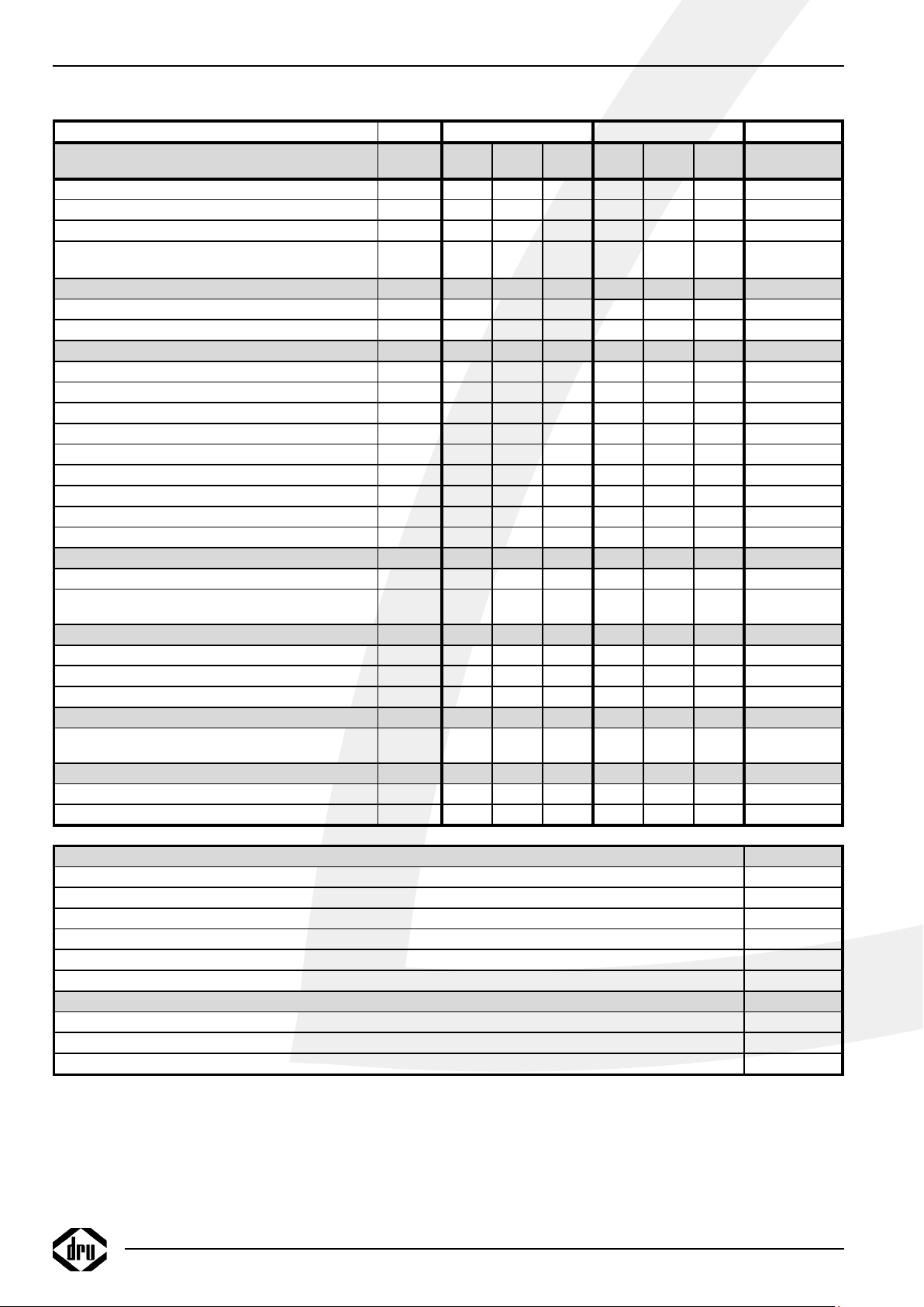
Dru NL 31-01 User guide

INSTALLATIEVOORSCHRIFT EN GEBRUIKERSHANDLEIDING NL/BE
INSTRUCTIONS FOR INSTALLATION AND OPERATION GB/IE
INSTALLATIONSVORSCHRIFT UND GEBRAUCHSANWEISUNG DE/AT/BE/LU/CH
INSTRUCTIONS D’INSTALLATION ET MODE D’EMPLOI FR/BE/LU/CH
NORME PER L’INSTALLAZIONE E INSTRUZIONE PER L’USO IT
MANUAL DE INSTALACIÓN Y GUÍA DEL USUARIO ES
NL 31-01
STYLE 31-01
NL 51-01
Bewaar dit document zorgvuldig
Please retain this document carefully
Bewahren Sie dieses Dokument sorgfältig auf
Conservez soigneusement cette notice
Conservare con cura uesto manuale dell’utente
Guarde cuidadosamente esta guía para el usuario
957.891.00
DRU VERWARMING B.V.
HOLLAND


Nederlands
1
INHOUD
Woord vooraf.......................................................................2
Uitpakken...............................................................................2
Aansluiten...............................................................................2
Installatievoorschrift ............................................................2
Gassoort.................................................................................2
Belangrijk................................................................................2
Algemeen................................................................................2
Installatie aan een wand van onbrandbaar materiaal...2
De standaard geveldoorvoer.............................................2
Installatie van de standaard geveldoorvoer ...................2
De geveldoorvoer met telescopische inlaatpijp............3
Installatie van de geveldoorvoer met
telescopische inlaatpijp........................................................3
Bevestiging van de montageplaat......................................4
Installatie aan een wand van brandbaar materiaal........4
Installatie van het binnenwerk ..........................................4
Aansluiting van de gastoevoer...........................................4
In bedrijf stellen....................................................................5
Kleinstand...............................................................................5
Waakvlambrander................................................................5
Plaatsen van de mantel........................................................5
Gebruikershandleiding ........................................................6
Ontsteken ..............................................................................6
Temperatuur regelen ..........................................................6
Uitschakelen ..........................................................................6
Belangrijk................................................................................6
Eco control pack ..................................................................6
Algemene opmerkingen......................................................7
Onderhoud en reiniging .....................................................7
Verkleuring van wanden en plafonds...............................7
Eerste maal stoken...............................................................7
Extra bescherming ...............................................................7
Afdanken.................................................................................7
Garantie..................................................................................7
Technische gegevens ...........................................................8
INHOUD
NL 31-01 / N 51-01 / STYLE 31-01
CE-VERKLARING
Hierbij verklaren wij dat het door DRU uitgebrachte gasverwarmingstoestel door zijn ontwerp en
bouwwijze voldoet aan de essentiële eisen van de Gastoestellenrichtlijn.
Product: gasverwarmingstoestel
Type: NL-31, NL-51, Style-31
Van toepassing zijnde EG-richtlijnen: 2009/142/EC
Toegepaste geharmoniseerde normen: NEN-EN-613 NEN-EN-613/AI
Door bedrijfsinterne maatregelen is gewaarborgd dat seriematig geproduceerde toestellen aan de
essentiële eisen van de van kracht zijnde EG-richtlijnen en de daarvan afgeleide normen voldoen.
Deze verklaring verliest haar geldigheid als zonder schriftelijke toestemming van DRU wijzigingen aan
het toestel worden aangebracht. U kunt een kopie van het keuringscertificaat downloaden via
www.druservice.com.
Algemeen directeur
Postbus 1021, 6920 BA Duiven
Ratio 8, 6921 RW Duiven
www.dru.nl

Woord vooraf
Geachte klant,
Vriendelijk bedankt voor de aankoop van dit DRU
product. Onze producten zijn ontwikkeld en gefabriceerd
volgens de hoogst mogelijke kwaliteits-, prestatie- en
veiligheidseisen. Hierdoor kunt u rekenen op jarenlang
probleemloos gebruiksplezier.
In dit boekje vindt u instructies voor installatie en gebruik
van uw nieuwe toestel. Lees de instructies en gebruikers-
handleiding goed door, zodat u zich vertrouwd maakt met
het toestel. Wilt u meer ondersteuning, neem dan contact
op met uw leverancier.
Uitpakken
Wanneer u klaar bent met uitpakken, dient de verpakking
via de reguliere weg te worden afgevoerd.
Aansluiten
Dit toestel dient te worden aangesloten door een bevoegd
installateur.
INSTALLATIEVOORSCHRIFT
Gassoort
Dit toestel is bestemd voor het land en geschikt voor de
gassoort dat is vermeld op de typeplaat. Controleer of de
gassoort en de gasdruk ter plaatse overeenkomen met de
vermelding op het typeplaatje. Houdt u aan de gasinstal-
latievoorschriften en eventuele plaatselijke voorschriften.
Het toestel dient door een bevoegd installateur te worden
aangesloten.
Om het toestel te laten werken op butaan of propaan
dient het omgebouwd te worden door een bevoegd instal-
lateur. Een ombouwset is via hem te bestellen.
Belangrijk
• Zorg ervoor dat evt. overgordijnen of andere brandbare
materialen minstens 50 cm van het toestel verwijderd zijn.
• Let op! Aanraking van hete delen kan brandblaren veroor-
zaken!
• Het toestel dient door een erkend installateur
geïnstalleerd te worden.
• Het plaatsen van een z.g. stoffilter op of onder de mantel
is niet toegestaan.
• Natte kleding, handdoeken e.d. niet op de kachel te
drogen hangen!
Algemeen
Het toestel kan zowel aan een wand van onbrandbaar
materiaal (b.v. steen of beton), als aan een wand van
brandbaar materiaal (b.v. hout) geïnstalleerd worden.
Installatie aan een wand van onbrandbaar
materiaal (fig. 1)
Het toestel kan hangend of staand worden geïnstalleerd.
Houd er rekening mee dat boven het toestel minimaal 1
meter vrij ruimte nodig is voor voldoende warmteafvoer.
Als u het toestel zo laag mogelijk wilt installeren moet
de afstand van het hart van de muurdoorvoer tot aan de
vloer maat F zijn.
Voor het aftekenen van de muurdoorvoering kan de mon-
tageplaat (2) als mal worden gebruikt. Om de mantel om
het binnenwerk te kunnen hangen moet men rekening
houden dat tussen een eventuele vensterbank en het toe-
stel een vrije ruimte van minimaal 25 mm noodzakelijk is.
De minimum benodigde vrije installatie hoogte bedraagt
maat Y (tabel 1, blz. 3).
De standaard geveldoorvoer
Maak een horizontaal gat in de muur met een diameter
van ø 230mm (maat E) voor doorvoering van de inlaat-
pijp. Zorg er voor dat de muurdoorvoer ongeveer 2º op
afschot ligt.
De standaard geveldoorvoer is geschikt voor wanddiktes
van 50-330 mm en de standaard verlengde doorvoer voor
wanddiktes van 50-600 mm. Afhankelijk van de wanddikte
dienen de in- en uitlaatpijp op lengte te worden gemaakt n.l.
• lengte inlaatpijp = wanddikte + 20 mm.
• lengte uitlaatpijp = wanddikte + 70 mm.
De aan het muurrooster gemonteerde trekstangen kunnen
na montage van de geveldoorvoer worden ingekort.
Installatie van de standaard geveldoorvoer
(fig. 3)
Schuif de op lengte gemaakte inlaatpijp (1) door de
montageplaat (2) en zorg daarbij dat de felsnaad tegenover
het merkteken (45˚ links boven) in de montageplaat zit.
Schuif de afdichtring (3) en de muurring (4) om de inlaat-
pijp en let daarbij op de volgorde. (zie figuur). Neem het
geheel en schuif de inlaatpijp in de muuropening. De
INSTALLATIE VOORSCHRIFT
2
fig. 3

Nederlands
montageplaat aandrukken tot tegen de wand. De inlaat-
pijp terugdrukken zodanig dat het pijpeinde gelijk ligt met
de omgezette rand van de montageplaat.
Plaats vanaf de buitenzijde het muurrooster met de daar-
aan gemonteerde trekstangen in de inlaatpijp. De trek-
stangen iets naar buiten buigen zodat deze licht klemmen
in de inlaatpijp waardoor het rooster op z’n plaats blijft.
Het merkteken “Top” boven houden bij het plaatsen van
het muurrooster. Schuif de twee bevestigingsbeugels (5)
over de trekstangen (6) en zorg er daarbij voor dat de
bevestigingsbeugels om de omgehaalde rand van de mon-
tageplaat haken. Moeren aanbrengen op de trekstangen
en handvast aandraaien. De bevestigingsbeugels op de
horizontale hartlijn van de inlaatpijp plaatsen. Zie ook de
merktekens in de montageplaat.
De geveldoorvoer met telescopische inlaatpijp
Deze is geschikt voor wanddiktes van 250 - 440 mm
zonder inkorten van de inlaatpijpdelen. Door de pijpdelen
in te korten is deze geveldoorvoer geschikt te maken
voor wanddiktes van 70 tot 250 mm. De uitlaatpijp dient
op lengte te worden gemaakt volgens tabel. De aan het
muurrooster gemonteerde trekstangen kunnen na mon-
tage van de geveldoorvoer worden ingekort.
Indien voor wanddiktes van 70 tot 250 mm de telescopi-
sche inlaatpijp wordt toegepast dienen beide pijpdelen te
worden ingekort n.l.:
• het inlaatpijpdeel aan de muurroosterzijde gelijk aan de
wanddikte
• het pijpdeel aan de toestelzijde op een lengte = de wand-
dikte - 20 mm.
LET OP: de pijpdelen niet afknippen aan de zijde waar
de bevestigingsbeugeltjes zijn aangebracht.
Installatie van de geveldoorvoer met telesco-
pische inlaatpijp (fig. 3)
Breng het muurrooster met de daaraan gemonteerde
inlaatpijphelft van buitenaf in de gemaakte muuropening
met “Top” naar boven bij het plaatsen van het muur-
rooster. Schuif de andere helft van de inlaatpijp door de
montageplaat (2) en zorg daarbij dat de ingelaste beves-
tigingsbeugels (5) op de horizontale hartlijn liggen (zie
de merktekens in de montageplaat) en om de omgezette
montageplaatrand haken.
Breng de afdichtring (3) en de muurring (4) aan om de
inlaatpijp helft (Zie de figuur voor de juiste volgorde).
Neem het geheel en schuif de inlaatpijp helft van bin-
nenuit door de gemaakte muuropening in het reeds
aangebrachte inlaatpijp deel. Zorg daarbij dat de twee
trekstangen (6) door de bevestigingsbeugels (5) steken.
De montageplaat aandrukken tot tegen de wand. Breng
de moeren aan op de trekstangen (6) en zet deze tegen
de bevestigingsbeugels (5) handvast.
INSTALLATIE VOORSCHRIFT
Tabel 1
Type A B D E F K M R S T U Y
NL 31-01 757 339 232 ø 230 167 3/8” 280 Ø210 Ø110 255 79 364
STYLE 31-01 805 390 230 ø 230 192 3/8” 280 Ø210 Ø110 255 79 364
NL51-01 1228 386 289 ø 230 183 3/8” 280 Ø210 Ø110 255 80 401
3
NL 31-01 / N 51-01 / STYLE 31-01
fig. 1
fig. 2

Bevestiging van de montageplaat (fig. 3)
Let op: stel de montageplaat (2) waterpas, zorg ervoor dat
de inlaatpijp naar buiten toe afloopt (1cm op 1 m) en dat
het muurrooster recht tegen de buitenmuur ligt. Eventueel
condenswater zal dan nooit in het toestel kunnen lopen.
• Draai de moeren op de trekstangen vast.
• Zaag of knip de trekstangen af zodat deze niet buiten de
bevestigingsbeugels (5) uitsteken.
• Boor het gat voor de plug / keilmoer (7).
• Breng de plug / keilmoer aan in de muur.
• Bevestig de montageplaat m.b.v. de schroef / bout (8),
incl. sluitring (9).
Installatie aan een wand van brandbaar
materiaal (fig. 2)
Wanneer het toestel aan een wand van brandbaar
materiaal wordt geïnstalleerd dient de wanddoorvoer als
volgt te worden uitgevoerd.
• Maak ter plaatse van de doorvoering een vierkante open-
ing in de wand ( 280mm).
• Bij samendrukbare wanden de ruimte rondom goed opvul-
len zodat de wand niet kan worden ingedrukt.
• De bout / schroef (8) (fig. 3) vervangen door b.v. een
houtdraadbout.
• Plaats aan de kamerzijde tussen de montageplaat (2) en de
wand stralingsplaat 14.
• Bevestig aan de buitenzijde van de wand m.b.v.
4 schroeven (16) siluminplaat 15.
De stralingsplaat 14 en siluminplaat 15 zijn samen verpakt
en te bestellen bij uw leverancier. De montage van de
muurdoorvoer is verder zoals hiervoor beschreven.
N.B. Voor de berekening van de lengte van de in- en uit-
laatpijp dient ook de dikte van siluminplaat 15 te worden
meegeteld.
Installatie van het binnenwerk (fig. 4)
Schuif de op lengte gemaakte uitlaatpijp in de rooster-
opening. Schuif de twee siliconen rubber tulen (verpakt bij
het glaswolkoord) over de bouten (10) en in de gaten van
de achterplaat.
Neem het binnenwerk en zet deze met de onderrand op
de twee steunen van de montageplaat. Houd het binnen-
werk in evenwicht en schuif de uitlaatpijp een klein stukje
in de uitlaatopening van het binnenwerk ter ondersteuning.
Schuif nu het binnenwerk tegen de montageplaat en zorg
er daarbij voor dat de omgezette montageplaatrand in de
inlaatbus op de achterzijde van het binnenwerk valt en de
bouten (10) door de beugels (11) steken. Moeren en sluit-
ringen op de bouten (10) aanbrengen en vast aandraaien
tot tegen de aanslag. Daarna de draadstang (12) in de
beugel (13) schuiven. Moer met sluitring op de draadstang
(12) aanbrengen en aandraaien tot het binnenwerk parallel
met de wand staat.
N.B. Wanneer gemakkelijk toegankelijk, b.v. op de begane
grond, kan de uitlaatpijp ook van buitenaf worden aange-
bracht nadat de roosterbinnenplaat en de korf zijn gede-
monteerd.
Aansluiting van de gastoevoer
De aansluiting is 3/8” BSP binnendraad. Indien de toevoer-
leiding door de achterplaat het toestel binnenkomt moet
men het plaatje uitdrukken. Gebruik in de toevoerleiding
een gekeurde aansluitkraan met koppeling (voor Belgie
moet deze B.G.V. gekeurd zijn). De aansluitkraan met kop-
peling dient buiten de mantel te worden geplaatst. Verder
geldt:
• Ontlucht de toevoerleiding voordat het toestel wordt
vastgekoppeld.
• De bedieningskraan mag niet verdraaid worden bij het
aansluiten aan de gastoevoerleiding.
• Vermijd spanningen op de bedieningskraan en leidingen.
• Controleer de aansluitingen op gasdichtheid.
4
INSTALLATIE VOORSCHRIFT
fig. 4

In bedrijf stellen
Het toestel is door de fabriek ingericht voor de gassoort
zoals op het typeplaatje is aangegeven.
De thermostaat regelt modulerend tussen ,volstand” en
,kleinstand” en bij een geringe warmtebehoefte in twee
posities, n.l. ,kleinstand” of ,uit”. Hierbij blijft de waakvlam
steeds branden. De kleinstand kan alleen worden gecon-
troleerd wanneer de kamertemperatuur hoger is dan ca.
15° C (60° F).
Kleinstand
De kleinstand is ingesteld op ± 20 % van het volverbruik.
De kleinstandschroef is geheel ingedraaid en voorzien van
de juiste kleinstandboring. Deze is niet instelbaar.
Waakvlambrander
De waakvlambrander heeft bij levering het juiste verbruik
d.m.v. een spuitstuk dat zich in de waakvlambrander bevindt.
De waakvlambrander behoeft niet te worden ingesteld.
Plaatsen van de mantel
Hang de mantel aan de bovenzijde over de achterplaat
(zijkanten van de mantel blijven voor de achterplaat) en
zorg daarbij dat de bedieningsknoppen in de daarvoor
bestemde mantelopening vallen.
Nederlands
INSTALLATIE VOORSCHRIFT
5
NL 31-01 / N 51-01 / STYLE 31-01

GEBRUIKERSHANDLEIDING
6
GEBRUIKERSHANDLEIDING
Ontsteken
De ontsteekknop A heeft drie standen namelijk:
O stand knop wijst naar O
Waakvlamstand knop wijst naar
Vol stand knop wijst naar
Draai de Ontsteekknop vanaf O stand linksom, tevens
goed indrukken en doordraaien naar de waakvlamstand .
Door het draaien aan de knop wordt de waakvlambrander
door een elektrische vonk ontstoken. Als de waakvlam
brandt, de knop nog ca 10 sec. ingedrukt houden en dan
loslaten. De waakvlambrander is zichtbaar aan de zijkant
achter het glasraam. Als de waakvlam niet in één keer
ontsteekt, kan bovenstaande handeling meteen herhaald
worden door met ingedrukte knop terug te draaien rich-
ting O en weer linksom richting waakvlamstand. Na het
loslaten van de ansteekknop moet de waakvlam blijven
branden. De aansteekknop vervolgens verder draaien naar
volstand . Afhankelijk van thermostaatknop B zal de
hoofdbrander ontstoken worden.
Temperatuur regelen
De stand van de thermostaatknop B bepaalt de tempera-
tuur in de kamer. Stand 6 geeft de hoogste temperatuur
en stand 1 de laagste. De thermostaat regelt modulerend
tussen “volstand” en “kleinstand” van de brander. De
thermostaat houdt de kamer automatisch op de gewenste
ingestelde temperatuur.
Uitschakelen
Draai de ontsteekknop A terug naar de Waakvlamstand
(symbool ), alleen de waakvlam blijft branden. Om het
toestel volledig uit te zetten drukt u vervolgens knop A in
en draait hem terug naar stand O.
Belangrijk
Een ingebouwde veiligheidsvergrendeling treedt in werking
wanneer het toestel op ,,UIT” (stand O) wordt gezet.
Wacht daarom 5 minuten alvorens het toestel opnieuw
te ontsteken. Probeer binnen deze tijd niet de aansteek-
knop in te drukken, daar deze door de veiligheidsvergren-
deling geblokkeerd is. Forceer de knop niet, omdat het
mechanisme dan kan worden beschadigd.
Eco control pack
Voor dit toestel is een los verkrijgbare “Eco control pack”
met afstandsbediening beschikbaar. Het “Eco control pack”
is nodig om het optimale uit uw toestel te halen.
Bij deze set zit een ontvanger, plaats deze in het daarvoor
bestemde bakje.
Het bakje bevindt zich Onder het gasregelblok.
Voorkom dat de kabels tegen de hete delen van het bin-
nenwerk aankomen.
GEBRUIKERSHANDLEIDING
Ontsteken
DeontsteekknopAheeftdriestandennamelijk:
Ostand knopwijstnaarO
Waakvlamstand knopwijstnaar
Volstand knopwijstnaar
DraaideOntsteekknopvanafOstandlinksom,
tevensgoedindrukkenendoordraaiennaarde
waakvlamstand.Doorhetdraaienaandeknop
wordtdewaakvlambranderdooreenelektrische
vonkontstoken.Alsdewaakvlambrandt,deknop
nogca10sec.ingedrukthoudenendanloslaten.
Dewaakvlambranderiszichtbaaraandezijkant
achterhetglasraam.Alsdewaakvlamnietinéén
keerontsteekt,kanbovenstaandehandeling
meteenherhaaldwordendoormetingedrukte
knopterugtedraaienrichtingOenweerlinksom
richtingwaakvlamstand.Nahetloslatenvande
ansteekknopmoetdewaakvlamblijvenbranden.
Deaansteekknopvervolgensverderdraaiennaar
volstand.AfhankelijkvanthermostaatknopBzal
dehoofdbranderontstokenworden.
Temperatuurregelen
DestandvandethermostaatknopBbepaaltde
temperatuurindekamer.Stand6geeftdehoogste
temperatuurenstand1delaagste.Dethermostaat
regeltmodulerendtussen“volstand”en
“kleinstand”vandebrander.Dethermostaat
houdtdekamerautomatischopdegewenste
ingesteldetemperatuur.
Uitschakelen
DraaideontsteekknopAterugnaarde
Waakvlamstand(symbool),alleendewaakvlam
blijftbranden.Omhettoestelvollediguittezetten
druktuvervolgensknopAinendraaithemterug
naarstandO.
Belangrijk
Eeningebouwdeveiligheidsvergrendelingtreedtin
werkingwanneerhettoestelop,,UIT”(standO)
wordtgezet.Wachtdaarom5minutenalvorens
hettoestelopnieuwteontsteken.Probeerbinnen
dezetijdnietdeaansteekknopintedrukken,daar
dezedoordeveiligheidsvergrendelinggeblokkeerd
is.Forceerdeknopniet,omdathetmechanisme
dankanwordenbeschadigd.
Ecocontrolpack
Voordittoesteliseenlosverkrijgbare“Ecocontrol
pack”metafstandsbedieningbeschikbaar.Het
“Ecocontrolpack”isnodigomhetoptimaleuituw
toesteltehalen.
Bijdezesetziteenontvanger,plaatsdezeinhet
daarvoorbestemdebakje.
HetbakjebevindtzichOnderhetgasregelblok.
Voorkomdatdekabelstegendehetedelenvan
hetbinnenwerkaankomen.
1
6
2
3
4
5
A
B
38P-0744/0

Nederlands
ALGEMENE OPMERKINGEN
Onderhoud en reiniging
Uw toestel dient eenmaal per jaar door een gekwalificeerd
bedrijf te worden gecontroleerd, en waar nodig, hersteld
of gereinigd. De controle en het onderhoud dient in ieder
geval een goede en veilige werking van het toestel te
omvatten. U kunt hiervoor gebruik maken van uw gasin-
stallateur of een gespecialiseerd onderhoudsbedrijf. Het
verdient aanbeveling om vóór en tijdens het stookseizoen
het toestel enkele malen stofvrij te maken. Bij het reini-
gen van de mantel geen bijtende of schurende middelen
gebruiken. Lakbeschadigingen, bijvoorbeeld door het plaat-
sen van voorwerpen op of tegen de mantel, vallen buiten
de garantie.
Let op: Bij het vervangen van het thermokoppel moet
de wartel in het gasregelblok handvast gedraaid worden,
waarna deze met een steeksleutel een kwartslag aange-
draaid moet worden.
Verkleuring van wanden en plafonds
Bruinverkleuring is een vervelend probleem en is moeilijk
op te lossen. Bruinverkleuring kan worden veroorzaakt
door onder andere stofverbranding veroorzaakt door te
weinig ventilatie, door het roken van sigaretten of het
branden van kaarsen.
Deze problemen kunnen worden voorkomen door:
Het vertrek waar het toestel zich bevind goed te ventile-
ren. Een goede richtlijn hiervoor is (vlg. het Nederlands
Bouwbesluit):
Bij nieuwbouw : 3.24 m3/ uur per m2
vloeroppervlak van een vertrek.
Bij bestaande bouw : 25.20 m2/ uur voor een vertrek.
Maak zo weinig mogelijk gebruik van kaarsen en olielamp-
jes en houd het verbrandingslontje zo kort mogelijk. Deze
“sfeerbrengers” zorgen voor aanzienlijke hoeveelheden
vervuilde en ongezonde roetdeeltjes in uw woning. Rook
van sigaretten en sigaren bevat o.a. teerstoffen die bij
verhitting eveneens op koudere en vochtige muren zullen
neerslaan. Bij een nieuw gemetselde schouw of na een ver-
bouwing wordt aanbevolen minimaal 6 weken te wachten
voordat men gaat stoken, het bouwvocht moet namelijk
geheel verdwenen zijn uit wanden, vloer en plafond.
Eerste maal stoken
Tijdens de eerste maal stoken kan er een onaangename
geur ontstaan, die wordt veroorzaakt door het uitdampen
van de lak. Dit verdwijnt na enkele uren. Daarom raden
wij u aan het toestel de eerste maal op de hoogste stand
te stoken terwijl u tevens het vertrek waarin de kachel
staat goed ventileert.
Extra bescherming
Indien het toestel in een vertrek geïnstalleerd wordt waar
jonge kinderen of hulpbehoevende mensen zonder toe-
zicht verblijven, is het wenselijk het toestel af te schermen.
Afdanken
Indien u het toestel vervangt of verwijdert, moet u het
toestel via de reguliere weg afvoeren. Voordat tot demon-
tage wordt overgegaan eerst de aansluitkraan met kop-
peling dichtdraaien. De koppeling tussen aansluitkraan
en toestel losdraaien. Het gehele toestel kan nu worden
gedemonteerd en afgevoerd.
Garantie
De garantie op uw DRU toestel wordt verleend via uw
leverancier. In geval van storingen dient u altijd met hem
contact op te nemen. Uw leverancier zal DRU inschakelen
indien hij dit noodzakelijk acht. De fabrieksgarantie op uw
toestel bedraagt 2 jaar na datum van aankoop.
ALGEMENE OPMERKINGEN
7
NL 31-01 / N 51-01 / STYLE 31-01

TECHNISCHE GEGEVENS
8
Typeaanduiding(en):
Gassoort: Symbool G25/
G25.3* G20 G31 G25/
G25.3* G20 G31 Eenheid
Indirecteverwarmingsfunctionaliteit Nee Nee Nee Nee Nee Nee
Directewarmteafgifte 2,8 2,9 2,9 5,6 5,9 6,0 kW
Indirectewarmteafgifte ‐‐‐‐‐‐ kW
UitstootbijruimteverwarmingNox88,8 106,4 102,6 63,7 76,0 89,5 mg/kWhinput
(GCV)
Warmteafgifte
Nominalewarmteafgifte Pnom 2,8 2,9 2,9 5,6 5,9 6,0 kW
Minimalewarmteafgifte(indicatief) Pmin 0,8 0,8 1,0 1,4 1,5 1,9 kW
Technischegegevens
Nominalebelasting(Hs) 3,5 3,6 3,5 7,0 7,3 7,3 kW
Nominalebelasting(Hi) 3,2 3,2 3,2 6,3 6,6 6,7 kW
Gasverbruikvolstand 372 339 130 752 683 272 l/h
Gasverbruikkleinstand 103 94 43 196 184 90 l/h
Branderdrukvolstand 17,4 13,9 25,1 12,5 9,9 17,4 mbar
Branderdrukkleinstand 0,9 0,8 2,1 0,7 0,6 1,6 mbar
Branderspuitstuk 1,45 1,45 1,00 2,25 2,25 1,55 mm
Kleinstelspuitstuk 0,65 0,65 0,50 1,00 1,00 0,80 mm
Rendementsklasse(EN613) 111111
Nuttigrendement(NCV)
Nuttigrendementbijnominalewarmteafgifteηth,nom 88,8 89,2 89,6 88,7 89,1 89,5 %
Nuttigrendementbijminimalewarmteafgifte
(indicatief)ηth,min 87,9 87,8 86,9 87,0 86,8 86,9 %
Aanvullendelektriciteitsverbruik
Bijnominalewarmteafgifteelmax ‐‐‐‐‐‐ kW
Bijminimalewarmteafgifte elmin ‐‐‐‐‐‐ kW
Instand‐bymodus elSB ‐‐‐‐‐‐ kW
Vermogenseisvoordepermanentewaakvlam
Vermogenseisvoordepermanentewaakvlam(indien
vantoepassin
g
)Ppilot ‐‐‐‐‐‐ kW
Energie‐efficiëntie
Energie‐efficiëntie‐index EEI 89 89 90 89 89 90
Energie‐efficiëntieklasseAAAAAA
Nee
Nee
Ja
Ja**
Ja**
Ja**
Ja**
Ja**
Ja**
**DezefunctieszijnalleenvantoepassingincombinatiemethetlosverkrijgbareEcocontrolpack.
Tweeofmeerhandmatigintestellentrappen,geensturingvandekamertemperatuur
Metelektronischesturingvandekamertemperatuurplusdag‐tijdschakelaar
Metelektronischesturingvandekamertemperatuurplusweek‐tijdschakelaar
Anderesturingsopties
Metdeoptievanafstandsbediening
Sturingvandekamertemperatuur,metaanwezigheidsdetec�e
Sturingvandekamertemperatuur,metopenraamdetec�e
Metmechanischesturingvandekamertemperatuurdoorthermostaat
Metelektronischesturingvandekamertemperatuur
NL‐31‐01/Style31‐01 NL‐51
Eentrapswarmteafgifte,geensturingvandekamertemperatuur
Typewarmteafgifte/sturingkamertemperatuur
*DittoestelisgeschiktvoorG25.3metdesamenstellingvolgensNTA8837.

CONTENTS
CONTENTS
Foreword .............................................................................10
Unpacking.............................................................................10
Connection..........................................................................10
Instructions for installation..............................................10
Type of gas...........................................................................10
Important .............................................................................10
General.................................................................................10
Installing the heater against a wall of
incombustible material......................................................10
The standard wall duct .....................................................10
Installation of the standard exterior wall duct ...........10
The exterior wall duct with telescopic inlet pipe......11
Installation of the wall duct with
telescopic inlet pipe...........................................................11
Fastening the mounting sheet .........................................12
Installation to a wall of inflammable material..............12
Connection of the gas supply ........................................12
Operations...........................................................................13
The low setting...................................................................13
Pilot light burner ................................................................13
Placing the housing.............................................................13
User Manual.........................................................................14
Ignition ..................................................................................14
Controlling the temperature...........................................14
Switching off ........................................................................14
Important .............................................................................14
Eco control pack ................................................................14
General notes .....................................................................15
Gas safety regulations (for installation & use), 1998.15
Cleaning and Maintenance................................................15
Discoloration of walls and ceiling ..................................15
Lighting the heater for the first time.............................15
Extra protection.................................................................15
Disposal ................................................................................15
Guarantee ............................................................................15
Technical data .....................................................................16
English
9
NL 31-01 / N 51-01 / STYLE 31-01
CE-DECLARATION
We hereby declare that the design and construction of DRU’s gas-fired heating appliance comply with
theessential requirements of the Gas Appliance Directive.
Product: gas-fired heating appliance
Type: NL-31, NL-51, Style-31
EEC directives: 2009/142/EC
Standards: NEN-EN-613 NEN-EN-613/AI
Internal precautions at the company will guarantee that appliances produced in series comply with the
essential requirements of the EC directives in force and the standards derived from them.
This declaration will lose its validity if adjustments are made to the appliance without prior written
permission by DRU.A copy of the test certificate can be downloaded via www.druservice.com.
General manager
Postbus 1021, 6920 BA Duiven
Ratio 8, 6921 RW Duiven
www.dru.nl

Foreword
Dear Customer,
We would like to thank you for buying this DRU prod-
uct. Our products have been designed and produced to
meet the highest possible quality, performance and safety
requirements, allowing you to enjoy years of problem-free
use.
In this booklet you will find instructions for the installation
and use of your new appliance. Please read these instruc-
tions and the manual carefully to familiarize yourself with
the appliance. If you require any further support, please do
not hesitate to contact your supplier.
Unpacking
Once the heater has been unpacked, all packaging should
be disposed of in the regular manner.
Connection
This appliance should be connected by a registered
installer.
INSTRUCTIONS FOR INSTALLATION
Type of gas
This appliance can only be used and is only suitable for the
country and the type of gas mentioned on the type iden-
tification tag. Please check that the local gas and pressure
correspond with the specifications on the type identifica-
tion tag. All regulations regarding gas installation, including
any local regulations, must be observed at all times. The
appliance is to be installed by a registered installer.
To operate the heater on bultane or propane, it should be
converted by a registered installer. A conversion set can
be ordered through him.
Important
• Keep curtains and any other flammable materials at least
50cm away form the appliance.
• Caution! Touching the heater when hot can cause burns
and blisters!
• The appliance should be installed and maintained by a
registered installer.
• Do not install any so-called dust filter on or under the
casing.
• Do not hang wet clothes and towels etc. on the heater to
dry.
General
The appliance can be mounted either on a wall of incom-
bustible material (e.g. stone or concrete) or on a wall of
combustible material (e.g. wood).
Installing the heater against a wall of
incombustible material (fig. 1)
The appliance can be installed in a hanging or standing
position. Allow at least 1 metre’s clearance above the
heater to enable sufficient heat circulation. If you want to
install the appliance as low as possible, the distance from
the centre of the wall duct to the floor should be dimen-
sion F (table 1, page 9).
The mounting plate (2) serves as a stencil to mark the
position of the duct. To be able to hang the casing over
the interior, a minimal clearance of 25 mm must be allo-
wed between the appliance and a windowsill or suchlike.
The minimum total free height for installation is dimension
Y (table 1, page 9).
The standard wall duct
Drill a horizontal hole in the wall, ø 230mm (E) in diam-
eter, to take the air-supply pipe. The wall duct should
slope at an angle of approx. 2º.
The standard wall duct is suitable for walls with a thick-
ness of 50 – 330 mm and the standard extended wall duct
for walls with a thickness of 50 – 600 mm. Depending on
the thickness of the wall, the inlet and outlet pipes should
be made to length, i.e.:
• length inlet pipe = wall thickness + 20 mm.
• length outlet pipe = wall thickness + 70 mm.
The tension members fixed to the wall grid can be made
to size after installation
Installation of the standard exterior wall duct
(fig. 3)
Slide the adjusted inlet pipe (1) through the mounting
sheet (2), with the turned-back edge facing the mark (45º
top left) in the mounting sheet. Slide the sealing ring (3)
and the wall ring (4) around the inlet pipe, paying atten-
tion to the order (see figure). Take the whole and slide
the inlet pipe into the wall opening. Press the mounting
10
INSTRUCTIONS FOR INSTALLATION
fig. 3

English
INSTRUCTIONS FOR INSTALLATION
sheet up to the wall. Press the inlet pipe back in such a
way that the end of the pipe is level with the turned-back
edge of the mounting sheet.
From the outside, bring the wall grid with its attached
tension members into the inlet pipe. Bend the tension
members a little outwards, so that they will jam slightly
in the inlet pipe, keeping the grid in its place. Keep the
mark “Top” up when placing the wall grid. Slide the two
fastening clamps (5) over the tension members (6), taking
care that the fastening clamps catch on the turned-back
edge of the mounting sheet. Fix the screw-nuts onto the
tension members and tighten them by hand. Place the fas-
tening clamps onto the horizontal centre line of the inlet
pipe. See also the marks in the mounting sheet.
The exterior wall duct with telescopic inlet
pipe
This is suitable for wall thicknesses of 250 – 440 mm
without shortening the parts of the inlet pipe. By short-
ening the pipe’s parts, this exterior wall duct can be
adapted for thicknesses of 70 – 250 mm. The outlet pipe
should be adjusted. The tension members attached to
the wall grid can be shortened after the wall duct has
been mounted. If the telescopic inlet pipe is applied for
wall thicknesses of 70 – 250 mm, both parts of the pipe
should be shortened, i.e.:
• the part of the inlet pipe on the side of the wall grid
equal to the thickness of the wall
• the part of the pipe on the side of the heater to a length
equalling the wall thickness minus 20 mm.
CAUTION: do not cut the pipe parts on the side
where the fastening clamps have been applied.
Installation of the wall duct with telescopic
inlet pipe (fig. 3)
From the outside, put the wall grid, together with the
attached half inlet pipe into the created wall opening,
keeping “Top” up when placing the wall grid. Slide the
other half of the inlet pipe through the mounting sheet
(2), making sure that the inserted fastening clamps (5)
lie on the horizontal centre line (see the marks in the
mounting sheet). They should catch on the turned-back
edge of the mounting sheet.
Attach the sealing ring (3) and the wall ring (4) to the
half inlet pipe (see ffigure for the correct order). Take
the whole and, from the inside, slide the half inlet pipe
through the created wall opening into the part of the
inlet pipe already mounted. While doing so, make sure
the the two tension members (6) stick through the fas-
tening clamps. Press the mounting sheet up to the wall.
Appply the screw-nuts onto the tension members (6) and
tighten them by hand against the fastening clamps (5).
Table 1
Type A B D E F K M R S T U Y
NL 31-01 757 339 232 ø 230 167 3/8” 280 Ø210 Ø110 255 79 364
STYLE 31-01 805 390 230 ø 230 192 3/8” 280 Ø210 Ø110 255 79 364
NL 51-01 1228 386 289 ø 230 183 3/8” 280 Ø210 Ø110 255 80 401
11
NL 31-01 / N 51-01 / STYLE 31-01
fig. 1
fig. 2

Fastening the mounting sheet (fig. 3)
Caution: Level the mounting sheet, make sure that the
inlet pipe goes down towards the outside. (1 cm to 1 m)
and that the wall grid lies straight against the exterior wall.
Then, any condensation will never get into the heater
because of the downwards flow of the pipe.
• Now tighten the screw nuts on the tension members
• Saw or cut the tension members so that they do not stick
out from the fastening clamps (5).
• Drill the hole for the key bolt (7).
• Attach the key bolt and attach the mounting sheet using
the bolt (8) and washer (9).
Installation to a wall of inflammable material
(fig. 2)
When the appliance is installed to a wall of flammable
material, the wall duct should be executed as follows.
• On the spot of the duct, create a square opening in the
wall ( 280 mm).
• In the case of compressible walls, fill up the space all
round the opening well, so that the wall cannot be
crushed.
• In addition, replace the bolt (8) (fig 3) by e.g. a wood
screwed bolt.
• On the room side, put the heat shield (14) between the
mounting sheet (2) and the wall.
• On the outside of the wall, using 4 screws (16), attach
siluminplate (15).
The heat shield (14) and the silumin plate (15) are packed
together and are available from your dealer. Assembling
the wall duct is otherwise the same as previously
described.
N.B. To calculate the length of the inlet and outlet pipe,
the thickness of siluminplate (15) should be included.
Installation of the interior (fig.4)
Slide the adjusted outlet pipe into the gird opening. Slide
the two Silicon Rubber Tulles (packed with the glass silk
rope) over the bolts (10) and into the holes of the back
plate.
This prevents possible dirt and deposit from settling onto
the wall. Take the interior and put it with the bottom
edge on the two supports of the mounting sheet. Keep
the interior balanced and slide the outlet pipe a little bit
into the outlet opening of the interior for support. Now
slide the interior against the mounting sheet, taking care
that the turned-back edge of the mounting sheet fits into
the inlet bush on the back side of the interior and that
the bolts (10) stick through the clamps (11). Attach screw
nuts and washers to the bolts (10) and tighten closely up
to the stop. Then slide the screw spindle (12) into the
clamp (13). Fix the screw nut and washer to the screw
spindle (12) and tighten until the interior is standing paral-
lel to the wall.
N.B. If easy accessible, e.g. on the ground floor, the outlet
pipe can also be mounted from the outside after the grid
interior sheet and the basket have been disassembled.
Connection of the gas supply
The connection has a 3/8” BSP inside thread. If the supply
pipe enters the appliance through the back plate, press out
the disc in the plate. An approved connecting tap with
coupling should be used in the supply pipe (For Belgium
this should be B.G.V. approved). The connecting tap with
coupling should be fitted outside the casing. Furthermore:
• Expel all air from the supply pipes/hoses before coupling
to the appliance.
• Do not turn the coupling tap when connecting it to the
gas supply.
• Avoid any pressure on the control tap and pipes.
• Check that all connections are gastight.
12
INSTRUCTIONS FOR INSTALLATION
fig. 4

Operations
The manufacturer has made the appliance suitable for the
type of gas as indicated on the type identification tag. The
thermostat regulates modulatingly between “full power
setting” and “low power setting” and , when little heat is
required, in two settings, i.e. “low” or “off”. In this situa-
tion, the pilot light keeps burning. The “low” setting can
only be checked when the room temperature is higher
than ± 15°C (60°F).
The low setting
The low setting has been adjusted to ± 20% of the full
consumption. The low setting screw has been fully tight-
ened and is supplied with the correct low setting bore.
This is not adjustable.
Pilot light burner
Upon delivery, the pilot light burner has the correct con-
sumption by means of a nozzle inside the pilot light burn-
er. The pilot light burner needs no adjustment.
Placing the housing
Hang the top of the casing over the back plate (the sides
of the casing remain in front of the back plate) and ensure
that the control buttons drop into the appropriate recess
in the casing.
English
INSTRUCTIONS FOR INSTALLATION
13
NL 31-01 / N 51-01 / STYLE 31-01

USER MANUAL
14
USER MANUAL
Ignition
Ignition button A has three positions, i.e.:
O position button points to O
Pilot burner position button points to
Full position button points to
Turn the ignition button to the left from position O, press
down firmly as well and keep turning to the pilot burner
position . By turning the button, the pilot burner is
ignited by means of an electrical spark. When the pilot
burner burns, keep pressing down the button for approx.
10 sec. and then let go. The pilot burner is visible from
the side, behind the glass window. If the pilot burner does
not ignite at once, the above-mentioned action can be
repeated immediately by turning the pressed down but-
ton back towards O and then left again towards the pilot
burner position. After letting go of the ignition button, the
pilot burner should continue to burn. Then turn the
ignition button further towards the full position .
Depending on thermostat button B, the main burner will
be ignited.
Controlling the temperature
The position of thermostat button B determines the
temperature in the room. Position 6 provides the highest
temperature, position 1 the lowest. The thermostat
controls the burner by modulating between “full position”
and “low position” of the burner. The thermostat will
automatically keep the room at the required set
temperature.
Switching off
Turn ignition button A back to the Pilot Burner position
( symbol), only the pilot burner will continue to burn.
In order to switch off the appliance fully, you must press
down button A and turn it back to position O.
Important
An incorporated safety lock will be activated if the appli-
ance is set to the ,,OFF” (O) position. Therefore, wait 5
minutes before re-igniting the appliance. Do not try to
press down the ignition button during this time, as it is
locked by means of the safety lock. Do not force the but-
ton, because the mechanism could get damaged.
Eco control pack
It is possible to order a separately available “Eco control
pack” with remote control. The “Eco control pack” is
needed to get the best out of your appliance.
This set has a receiver that must be placed in the tray spe-
cifically intended for this purpose.
The tray is located under the gas control.
Prevent cables from making contact with hot internal
components.
GEBRUIKERSHANDLEIDING
Ontsteken
DeontsteekknopAheeftdriestandennamelijk:
Ostand knopwijstnaarO
Waakvlamstand knopwijstnaar
Volstand knopwijstnaar
DraaideOntsteekknopvanafOstandlinksom,
tevensgoedindrukkenendoordraaiennaarde
waakvlamstand.Doorhetdraaienaandeknop
wordtdewaakvlambranderdooreenelektrische
vonkontstoken.Alsdewaakvlambrandt,deknop
nogca10sec.ingedrukthoudenendanloslaten.
Dewaakvlambranderiszichtbaaraandezijkant
achterhetglasraam.Alsdewaakvlamnietinéén
keerontsteekt,kanbovenstaandehandeling
meteenherhaaldwordendoormetingedrukte
knopterugtedraaienrichtingOenweerlinksom
richtingwaakvlamstand.Nahetloslatenvande
ansteekknopmoetdewaakvlamblijvenbranden.
Deaansteekknopvervolgensverderdraaiennaar
volstand.AfhankelijkvanthermostaatknopBzal
dehoofdbranderontstokenworden.
Temperatuurregelen
DestandvandethermostaatknopBbepaaltde
temperatuurindekamer.Stand6geeftdehoogste
temperatuurenstand1delaagste.Dethermostaat
regeltmodulerendtussen“volstand”en
“kleinstand”vandebrander.Dethermostaat
houdtdekamerautomatischopdegewenste
ingesteldetemperatuur.
Uitschakelen
DraaideontsteekknopAterugnaarde
Waakvlamstand(symbool),alleendewaakvlam
blijftbranden.Omhettoestelvollediguittezetten
druktuvervolgensknopAinendraaithemterug
naarstandO.
Belangrijk
Eeningebouwdeveiligheidsvergrendelingtreedtin
werkingwanneerhettoestelop,,UIT”(standO)
wordtgezet.Wachtdaarom5minutenalvorens
hettoestelopnieuwteontsteken.Probeerbinnen
dezetijdnietdeaansteekknopintedrukken,daar
dezedoordeveiligheidsvergrendelinggeblokkeerd
is.Forceerdeknopniet,omdathetmechanisme
dankanwordenbeschadigd.
Ecocontrolpack
Voordittoesteliseenlosverkrijgbare“Ecocontrol
pack”metafstandsbedieningbeschikbaar.Het
“Ecocontrolpack”isnodigomhetoptimaleuituw
toesteltehalen.
Bijdezesetziteenontvanger,plaatsdezeinhet
daarvoorbestemdebakje.
HetbakjebevindtzichOnderhetgasregelblok.
Voorkomdatdekabelstegendehetedelenvan
hetbinnenwerkaankomen.
1
6
2
3
4
5
A
B
38P-0744/0

English
GENERAL NOTES
Gas Safety Regulations (for installation & use) 1998
In your own interest and that of safety, it is law that
all gas appliances are installed by competent persons in
accordance with the above regulations. Failure to install
appliances correctly could lead to prosecution.
NB: The Confederation of Registered Gas
Installers, whose members are identified by the
emblem shown here, are all required to work to
the recognised standards.
Cleaning and Maintenance
The appliance should be inspected once a year by a
qualified company, and cleaned and/or repaired as neces-
sary.The inspection and maintenance must at least ensure
that the appliance is working correctly and safely.This
can be done by your own gasinstaller or a specialised
maintenance company. You are recommended to free the
heater of dust before and occasionally during the heating
season.Do not use abrasives when cleaning the heater.
Damage to the casing varnish, caused by anything being
put on the appliance, is not covered by the guarantee.
NB: When replacing the pilot light burner, the coupling
nut in the gas control block should first be tightened by
hand and then tightened a quarter-turn with an
open-ended spanner.
Discoloration of walls and ceiling
Brown discoloration is an annoying problem, which is
difficult to solve. It can be caused by dust burning as a
result of poor ventilation, for example, or by cigarette
smoke or candles.
These problems can be avoided by ensuring that the
room the heater is in is properly ventilated. A good
guideline for ventilation is:
New buildings : 3.24 m3/ hour per m2floor
surface of the room.
Existing buildings : 25.20 m2/ hour for a room.
Use candles and oil lamps as little as possible, keeping the
wick as short as possible. While they enhance the atmo-
sphere, candles and oil lamps also cause the formation of
large quantities of unhealthy soot particles in your home.
Cigarette and cigar smoke contains tar, which upon heat-
ing will precipitate on cold or damp walls. If you have a
newly cemented chimney or have had any other recon-
structions / renovations done, you are advised to wait at
least 6 weeks before lighting your fire, to allow the walls,
floor and ceiling to dry out completely.
Lighting the heater for the first time
There can be an unpleasant smell when you light the
heater for the first time. This is caused by the varnish
evaporating and will disappear after a few hours. We
therefore advise you, on initial use, to heat the appli-
ance at the highest setting while ventilating the room it is
installed in well.
Extra protection
This heater meets the normal safety standards regarding
surface temperatures, but physical contact with heated
surfaces should be avoided where possible. An additional
guard is recommended to protect young children and
elderly, infirmed or handicapped people.
Disposal
When replacing or otherwise removing the appliance, it
should be disposed of in compliance with current regula-
tions.
Shut off the connecting tap with coupling before com-
mencing disassembly. Undo the coupling between the
connecting tap and the appliance. The whole appliance
can now be disassembled and removed.
Guarantee
The warranty for your DRU appliance will be provided by
your supplier. In case of malfunctions, you should always
contact him. You supplier will contact DRU if he feels this
is necessary. The factory warranty for your appliance is
valid for 2 years after date of purchase.
GENERAL NOTES
15
NL 31-01 / N 51-01 / STYLE 31-01

16
Modelidentifier(s):
Gastype: Symbol G25/
G25.3* G20 G31 G25/
G25.3* G20 G31 Unit
Indirectheatingfunctionality No No No No No No
Directheatoutput 2,8 2,9 2,9 5,6 5,9 6,0 kW
Indirectheatoutput ‐‐‐‐‐‐ kW
SpaceheatingemissionsNOx88,8 106,4 102,6 63,7 76,0 89,5 mg/kWhinput
(GCV)
Heatoutput
Nominalheatoutput Pnom 2,8 2,9 2,9 5,6 5,9 6,0 kW
Minimumheatoutput(indicative) Pmin 0,8 0,8 1,0 1,4 1,5 1,9 kW
Technicaldata
Nominalheatinput(Hs) 3,5 3,6 3,5 7,0 7,3 7,3 kW
Nominalheatinput(Hi) 3,2 3,2 3,2 6,3 6,6 6,7 kW
Consumptionmax 372 339 130 752 683 272 l/h
Consumptionmin 103 94 43 196 184 90 l/h
Burnerpressuremax 17,4 13,9 25,1 12,5 9,9 17,4 mbar
Burnerpressuremin 0,9 0,8 2,1 0,7 0,6 1,6 mbar
Mainburnerinjector 1,45 1,45 1,00 2,25 2,25 1,55 mm
Lowsettinginjector 0,65 0,65 0,50 1,00 1,00 0,80 mm
Efficiencyclass(EN613) 111111
Usefulefficiency(NCV)
Usefulefficiencyatnominalheatoutput ηth,nom 88,8 89,2 89,6 88,7 89,1 89,5 %
Usefulefficiencyatminimumheatoutput(indicative) ηth,min 87,9 87,8 86,9 87,0 86,8 86,9 %
Auxiliaryelectricityconsumption
Atnominalheatoutput elmax ‐‐‐‐‐‐ kW
Atnominalheatoutput elmin ‐‐‐‐‐‐ kW
Instandbymode elSB ‐‐‐‐‐‐ kW
Permanentpilotflamepowerrequirement
Pilotflamepowerrequirement(ifapplicable) Ppilot ‐‐‐‐‐‐ kW
Energyefficiency
Energyefficiencyindex EEI 89 89 90 89 89 90
Energyefficiencyclass AAAAAA
No
No
Yes
Yes**
Yes**
Yes**
Yes**
Yes**
Yes**
Withmechanicthermostatroomtemperaturecontrol
*ThisapplianceissuitableforG25.3withthecompositionaccordingNTA8837.
**Thesefunctionsonlyapplyincombinationwiththeseparatelyavailable"Ecocontrolpack".
NL‐31‐01/Style31‐01
Typeofheatoutput/roomtemperaturecontrol
Singlestageheatoutput,noroomtemperaturecontrol
Withelectronicroomtemperaturecontrol
Withelectronicroomtemperaturecontrolplusdaytimer
Withelectronicroomtemperaturecontrolplusweektimer
Othercontroloptions(multipleselectionspossible)
NL‐51
Roomtemperaturecontrol,withpresencedetection
Roomtemperaturecontrol,withopenwindowdetection
Withdistancecontroleoption
Twoormoremanualstages,noroomtemperaturecontrol

Deutsch
INHALT
Einige kurze Worte ...........................................................18
Auspacken............................................................................18
Anschluss..............................................................................18
Installationsvorschrift ........................................................18
Gassorte...............................................................................18
Wichtig .................................................................................18
Allgemein..............................................................................18
Installation an eine Wand von nicht brennbarem
Material.................................................................................18
Giebeldurchfuhr in Standardausführung .......................18
Installation der Standard Giebeldurchführung ............19
Giebeldurchführung met Teleskopeinlassrohr............19
Installation der Giebeldurchführung mit
Teleskopeinlassrohr...........................................................19
Befestigung der Montageplatte........................................20
Installation der Innenausrüstung.....................................20
Anschluss der Gaszuleitung.............................................20
Inbetriebnahme...................................................................21
Kleinstand.............................................................................21
Zündflammenbrenner........................................................21
Anbringen des Mantels......................................................21
Bedienungsanleitung...........................................................22
Zündung................................................................................22
Temperatur regeln.............................................................22
Zündflammenstand.............................................................22
Ausschalten..........................................................................22
Wichtiger hinweis ..............................................................22
Eco control pack ................................................................22
Allgemeine Bemerkungen.................................................23
Wartung und Reinigung....................................................23
Verfärbung von Wänden und Decken..........................23
Zum ersten Mal heizen.....................................................23
Extra Schutz.........................................................................23
Entsorgen .............................................................................23
Garantie................................................................................23
Technischen Daten............................................................24
INHALT
17
NL 31-01 / N 51-01 / STYLE 31-01
CE-ERKLÄRUNG
Hiermit erklären wir, dass das von DRU auf den Markt gebrachte Gasheizgerät durch seinen Entwurf und
Seine Bauweise die grundlegenden Anforderungen der Gasgeräterichtlinie erfüllt.
Produkt: Gasheizgerät
Typ: NL-31, NL-51, Style-31
Geltende EG-Richtlinien: 2009/142/EG
Angewandte harmonisierte Normen: NEN-EN-613 NEN-EN-613/A1
Durch firmeninterne Maßnahmen ist gewährleistet, dass serienmäßig produzierte Geräte die
grundlegenden Anforderungen der geltenden EG-Richtlinien und der davon abgeleiteten Normen
erfüllen. Diese Erklärung verliert ihre Gültigkeit, wenn ohne vorherige schriftliche Genehmigung der
DRU irgendwelche Änderungen am Gerät vorgenommen werden. Eine Kopie des Prüfzertifikats
können Sie bei www.druservice.com herunterladen.
Generaldirektor
Postbus 1021, NL-6920 BA Duiven
Ratio 8, NL-6921 RW Duiven
www.dru.nl

Einige kurze Worte
Sehr geehrter Kunde,
Herzlichen Dank für den Kauf dieses DRU Produktes.
Unsere Produkte sind nach den höchst möglichen
Qualitäts- Leistungs- und Sicherheitsanforderungen ent-
wickelt und fabriziert. Hierdurch haben Sie jahrelanges,
problemloses Gebrauchsvergnügen.
In diesem Buch finden Sie Instruktionen zur Installation
und zum Gebrauch Ihres neuen Gerät. Lesen Sie die
Instruktionen und die Gebrauchsanleitung gut nach, so daß
Sie sich mit dem Gerät vertraut machen können. Möchten
Sie mehr Unterstützung haben, nehmen Sie dann Kontakt
mit Ihrem Lieferanten auf.
Auspacken
Nach dem Auspacken muss die Verpackung auf dem
regulären Weg entsorgt werden.
Anschluss
Dieses Gerät muß von einem zugelassenen Installateur
angeschlossen werden.
INSTALLATIONSVORSCHRIFT
Gassorte
Dieses Gerät ist bestimmt und geeignet für die auf der
Typenplatte genannten Land und Gassorte. Kontrollieren
Sie, ob die örtliche Gassorte und der Gasdruck mit
dem der Typenplatte übereinstimmt. Halten Sie sich an
die Gasinstallationsvorschriften und eventuelle örtliche
Vorschriften. Das Gerät muss von einem anerkannten
Installateur angeschlossen werden.
Um das Gerät auf Butan oder Propan arbeiten zu lassen,
muss es von einem anerkannten Installateur umgebaut
werden. Ein Umbausatz kann bei ihm bestellt werden.
Wichtig
• Sorgen Sie dafür, dass Gardinen und andere brennbare
Materialien mindestens 50 cm vom Gerät entfernt sind.
• Achtung! Anfassen von heissen Teilen kann Brandblasen
verursachen!
• Das Gerät muss von einem anerkannten Installateur instal-
liert und gewartet werden.
• Das Anbringen eines sogenannten Staubfilters auf oder
unter dem Mantel ist nicht erlaubt.
• Nasse Kleidung, Handtücher u. Ä. Nicht zum Trocknen
über den Ofen hängen.
Allgemein
Das Gerät kann sowohl an eine Wand von nicht bren-
nbarem Material (z. B. Stein oder Beton), als auch an
eineWand von brennbarem Material (z. B. Holz) installiert
werden.
Installation an eine Wand von nicht brennba-
rem Material (Bild 1)
Das Gerät kann hängend oder stehend installiert werden.
Beachten Sie bitte, daß über dem Gerät minimal 1 Meter
freier Raum für eine ausreichende Wärmeabfuhr benötigt
wird. Wenn Sie das Gerät so niedrig wie möglich instal-
lieren wollen, muß der Abstand vom Mittelpunkt der
Mauerdurchfuhr bis an den Fußboden Maß F sein.
(Tabelle 1, S. 15).
Zum Abzeichnen der Mauerdurchfuhr kann die
Montageplatte (2) als Schablone gebraucht werden. Um
den Mantel um die Innenteile hängen zu können, muß man
daran denken, daß zwischen einer eventuellen Fensterbank
und dem Gerät ein freier Raum von minimal 25 mm nötig
ist. Die minimal freie Installationshöhe beträgt Maß Y
(Tabelle 1, S.15).
Giebeldurchfuhr in Standardausführung
Machen Sie ein horizontales Loch mit einem Durchmesser
von Ø 230 mm (E) zum Durchführen des Einlaßrohrs in
die Mauer. Sorgen Sie bitte dafür, daß die Mauerdurchfuhr
eine Neigung von ungefähr 2° hat.
Die Standard Giebeldurchführung ist für Wände von
50-330 mm und die Standardverlängerte Durchführung
für Wandstärken von 50-600 mm. Abhängig von der
Wandstärke muss das Ein- und Auslassrohr auf Länge
gesägt werden, nämlich:
• Länge Einlassrohr = Wandstärke + 20 mm
• Länge Auslassrohr = Wandstärke + 70 mm
Die an den Mauerrost montierten Ziehstangen können
nach der Montage auf Länge gesägt werden.
18
INSTALLATIONSVORSCHRIFT
Bild 3
This manual suits for next models
2
Table of contents
Languages:
Other Dru Heater manuals
Popular Heater manuals by other brands

Emil Lux
Emil Lux 370201 Original instructions

Atlantic
Atlantic NIRVANA Assembly, installation and operating manual

camry
camry CR 7722 user manual

Gude
Gude GGH 35 TRI manual

TPI
TPI CV Series Installation instructions and accessories

Smith's Heating First
Smith's Heating First Eco-Powerad 500 Installation & user guide