Dru STONE User manual

05 11/01/2016


Nederlands
INHOUD.......................................................................... 1
VOORWOORD ............................................................ 2
1. INLEIDING .......................................................... 2
2. EC CONFORMITEITSVERKLARING STORE ..... 2
3. VEILIGHEID......................................................... 3
3.1 Algemeen............................................................. 3
3.2 Voorschriften........................................................ 3
3.3 Voorzorgsmaatregelen / veiligheidsinstructies bij
installatie................................................................3
3.4 Aanvullende veiligheidsvoorschriften voor haards
met cv wisselaar .................................................. 3
3.5 Noodzakelijke veiligheden nader toegelicht........... 3
3.5.1 Thermische veiligheidsklep ................................... 3
3.5.2 Het overdrukventiel .............................................. 4
3.5.3 Ontluchting .......................................................... 4
UITPAKKEN.................................................................. 5
5. INSTALLATIE ...................................................... 5
5.1 Voorschriften........................................................ 5
5.2 Rookgaskanaal..................................................... 5
5.3 Voorzieningen plaatsing haard.............................. 5
5.4 Plaatsen haard ..................................................... 5
5.5 Aansluiten haard .................................................. 5
6. STOKEN.............................................................. 6
7. OPLEVERING ..................................................... 6
8. ONDERHOUD..................................................... 6
9. STORINGEN ....................................................... 6
Bijlage 1 Meegeleverde onderdelen............................... 6
Bijlage 2 aansluitingen haard + lijntekening.................... 7
Bijlage 3 meegeleverde beveiligingen ............................ 8
Bijlage 4 Formulier voor oplevering Store H2O.............. 9
Bijlage 5 Installatieschema........................................... 10
Dik Geurts
1

VOORWOORD
Als fabrikant van haarden ontwikkelt en produceert Dik Geurts
producten volgens de hoogst mogelijke kwaliteits-, prestatie-
en veiligheidseisen. U kunt hierdoor rekenen op jarenlang
gebruiksplezier. Deze haard is voorzien van een CE merk.
Houtgestookte haarden die voldoen aan de essentiële eisen
uit de Europese Bouwproductenrichtlijn, waaronder eisen voor
veiligheid, milieu en energiegebruik, hebben het recht het CE
merk te dragen.
Bij de haard worden twee handleidingen geleverd: de
installatiehandleiding en de gebruikershandleiding. De
gebruikershandleiding geeft u de informatie die u nodig
heeft om de haard goed en veilig te laten functioneren. Lees
de gebruikershandleiding zorgvuldig alvorens de haard in
gebruik te nemen. U dient de gebruikershandleiding én de
installatiehandleiding zorgvuldig te bewaren. Als gebruiker
mag u uitsluitend de werkzaamheden uitvoeren die in de
gebruikershandleiding worden genoemd. Voor de overige
werkzaamheden schakelt u een vakbekwame installateur in.
De installatiehandleiding geeft u de informatie die u nodig
heeft om de haard zo te installeren dat deze goed en veilig
functioneert. Deze handleiding schenkt aandacht aan de
installatie van de haard en de daarbij geldende voorschriften.
Daarnaast treft u technische gegevens van de haard aan.
Neem bij vragen of twijfel altijd contact op met uw installateur.
U dient deze installatiehandleiding zorgvuldig te lezen en te
gebruiken.
In de handleidingen worden de volgende markeringen gebruikt
om belangrijke informatie aan te geven:
●Uit te voeren acties
Deze instructies zijn noodzakelijk ter
voorkoming van brand, persoonlijk letsel of
andere ernstige schades.
Na oplevering dient u de gebruikershandleiding én deze
installatiehandleiding te overhandigen aan de gebruiker.
1. INLEIDING
Gefeliciteerd met de aankoop van uw Dik Geurts haard. De
vrijstaande houtgestookte haard heeft een uitgekiend
stooksysteem dat zorgt voor een effectieve verbranding en
een optimaal rendement. De verbrandingsruimte is bekleed
met vuurvaste platen. Bovenin ligt een zogenaamde keerplaat
om het rendement te verhogen. De haard is uitgerust met een
schuif voor de luchttoevoer, een deel van de secundaire lucht
wordt continu langs de bovenkant van de ruit geleid. De haard
is uitsluitend geschikt om gestookt te worden met hout of
houtbriketten.
2. EC CONFORMITEITSVERKLARING STORE
De ondergetekende, vertegenwoordiger van:
Fabrikant:
DRU Verwarming B.V.
Postbus 1021, NL-6920 BA Duiven
Ratio 8, NL-6921 RW Duiven
Verklaart hiermee dat het door DRU uitgebrachte houtgestookte
verwarmingstoestel door zijn ontwerp en bouwwijze voldoet
aan de essentiële eisen van de Bouwproductenrichtlijn en dat
ze geproduceerd en verdeeld wordt volgens de eisen van het
koninklijk besluit van 12 oktober 2010 tot regeling
van de minimale eisen van rendement en emissieniveaus van
verontreinigende stoffen voor verwarmingsapparaten voor vaste
brandstoffen.
Product:
Vrijstaande, houtgestookte boiler gemaakt van plaatstaal.
Type:
Store
Van toepassing zijnde EC-richtlijnen:
89/106/EEC
Toegepaste geharmoniseerde normen:
NEN/EN-13240 NEN/EN-13240/A2
Notified body:
S.G.S. Nederland B.V.
Leemansweg 51
Postbus 5252
6827 BX Arnhem
Kenmerkende producteigenschappen
TABEL zie bestaande handleiding
Door bedrijfsinterne maatregelen is gewaarborgd dat seriematig
geproduceerde toestellen aan de essentiële eisen van de van
kracht zijnde EC-richtlijnen en de daarvan afgeleide normen
voldoen.
Deze verklaring verliest haar geldigheid als zonder schriftelijke
toestemming van DRU Verwarming B.V. wijzigingen aan het
toestel worden aangebracht.
Namens DRU Verwarming B.V.
M.J.M. Gelten
Algemeen directeur
2
Let op
!
Store
Brandstof Hout
Werking Intermitterend
Afstand tot brandbare materialen 700 mm
Emissie van CO: 0,09 vol.% bij 13%
verbrandingsproducten O2
Rookgastemperatuur 266 °C
Nom. direct vermogen 3,9 kW
Nom. waterzijdig vermogen 6,5 kW
Rendement 76,1 %
Rookgasstroom 10,6 g/s
Fijnstof bij 13% O2 [mg/Nm3] 33
Diameter uitgang 180 mm
Brandveiligheid voldoet
Vrijkomen van schadelijke stoffen geen
Oppervlaktetemperatuur voldoet
Mechanische sterkte voldoet
Gewicht haard 270 kg
Minimale schoorsteentrek 12 Pa
Waterinhoud 25 liter
Geschikt voor een gedeeld Nee
schoorsteenkanaal
Rapport EZKA/11/053-Z

3. VEILIGHEID
Hieronder volgen tips en instructies die belangrijk zijn voor de
goede werking van uw haard.
3.1 Algemeen
Het veilig installeren van een Dik Geurts haard met
warmtewisselaar voor vaste brandstoffen vereist specialistische
vakkennis. Deze installatiehandleiding vormt een essentieel
onderdeel in de installatie- en bedieningsinstructie voor dit type
haarden. Lees deze handleiding daarom zorgvuldig door en
volgt de instructies nauwgezet op!
In paragraaf 3.4 worden aanvullende veiligheidsvoorschriften
vermeld, specifiek voor dit type toestellen. In bijlage 4 is een
checklist opgenomen, die u helpt het toestel veilig te installeren.
● Leest u dit hoofdstuk over veiligheid zorgvuldig door
voordat u begint met installatie of onderhoud;
● Houdt u zich aan de algemeen geldende voorschriften en
de voorzorgsmaatregelen/veiligheidsinstructies in deze
handleiding.
3.2 Voorschriften
Installeer het toestel volgens de geldende Europese, nationale,
lokale en bouwkundige (installatie)voorschriften. Voor Nederland
geldt onder meer het Bouwbesluit.
3.3 Voorzorgsmaatregelen / veiligheidsinstructies bij
installatie
● installeer en onderhoud de haard alleen als u een
vakbekwame installateur op het gebied van
houtgestookte CV toestellen bent;
● plaats de haard op een vloer met voldoende draagkracht;
● plaats de haard en/of de haardpijpen voor een wand van
niet brandbaar materiaal;
● breng indien u brandbare materialen aantreft voldoende niet
brandbaar isolatie materiaal aan;
● plaats de haard en/of de haardpijpen op minimaal 50 mm
vanaf de niet brandbare wand;
● plaats de haard en/of de haardpijpen altijd op minimaal
700 mm afstand van brandbare objecten en/of materialen;
● plaats de haard op een beschermende vloerplaat in geval
van een brandbare vloer. De vloerplaat van niet brandbaar
materiaal dient minimaal 300mm voor de haard uit te steken
en een minimaal 300 mm breder te zijn dan de haard;
● dek de haard niet af en/of pak deze niet in met een
isolatiedeken of enig ander materiaal;
● sluit de haard aan op een geschikt rookgaskanaal;
● laat het rookgaskanaal vooraf inspecteren en reinigen door
een erkend schoorsteenveegbedrijf;
● breng zelf geen wijzigingen aan de haard aan;
● gebruik uitsluitend originele onderdelen ter vervanging;
● zorg voor voldoende ventilatie in de opstellingsruimte.
3.4 Aanvullende veiligheidsvoorschriften voor haarden
met cv wisselaar
Bij de installatie van een Dik Geurts haard met cv wisselaar
zijn de volgende zaken essentieel:
● Installatie zonder de meegeleverde veiligheden is niet
toegestaan.
Een haard van Dik Geurts wordt altijd geleverd met de
onderstaande veiligheden:
- Veiligheidswarmtewisselaar (in het toestel geïnstalleerd);
- Thermische veiligheidsklep, met vloeistofgevulde voeler
en capillaire leiding;
- Overdrukventiel, 3 bar
Controleer of deze, voor de installatie noodzakelijke,
veiligheden aanwezig zijn en begin pas daarna met de
installatie!
● Het in bedrijf nemen van de haard zonder de zekerheid,
dat alle veiligheidscomponenten optimaal geïnstalleerd zijn,
is niet toegestaan.
● Zorg voor een goede voorziening voor ontluchting van de
warmtewisselaar. 3/8”.
● Alle veiligheidscomponenten moeten na installatie goed
bereikbaar zijn voor controle- en servicedoeleinden.
● Alle gebruikte componenten voor de waterzijdige installatie
moeten minimaal bestendig zijn tegen temperaturen van
110 °C.
● Alle geïnstalleerde componenten, die geen deel uitmaken
van de levering door Dik Geurts, moeten aanwijsbaar
geschikt zijn voor toepassing in cv systemen.
● Bij de eerste ingebruikname van de haard dienen
alle stappen van de bedieningshandleiding te worden
gerespecteerd.
● De gebruiker dient duidelijk geïnstrueerd te worden over de
werking en het onderhoud van de installatie.
● Adviseer de gebruiker jaarlijks een afspraak te maken voor
controle en onderhoud.
● De elektrische aansluiting dient volgens de plaatselijk
geldende norm te worden te worden gerealiseerd.
Wanneer de installatie niet aan deze punten voldoet, vervalt
elke vorm van productgarantie.
3.5 Noodzakelijke veiligheden nader toegelicht
3.5.1 Thermische veiligheidsklep
Het toestel wordt volgens de norm EN 12828 beveiligd tegen
een te hoge watertemperatuur. Hiertoe is een thermische
veiligheidsklep meegeleverd.
De thermische veiligheidsklep dient op een ‘koele’ plaats
(< 50 °C) te worden gemonteerd en altijd goed toegankelijk
te zijn.
Een minimale waterdruk van 2.0 bar moet gegarandeerd
zijn.
Wanneer de waterdruk niet gegarandeerd is, mag installatie
alleen plaatsvinden op een open expansiesysteem.
De veiligheidsklep is uitgevoerd met een zeer dunne en
kwetsbare capillaire leiding. Deze heeft als functie de druk, die
opgebouwd wordt in de voeler, over te brengen naar de klep.
Nederlands
Dik Geurts
3
Let op
!
Let op
!
Let op
!
Let op
!
Let op
!

Wanneer de klep door beschadiging lekt, is de werking niet
meer gegarandeerd en dient de klep te worden vervangen.
!Let op
De capillaire leiding van de thermische veiligheidsklep mag nooit
geknikt, ingekort of beschadigd worden.
De uitmonding van de overstortleiding dient op een veilige
plaats te worden gemonteerd.
De uitmonding van de overstortleiding moet zo worden
gemonteerd, dat er geen gevaar voor de gebruiker kan
ontstaan. Bij het in werking treden van deze veiligheid, stroomt
water van ongeveer 100 °C uit de afvoerleiding.
Het aansluiten van een thermische veiligheidsklep is
schematisch weergegeven in bijlage 4.
Zorg ervoor dat de uitmonding van de afvoerleiding van de
thermische veiligheidsklep op doorstroming en lekkage te
controleren is.
De aansluitleiding voor de thermische veiligheidsklep moet
vorstvrij worden aangelegd. Bevriezing moet te allen tijde
worden voorkomen.
3.5.1.2 De werking van de thermische veiligheidsklep.
De thermische veiligheidsklep is een op koud leidingwater
werkende veiligheid. Wanneer de temperatuur aan de voeler
van de klep te hoog wordt, opent de klep. In dat geval
wordt koud leidingwater door de koelspiraal gestuurd om de
overtollige warmte af te voeren. Vermenging van leidingwater en
water uit het verwarmingssysteem is hierbij uitgesloten, omdat
de koelspiraal gescheiden is van de ketel.
De veiligheidsklep opent bij 95 °C (+/-3 °C) en zorgt ervoor,
dat de keteltemperatuur onder de 110 °C blijft.
3.5.2 Het overdrukventiel
Een te hoog oplopende druk in het systeem is schadelijk.
Om dit te voorkomen, is bij het toestel een overdrukventiel
meegeleverd.
Het overdrukventiel moet altijd worden geïnstalleerd! Zonder
deze klep kan een veilige werking van het systeem niet
worden gegarandeerd.
Houd voor een veilige en correcte werking van het
overdrukventiel rekening met het volgende:
- sluit het overdrukventiel aan op de haard;
- gebruik hiervoor een leiding met een minimale diameter
van ½”;
- afsluiters en weerstanden in de leiding zijn niet toegestaan;
- gebruik maximaal één bocht.
De leiding van het overdrukventiel naar de afvoer moet aan
bepaalde eisen te voldoen.
Bij een leiding met een maximale lengte van 2 meter:
- het maximale aantal bochten in deze leiding is 2;
- de minimale diameter van deze leiding is ½”;
- deze moet vrij van afsluiters en weerstanden zijn.
Bij een leiding met een maximale lengte van 4 meter:
- het maximale aantal bochten in deze leiding is 3;
- de diameter van deze leiding is ¾”;
- deze moet vrij van afsluiters en weerstanden zijn.
Indien dit ventiel vervangen moet worden, dient een klep
met exact dezelfde specificaties te worden gemonteerd.
Monteer de afblaasleiding van het overdrukventiel buiten het
directe bereik van personen.
Het overdrukventiel dient op een toegankelijke plek te worden
gemonteerd voor periodieke tests.
3.5.3 Ontluchting
Een goede ontluchting is van groot belang voor de werking van
het systeem.
Ga voor een goede ontluchting als volgt te werk:
- aan de achterzijde van het toestel bevindt zich een 3/8”
binnendraad sok;
- monteer hier een ontluchtinrichting;
- voorzie het systeem in de aanvoer en retour van
ontluchtmogelijkheden.
Wanneer lucht zich ophoopt in het systeem, kan de pomp
het cv water niet goed transporteren.
De temperatuurbeveiliging kan dan, vanwege te hoge
temperaturen, in werking treden, voordat het toestel warm
water aan het systeem afgeeft.
3.5.4 Droogkookbeveiliging
In een half met water gevulde haard, kan zich stoom
vormen, wat tot gevaarlijke situaties kan leiden.
Dit is het geval wanneer radiatoren, buffervaten of andere,
met water gevulde, elementen binnen het systeem, zich onder
het niveau van de haard bevinden. Plaats ter voorkoming een
beveiliging, die het waterniveau controleert.
4
Let op
!
Let op
!
Let op
!
Let op
!
Let op
!
Let op
!
Let op
!
Let op
!

4. UITPAKKEN
Schenk aandacht aan de onderstaande punten bij het
uitpakken van de haard:
Controleer het toestel op transportschade, plaats nooit een
beschadigde haard;
Controleer of de doos met onderdelen compleet is.
In Bijlage 1 / Tabel 1 staat vermeld over welke onderdelen
u na het uitpakken dient te beschikken;
Door het transport kunnen onderdelen verschoven zijn,
controleer de ligging van de keerplaat en vuurvaste platen.
(zie handleiding).
Controleer de werking van luchtschuif, deursluiting en het
eventuele draaimechanisme;
Verwijder eventueel achtergebleven straalgrit uit de
luchtschuif;
Neem zo nodig contact op met uw leverancier;
Voer de verpakking af via de reguliere weg.
5. INSTALLATIE
5.1 Voorschriften
Installeer de haard volgens de geldende Europese,
nationale, lokale en bouwkundige (installatie)
voorschriften.
Houdt u zich aan de voorschriften/instructies zoals
vermeld in deze handleiding.
5.2 Rookgaskanaal
Voor het rookgaskanaal gelden de volgende eisen:
het rookgaskanaal moet van tevoren geïnspecteerd worden
door een specialist;
het rookgaskanaal dient geschikt te zijn voor aansluiting van
een houtgestookt toestel;
de haard dient te worden aangesloten op een enkel,
ongedeeld rookgaskanaal;
het rookgaskanaal moet schoon zijn;
het rookgaskanaal moet gasdicht zijn;
de diameter van het rookgaskanaal moet 180 mm zijn;
de trek van het rookgaskanaal moet minimaal 12 Pascal
zijn;
in een (te) sterk trekkend kanaal dient zonodig een
rookgasklep worden aangebracht;
haardpijpen moeten afwaterend naar de haard worden
geplaatst;
het rookgaskanaal dient zelfdragend te zijn en mag niet op
de haard rusten;
5.3 Voorzieningen plaatsen haard
Voor het plaatsen van een vrijstaande haard met directe warmte
èn warm water als output, dienen de volgende voorzieningen,
op de plaats van de haard, aanwezig te zijn:
een waterleidingaansluiting ten behoeve van de
veiligheidswarmtewisselaar;
een aansluiting op de waterafvoer of riolering ten behoeve
van de veiligheidswarmtewisselaar en het overdrukventiel.
Let op: Houd rekening met een temperatuur van 100 °C in
het afvoersysteem.
een aanvoer en retour van het cv-systeem;
een mogelijke elektriciteitsaansluiting bij gebruik van de
pomp (deze pomp is een essentieel onderdeel van het
systeem, maar wordt niet meegeleverd!).
5.4 Plaatsen haard
Breng geen wijzigingen aan de haard aan;
plaats de haard op een vloer met voldoende draagkracht;
plaats de haard en/of de haardpijpen tegen een wand van
niet brandbaar materiaal;
plaats de haard en/of de haardpijpen op minimaal 50 mm
vanaf de wand;
plaats de haard en/of de haardpijpen altijd op minimaal
700 mm afstand van brandbare objecten en/of materialen;
plaats de haard op een brandwerende vloerplaat die volgens
de geldende norm voor de haard uitsteekt als deze op een
vloer van brandbaar materiaal komt te staan;
dek de haard niet af en/of pak deze niet in met een
isolatiedeken of enig ander materiaal;
houdt u zich aan de eisen voor het rookgaskanaal zoals
genoemd in paragraaf 5.2.
Bepaal de plaats van de haard; de afmetingen zijn
aangegeven in bijlage 2.
Plaats zo nodig de vloerplaat.
Zet de haard op de bestemde plek.
Controleer of de vuurvaste platen en de keerplaten in de
haard goed geplaatst zijn (zie gebruikshandleiding).
Verbeter zo nodig de positie van de platen.
Sluit de haard aan op het rookgaskanaal.
Plaats een optioneel verkrijgbaar inspectie-element, indien
de afvoerpijp niet verwijderd kan worden bij onderhoud
aan de kachel. In dit halve meter afvoerelement zit een
inspectieluikje om het eventuele roet te verwijderen wat
bovenop de stalen keerplaat in de kachel ligt.
5.5 Aansluiten haard
Ga bij het aansluiten van de haard als volgt te werk (voor een
tekening van de aansluitingen zie bijlage 2):
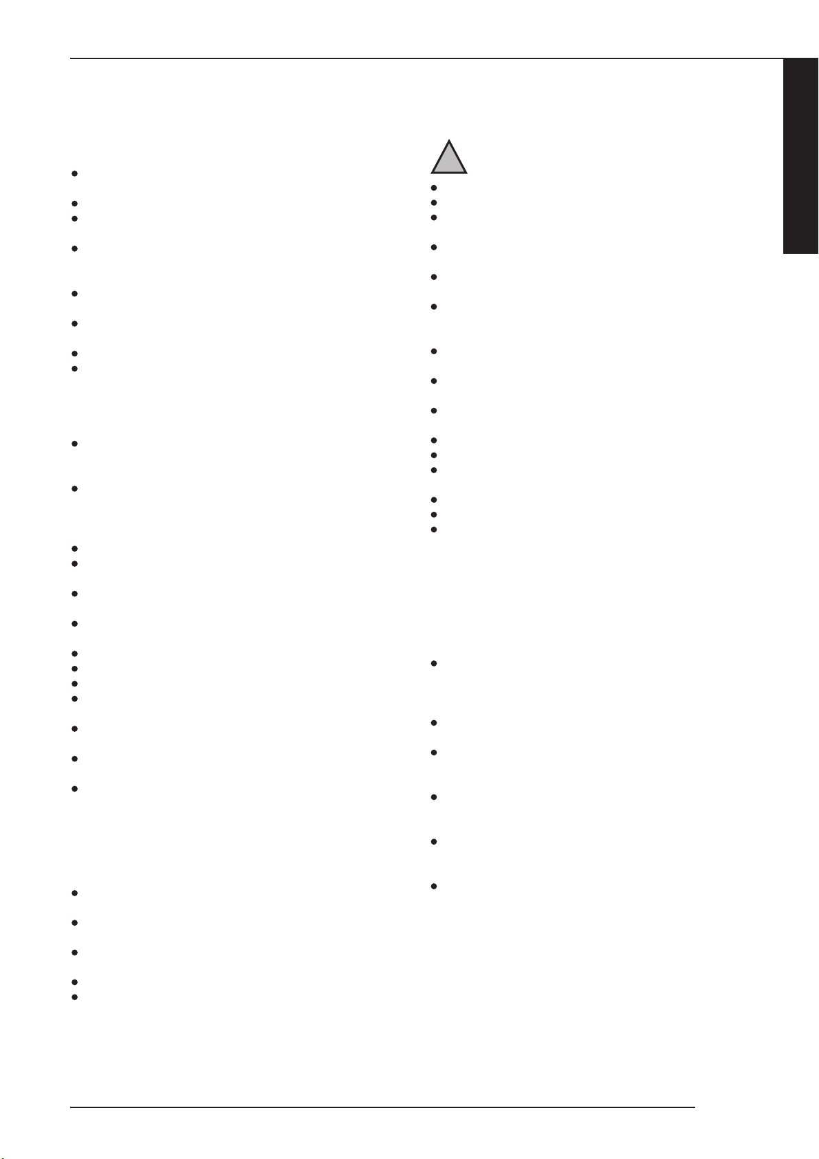
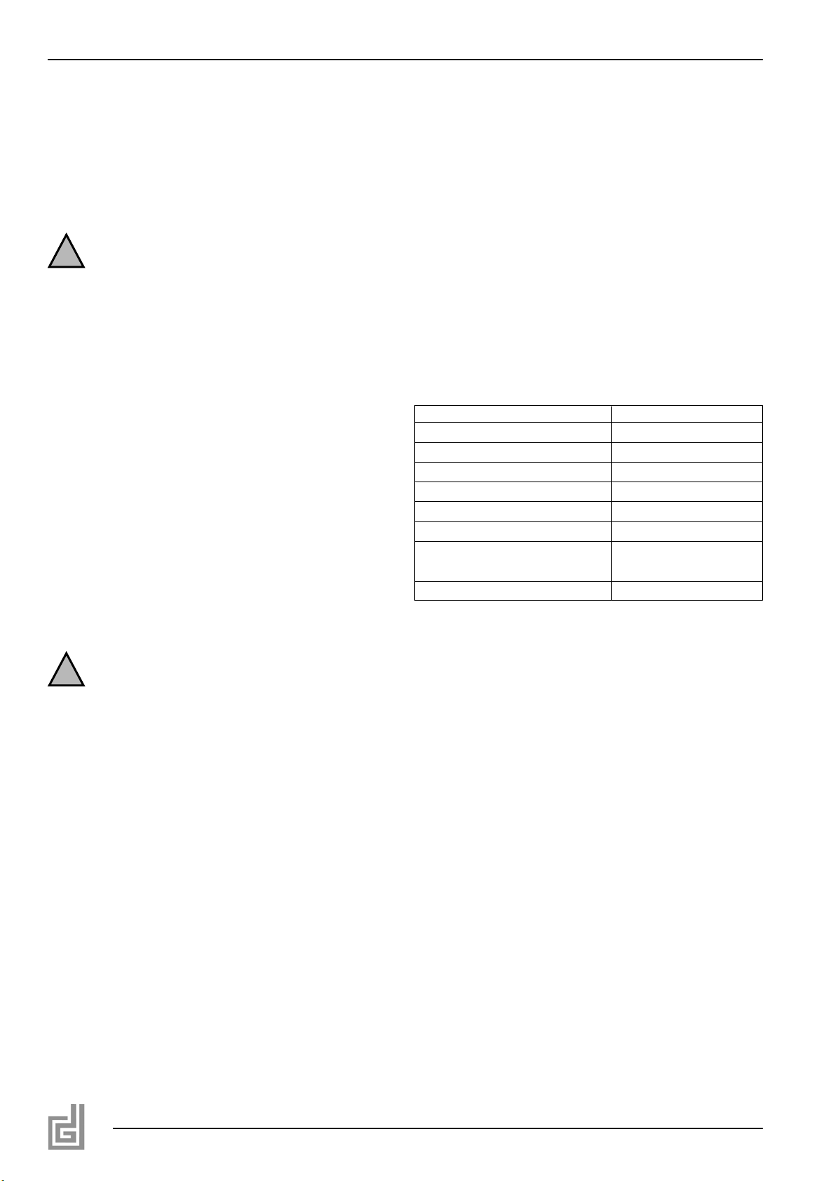
sluit de thermische veiligheidsklep (bijlage 3 guur 1) aan op
de aanvoer (D) van de koelspiraal. Zorg dat de pijl op de
veiligheidsklep richting de aansluiting van de koelspiraal
wijst (zie bijlage 2).
sluit de afvoer van de koelspiraal (E) aan op de waterafvoer
of riolering;
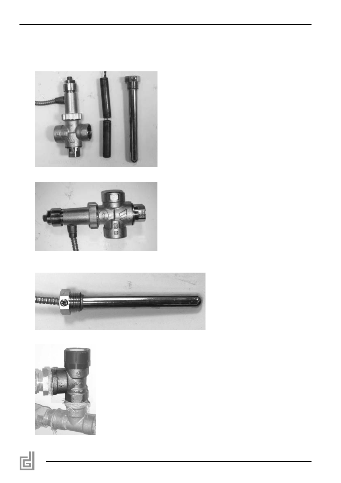
plaats de dompelhuls voor de voeler (guur 3) van de
thermische veiligheidsklep in de watermantel. Dit is de sok
links boven op de achterkant van de haard.
schuif de voeler van de thermische veiligheidsklep (A) in de
zojuist aangebrachte dompelhuls. Borg de voeler met de
schroef die in de dompelhuls zit (guur 3).
sluit de retour van het te verwarmen CV-water aan op de
3/4’’ sok; deze bevindt zich aan de onderzijde van de
watermantel (zie bijlage 2) (F).
sluit de aanvoer van het verwarmde CV-water aan op de
één van de aanvoeraansluitingen (3/4’’ sok). (zie bijlage 2)
Er zijn twee aanvoeraansluitmogelijkheden:
aanvoer 1 (C) zit bovenin de watermantel en aanvoer 2 (G)
zit onderaan de watermantel. Deze laatste aanvoer haalt het
warme water uit de bovenkant van de watermantel door middel
van een buis die door de watermantel loopt. Het aanvoerwater
van aanvoer 2 is daardoor minder heet dan het water uit
aanvoer 1. Afhankelijk van de retourtemperatuur is de maximale
temperatuur die uit aanvoer 2 gehaald kan worden 80 °C.
Nederlands
Dik Geurts
5
Let op
!

● Voor maximale prestatie wordt geadviseerd aanvoer 1 te
gebruiken. Als de hoge aanvoertemperatuur niet nodig is,
kan aanvoer 2 gebruikt worden zodat alle leidingen onder
aan de haard zitten.
● plaats het overdrukventiel (figuur 4) in de afvoer CV-leiding
van de haard en sluit deze aan op de waterafvoer of
riolering (zie ook hoofdstuk 3.5.2).
Tussen het overdrukventiel en de haard mogen geen
afsluiter of andere weerstanden geplaatst zijn!
5.6. Retourtemperatuurbewaking.
Om te voorkomen dat de warmtewisselaar te veel vervuild
is het belangrijk de haard zo snel mogelijk boven de
condensatietemperatuur van de rookgassen te brengen
en te houden. Dit dient te gebeuren doormiddel van een
retourtemperatuurbewaking welke ervoor zorgt dat de
retourtemperatuur naar de haard niet onder de 60˚C komt.
Een dergelijke unit is bij Dik Geurts te bestellen onder bestelnr.
45256.Het toepassen van een dergelijk systeem is verplicht om
de goede werking van dit product te garanderen. In bijlage 5 is
een voorbeeld installatieschema afgebeeld.
De verschillende componenten in dit schema zijn:
a) Retourtemperatuurbewaking(pompunit).
b) Expansievat.
c) Ontluchter.
d) Overdrukventiel(3bar)
e) Thermisch laadventiel.
f) Watertoevoer.
g) Circulatiepomp cv-systeem.
6. STOKEN
● Een Dik Geurts haard met CV wisselaar mag nooit zonder
water worden gestookt!
● Deze toestellen moeten eerst met water gevuld en ontlucht
worden en mogen pas in gebruik genomen worden als de
functionele installatie volledig afgerond is.
Zie de Gebruikershandleiding, hoofdstuk 5, voor het aansteken
en stoken van de haard.
7. OPLEVERING
U dient de gebruiker vertrouwd te maken met de haard. U dient
haar/hem te instrueren over onder meer de ingebruikname, het
stoken en het onderhoud.
● Instrueer de gebruiker over de haard.
● Wijs er bij ingebruikname op, dat
● bij de eerste keer stoken vluchtige componenten uitdampen
uit lak, materialen e.d.;
● de ruimte goed wordt geventileerd.
● Wijs op de noodzaak om het rookgaskanaal minstens
één keer per jaar te laten inspecteren en reinigen door een
specialist.
● Overhandig de gebruiker de gebruikershandleiding en de
installatiehandleiding (de installatiehandleiding dient bij het
toestel bewaard te blijven).
● Wijs de gebruiker op de noodzaak de warmtewisselaar te
reinigen (zie de gebruikershandleiding, hoofdstuk 2.1).
8. ONDERHOUD
In de Gebruikershandleiding wordt in Hoofdstuk 6, Onderhoud,
een aantal tips/instructies gegeven voor het onderhoud van de
haard. Tevens is vermeld hoe een aantal onderdelen vervangen
kan worden.
9. STORINGEN
In de Gebruikershandleiding, hoofdstuk 7, staat een tabel met
een overzicht van storingen die kunnen optreden, de mogelijke
oorzaak en de oplossing.
Bijlage 1 Meegeleverde onderdelen
In de onderstaande tabel staan de onderdelen vermeld die met
het toestel worden meegeleverd.
Tabel 1:
6
Let op
!
Let op
!
Onderdeel Aantal
Installatiehandleiding 1
Gebruikershandleiding 1
Handschoen 1
Asschep 1
Spuitflacon ruitenreiniger 1
Spuitbus met hittebestendige lak 1
Overdrukventiel 1
Thermisch laadventiel 1
Schoonmaakborstel 1

Bijlage 2 Aansluiting haard
Dik Geurts
7
Nederlands
570
800
390
180
780
196
830
440

8
Bijlage 3 Meegeleverde beveiligingen
14
Figuur1
Figuur2
Figuur3
Figuur4

Nederlands
Dik Geurts
9
Formulier voor oplevering Store H2O
Inbouw datum:
Klant: …………………………………..
Straat: ………………………………….. Huisnummer: ……………………………..
Postcode: ………………………………….. Plaatsnaam: ……………………………..
Schoorsteenhoogte: ……………………….….m Doorsnede: …………………………m
Materiaal : ……………………………. Kap?, zo ja type: …………………………..
Hoogte boven nok? …………....……………..m Klep?: …………………………..
Reinigingsmogelijkheid: …………………………….. Luchtoevoer: ………………………………
Ø cv aansluiting: …………………………mm Pompunit(verplicht) ………………………………..
Ø water aansluiting: …………………………mm Regeltemperatuur pompunit …………………………….°C
Verklaring van oplevering: Firmastempel:
De gebruiker verklaart hiermee dat het toestel
werkend is opgeleverd en hem/haar is uitgelegd
hoe het toestel te gebruiken en te onderhouden:
Datum en handtekening gebruiker: Datum en handtekening installateur:
Dik Geurts
The Netherlands
Bijlage 4 Formulier voor oplevering Store H2O

10
30-05-2012
Store
95˚C
60˚C
B
B
A
CD
E
F
G
Bijlage 5 Installatieschema

CONTENT..................................................................... 11
PREFACE .................................................................. 12
1. INTRODUCTION ............................................. 12
2. EC DECLARATION OF CONFORMITY STORE 12
3. SAFETY............................................................. 13
3.1 General.............................................................. 13
3.2 Regulations........................................................ 13
3.3 Precautions/safety instructions during installation.13
3.4 Additional safety regulations for stoves with CH
heat exchanger................................................... 13
3.5 Required safeguards explained in more detail..... 13
3.5.1 Thermal safety valve .......................................... 13
3.5.2 Overpressure relief valve.................................... 14
3.5.3 De-aeration ....................................................... 14
REMOVING THE PACKAGING.................................. 15
5. INSTALLATION ................................................ 15
5.1 Regulations........................................................ 15
5.2 Flue duct.......................................................... 145
5.3 Provisions for placing the fire ............................. 15
5.4 Placing the fire .................................................. 15
5.5 Connecting the fire ........................................... 15
6. BURNING.......................................................... 16
7. DELIVERY ........................................................ 16
8. MAINTENANCE................................................. 16
9. MALFUNCTIONS ............................................. 16
Appendix 1 Parts supplied........................................... 16
Appendix 2 connections fire + line drawing ................. 17
Appendix 3 safeguards supplied ................................. 18
Appendix 4 Form for final delivery of Store H2O.......... 19
Appendix 5 Installation overview .................................. 20
English
Dik Geurts
11

PREFACE
Dik Geurts, a fire manufacturer, develops and produces
products that comply with the highest quality, performance
and safety requirements. This will enable you to enjoy using
this product for many years to come. This fire is provided with
a CE mark. Wood burning fires that comply with the essential
requirements of the European Construction Products Directive,
including the requirements for safety, environment and energy
consumption, are entitled to carry the CE mark.
The fire is supplied with two manuals: the installation manual
and the user manual. The user manual will provide you with the
information that is required for a good and safe operation of the
fire. Carefully read the user manual prior to using the fire. Keep
the user manual AND the installation manual in a safe place. As
a user you are only entitled to perform the work described in
the user manual. Any other work requires a competent installer.
The installation manual will give you the information you need
to install the fire in such a way that it will operate properly and
safely. This manual discusses the installation of the fire and the
regulations that apply to the installation. It also provides you
with the technical specification of the fire. In case of questions
or doubts, please contact your installer.
Please carefully read and use this installation manual.
The following symbols are used in the manual to indicate
important information:
●Actions to be performed
You need these instructions to prevent fire,
personal injury or other serious damages.
After delivery, you should give the user manual and this
installation manual to the user.
1. INTRODUCTION
Congratulations on your purchase of this Dik Geurts fire. The
free-standing wood burning fire has an ingenious burning
system which ensures effective combustion and optimum
efficiency. The combustion chamber is lined with chamotte.
At the top you will find a so-called baffle plate to increase the
efficiency. The fire is equipped with a slide for air supply. Part
of the secondary air is continuously guided along the top of the
glass pane. The fire is only suitable to be filled with wood or
wood briquettes.
2. EC DECLARATION OF CONFORMITY STORE
The undersigned, representative of:
Manufacturer:
DRU Verwarming B.V.
PO Box 1021, NL-6920 BA Duiven
Ratio 8, NL-6921 RW Duiven
Hereby declares that the DRU issued wood fired heating
appliance was designed and constructed in such a way that
the appliance complies with the essential requirements of the
Construction Products Directive and that it is produced and
distributed in accordance with the requirements of the Belgian
Royal Decree of 12 October 2010 for the regulation of minimum
requirements concerning the efficiency and emission levels of
polluting substances for solid fuel heating appliances.
Product:
Free-standing, wood burning boiler made from steel plate.
Type:
Store
Applicable EEC directives:
89/106/EEC
Applied harmonized standards:
NEN/EN-13240 NEN/EN-13240/A2
Notified body:
S.G.S. Nederland B.V.
Leemansweg 51
Postbus 5252
6827 BX Arnhem
Distinguishing product features
TABLE see existing manual
Internal measures by the company guarantee that mass-
produced appliances comply with the essential requirements of
the prevailing EEC directives and the standards derived from
them.
This declaration will lose its validity if adjustments are made
to the appliance, without prior written permission by DRU
Verwarming B.V..
On behalf of DRU Verwarming B.V.
M.J.M. Gelten
General Director
12
Caution
!
Store
Fuel Wood
Operation Intermittent
Distance from combustible materials 700 mm
Emission of CO: 0.09 vol.% at 13%
combustion products O2
Flue gas temperature 266 °C
Nom. direct output 3.9 kW
Nom. output at water side 6.5 kW
Efficiency 76.1 %
Flue gas flow 10.6 g/s
Fine dust at 13% O2[mg/Nm3] 33
Diameter exit 180 mm
Fire safety compliant
Release of harmful substances none
Surface temperature compliant
Mechanical strength compliant
Weight of fire 270 kg
Minimum chimney draught 12 Pa
Water volume 25 litres
Suitable for a shared chimney No
Report EZKA/11/053-Z

3. SAFETY
Below you will find tips and instructions for a good operation of
your fire.
3.1 General
Safe installation of a Dik Geurts fire with heat exchanger for
solid fuels requires specialist know-how. This installation manual
is an essential part of the installation and operation instructions
for this type of fires. Therefore, please read this manual
carefully and observe all instructions!
Section 3.4 states additional safety regulations, specifically for
this type of appliances. Appendix 4 includes a check list that
will help you to install the appliance safely.
● Carefully read this chapter on safety, before you start
performing installation or maintenance work;
● Please observe the general regulations and the precautions/
safety instructions in this manual.
3.2 Regulations
Please install the appliance in accordance with the applicable
European, national, local and constructional (installation)
regulations.
3.3 Precautions/safety instructions during installation
● you should only install and maintain the fire if you are a
competent and recognised wood burning CH appliances
fitter;
● mount the fire on a floor of sufficient load-bearing strength;
● place the fire and/or the flue pipes in front of a wall made of
non-combustible material;
● if you discover flammable materials apply sufficient
heat-resistant isolation material;
● place the fire and/or the flue pipes at least 50 mm away
from the non-combustible wall;
● always place the fire and/or the flue pipes at a minimum
distance of 700 mm from combustible objects and/or
materials;
● mount the fire on a protective floor plate, in case of a
combustible floor. The floor plate made of non-combustible
material should extend at least 300mm at the front of the
fire, and it should be at least 300 mm wider than the fire;
● do not cover the fire and/or do not wrap it in an insulation
blanket or any other material;
● connect the fire to a suitable flue duct;
● have the flue duct inspected and cleaned in advance, by a
certified chimney sweeping company;
● do not make any changes to the fire yourself;
● only replace parts by original parts;
● make sure there is sufficient ventilation in the room where
the fire is installed.
3.4 Additional safety regulations for stoves with
CH heat exchanger
When installing a Dik Geurts fire with CH heat exchanger,
the following is essential:
● Installation without the supplied safety devices is not
permitted.
A Dik Geurts fire is always supplied with the following
safeguards:
- Safety heat exchanger (installed in the appliance);
- Thermal safety valve, with fluid filled detector and
capillary tube;
- Pressure relief valve, 3 bar
Check whether these safeguards, which are necessary for
the installation, are present and only then start performing
the installation!
● Taking the stove in operation without the certainty that all
safety components have been installed optimally, is
prohibited.
● Make sure there is a good provision for the aeration of the
heat exchanger. 3/8”.
● After installation, all safety components should be easily
accessible for inspection and service purposes.
● All components used for the installation at the water side
should at least be resistant to a temperature of 110 °C.
● All installed components that are not part of Dik Geurts’
scope of delivery, must be demonstrably suitable for
application in CH systems.
● When the appliance is used for the first time, all steps of the
operating manual must be observed.
● The user must be clearly instructed about the operation and
maintenance of the installation.
● Recommend the user to make annual appointments for
inspection and maintenance.
● The electrical connection must be realized in accordance
with the locally applicable standard.
If the installation does not comply with these points, any
form of product warranty will become invalid.
3.5 Required safeguards explained in more detail
3.5.1 Thermal safety valve
In accordance with standard EN 12828, the appliance is
protected against a water temperature that is too high. For this
purpose, a thermal safety valve is supplied.
The thermal safety valve must be mounted on a ‘cool’
location (< 50 °C) and must always be easily accessible.
A minimum water pressure of 2.0 bar must be guaranteed.
If the water pressure is not guaranteed, installation should only
take place on an open expansion system.
The safety valve is made with a very thin and fragile capillary
tube. It function is to transfer the pressure that is being
accumulated in the detector to the valve.
If the valve leaks due to damage, the operation is no longer
guaranteed and the valve should be replaced.
English
Dik Geurts
13
Caution
!
Caution
!
Caution
!
Caution
!
Caution
!

14
!Caution
The capillary tube of the thermal safety valve should never be
kinked, shortened or damaged.
The exit of the overflow pipe, must be mounted at a safe
location.
The exit of the overflow pipe should be mounted in such a way,
that no hazard can occur for the user. When this safeguard is
activated, water at approximately 100 °C will flow out of the
discharge pipe.
The connection of a thermal safety valve is displayed in a
diagram in appendix 4.
Make sure the exit of the discharge pipe of the thermal
safety valve can be checked for flow-through and leakage.
This connection pipe for the thermal safety valve must be
installed in a location where no frost can occur. Freezing
must be prevented at all times.
3.5.1.2 Operation of the thermal safety valve.
The thermal safety valve is a voltage free safeguard working on
cold mains water, which monitors the boiler temperature. When
the temperature at the valve’s detector becomes too high, the
valve will open. In that case, cold mains water is sent through
the cooling coil in order to discharge excess heat. Mixing of
mains water and water from the heating system is not possible,
as the cooling coil is separated from the boiler.
The safety valve opens at 95 °C (+/-3 °C) and makes sure that
the boiler temperature remains below 110 °C.
3.5.2 Overpressure relief valve
If the pressure gets too high, this is harmful to the system.
In order to prevent this, the system is supplied with an
overpressure relief valve.
The overpressure relief valve should be installed at all
times! Without this valve, it is impossible to guarantee a
safe operation of the system.
For a safe and correct operation of the overpressure relief
valve, take the following into account:
- connect the overpressure relief valve to the fire;
- for this, use a pipe with a minimum diameter of ½”;
- valves and resistors are not allowed in the pipe;
- use only one bend maximum.
The pipe from the overpressure relief valve to the discharge
must comply with certain requirements.
In case of a pipe with a maximum length of 2 metres:
- the maximum number of bends in this pipe is 2;
- the minimum diameter of this pipe ½”;
- it may not have any valves and resistors.
In case of a pipe with a maximum length of 4 metres:
- the maximum number of bends in this pipe is 3;
- the minimum diameter of this pipe ¾”;
- it may not have any valves and resistors.
If this valve has to be replaced, a valve with the exact same
specifications must be mounted.
Mount the blow-off pipe of the safety valve outside of the
direct reach of persons.
The safety valve must be mounted on an accessible location for
periodic tests.
3.5.3 De-aeration
A good de-aeration is very important for the system’s operation.
For a good de-aeration, proceed as follows:
- at the back of the appliance you will find a 3/8” female
thread bush;
- mount a de-aeration device here;
- provide the system in the supply and return of de-aeration
facilities.
If air accumulates in the system, the pump will be unable to
transport the CH water properly.
In that case, because of temperatures that are too high,
the temperature safeguard may be activated before the
appliance supplies hot water to the system.
3.5.4 Boiling-dry safeguard
In a fire half-filled with water, steam can be generated,
which could lead to dangerous situations.
This will be the case when radiators, buffer vessels or other
water-filled elements within the system are below the level
of the stove. In order to prevent this, place a safeguard that
monitors the water level.
Caution
!
Caution
!
Caution
!
Caution
!
Caution
!
Caution
!
Caution
!
Caution
!

Englis h
Dik Geurts
15
4. REMOVING THE PACKAGING
Pay attention to the following aspects whenremoving the re’s
packaging:
Check the appliance for transportation damage, never
install a damaged re;
Check if the box with parts is complete.
In Appendix 1 / Table 1 you can see which parts you
should have after removing the packaging;
As some part may have shifted in transit, check the position
of the bae plate and the charmotte plates. (see manual).
Check the operation of the air slide, door closure and, if
applicable, the rotation mechanism;
Remove any remaining blasting grit from the air slide;
For this, contact your supplier;
Dispose of packaging in accordance with local regulations.
5. INSTALLATION
5.1 Regulations
Please install the re in accordance with the applicable
national, local and constructional (installation) regulations.
Observe the regulations/instructions in this manual.
5.2 Flue duct
The following requirements apply to the ue duct:
the ue duct must be inspected in advance by a specialist;
the ue duct must be suitable for connection to a wood
burning appliance;
the re must be connected to a single, unshared ue duct;
the ue duct must be clean;
the ue duct must be gastight;
the ue duct’s diameter must be 180 mm;
the draught in the ue duct must be at least 12 Pascal;
in case of a duct with a draught that is too strong, it may be
necessary to install a ue valve;
ue pipes must be placed in such a way that they drain
towards the re;
the ue duct must be self-supporting and may not rest on
the re;
5.3 Provisions for placing the re
In order to place a free-standing re with an output of direct
heat AND hot water, the following provisions should be
available on the location of the re:
a water mains connection for the benet of the cooling
system;
a connection to the water discharge or sewerage for the
benet of the cooling system and the overpressure relief
valve.
Caution: Take a temperature of 100 °C in the discharge
system into account.
a supply and return for the CH system;
a possible power connection when the pump is used (this
pump is an essential part of the system, but is not part of
the scope of delivery!).
5.4 Placing the re
do not make any changes to the re;
mount the re on a oor of sucient load-bearing strength;
place the re and/or the ue pipes against a wall made of
non-combustible material;
place the re and/or the ue pipes at least 50 mm away
from the wall;
always place the re and/or the ue pipes at a minimum
distance of 800 mm from combustible objects and/or
materials;
place the re on a re-resistant oor plate extending in front
of the re in accordance with the applicable standard, if it is
placed on a oor made of combustible material;
do not cover the re and/or do not wrap it in an insulation
blanket or any other material;
observe the requirements for the ue gas channel, as stated
in paragraph 5.2.
Determine the location of the re; the dimensions can be
found in appendix 2.
If necessary, place the oor plate.
Place the re in its intended location.
Check if the chamotte plates and the bae plates are
placed correctly in the re (see user manual).
If necessary, correct the position of the plates.
Connect the re to the ue duct.
Place an optionally available inspection element, if the ue
pipe cannot be removed during maintenance. This 50cm
ue element contains an inspection hatch for the removal of
possible soot located on top of the steel bae plate in the
re.
5.5 Connecting the re
When connecting the re, proceed as follows (for a drawing of
the connections, see appendix 2):
connect the thermal safety valve (appendix 3 gure 1) to the
supply (D) of the cooling coil. Make sure the arrow on the
safety valve points towards the connection of the cooling
coil (see appendix 2).
connect the discharge of the cooling coil (E) to the water
discharge or sewer;
place the plunger bush for the detector (gure 3) of the
thermal safety valve in the water jacket. This is the sock (A)
at the top left on the back of the re.
slide the detector of the thermal safety valve in the plunger
bush just mounted. Secure the detector with the screw
located in the plunger bush (gure 3).
connect the return of the CH water to be heated to the
3/4’’ socket; it is located at the bottom of the water jacket
(see appendix 2) (F).
connect the supply of the heated CH water to one of the
supply connections (3/4’’ socket). (see appendix 2)
There are two options for connecting the supply:
supply 1 (C) at at the top of the water jacket and supply 2 (G) is
at the bottom of the water jacket. The latter supply retrieves the
hot water from the top of the water jacket by means of a tube
running through the water jacket. The supply water from supply
2 is therefore less hot than the water from supply 1. Depending
on the return temperature, the maximum temperature that can
be retrieved from supply 2 is 80 °C.
Caution
!

16
● For a maximum performance, we recommend using supply
1. If the high supply temperature is not needed, supply 2
can be used so that all pipes are at the bottom of the fire.
● place the overpressure relief valve (figure 4) in the CH
discharge pipe of the fire and connect it to the water
discharge or sewer (also see chapter 3.5.2).
Between the overpressure relief valve and the fire, no valves
or other resistors may be placed!
5.6. Return temperature monitoring
In order to prevent the heat exchanger from becoming too
contaminated, it is important to bring the fire as quickly as
possible above the condensation temperature of the flue gases
and to keep it at that temperature. This should be done by
means of return temperature monitoring, which will make sure
that the return temperature to the fire does not get below 60˚C.
Such a unit can be ordered at Dik Geurts under order no.
45256. Application of such a system is necessary in order to
guarantee a proper operation of this product. In appendix 5 you
can see an example installation diagram.
The various components in this diagram are:
a) Return temperature monitor (pump unit).
b) Expansion vessel.
c) De-aerator.
d) Overpressure valve (3 bar)
e) Thermal load valve.
f) Water supply.
g) Circulation pump CH system
6. BURNING
● A Dik Geurts stove with CH heat exchanger by never be
fired without water!
● These appliances should first be filled with water and
de-aerated, and may only be taken into operation when the
functional installation has been fully completed.
See the User Manual, chapter 5, for lighting and burning the
fire.
7. DELIVERY
You must explain to the user how to operate the fire. You
should instruct her/him for instance on using the appliance for
the first time, heating and maintenance.
● Instruct the user about the use of the fire.
● When the appliance is put into operation, point out that
● when the fire is heated up for the first time, volatile
components evaporate from paint, materials, etc.;
● the room should be well ventilated.
● Point out that the flue duct should be inspected and cleaned
at least once per year, by a specialist.
● Give the user manual and installation manual to the user (the
installation manual should be kept near the appliance).
● Point out to the user that the heat exchanger has to be
cleaned (see the user manual, chapter 2.1).
8. MAINTENANCE
There are a number of tips/instructions on the maintenance of
the fire in Chapter 6, Maintenance, of the User Manual. This
also explains how a number of parts can be replaced.
9. MALFUNCTIONS
In chapter 7 of the User manual you will find an overview of
malfunctions that might occur, the possible causes and the
remedies.
Appendix 1 Parts supplied
In the following table you can find the parts that are supplied
with the appliance.
Table 1:
Caution
!
Caution
!
Part Quantity
Installation manual 1
User manual 1
Glove 1
Ash pan 1
Glass cleaner spray bottle 1
Spray can of heat-resistant paint 1
Overpressure relief valve 1
Thermal load valve 1
Cleaning brush 1

English
Dik Geurts
17
Appendix 2 Connection fire
570
800
390
180
780
196
830
440

18
Appendix 3 Safeguards supplied
14
Figuur1
Figuur2
Figuur3
Figuur4
Figure 1
Figure 2
Figure 3
Figure 4
This manual suits for next models
1
Table of contents
Languages:
Other Dru Heater manuals
Popular Heater manuals by other brands

Beurer
Beurer IL 50 instruction manual

Polaris
Polaris 200 series instruction manual

Milwaukee
Milwaukee M18 0801-20 Operator's manual

Comfort Glow
Comfort Glow CGR18P OWNER'S OPERATION AND INSTALLATION MANUAL

Coates
Coates ST SERIES Installation, operation and maintenance

Toyostove
Toyostove Laser 560 Installation & operation instructions

NARVI
NARVI SAANA Installation and instruction manual

TESY
TESY CN04 YYZ MIS F Operation and storage manual

Sonnenkonig
Sonnenkonig BAGNO 450 instruction manual

Siemens
Siemens DE 12415 Installation and operating instructions

HUUM
HUUM STEEL Installation and operation manual

Sealey
Sealey CD2005.V3 instructions