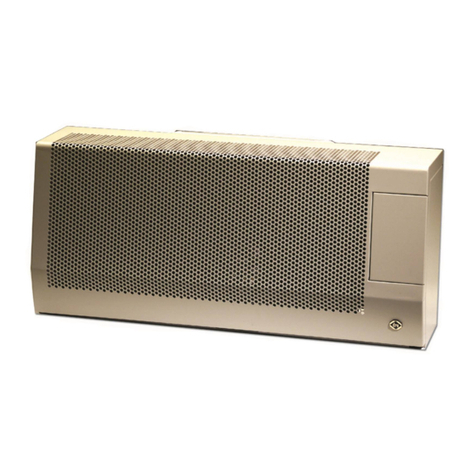
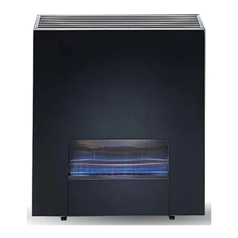
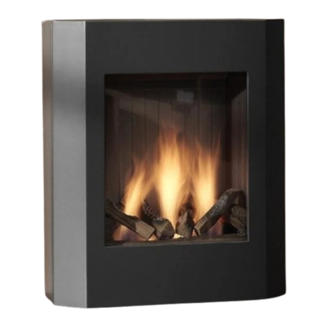
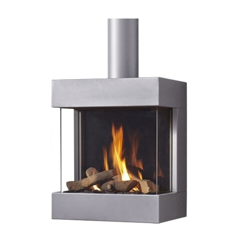
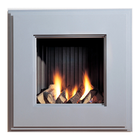
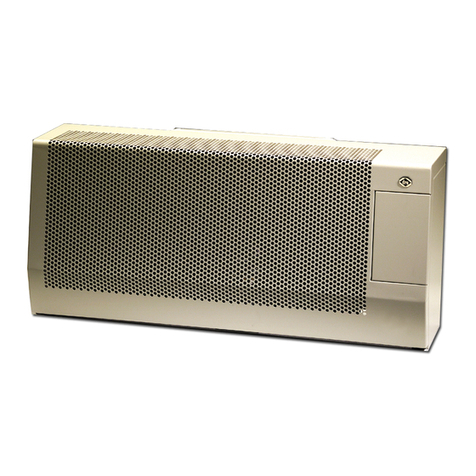
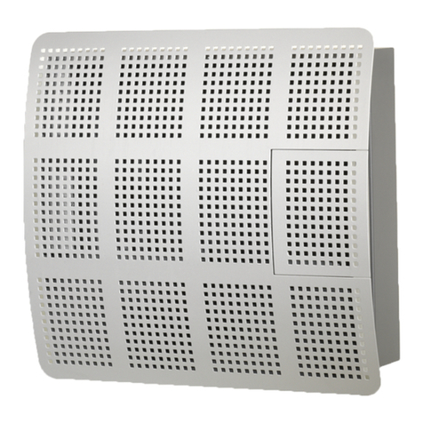
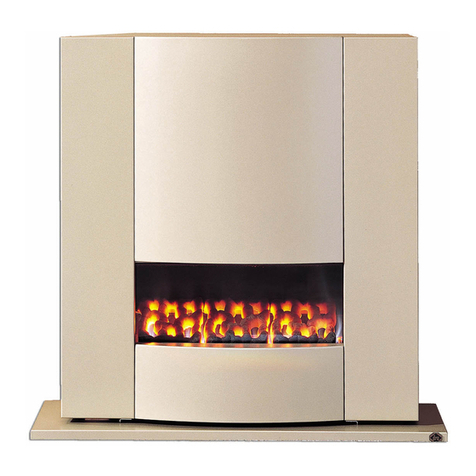
Dru Opera Deco-02 User guide

INSTALLATIEVOORSCHRIFT EN GEBRUIKERSHANDLEIDING
NL/BE
INSTRUCTIONS D’INSTALLATION ET MODE D’EMPLOI
FR/BE/LU/CH
INSTRUCTIONS FOR INSTALLATION AND OPERATIONS GB/IE
PIGALLE-01
OPÉRA DÉCO-02
Bewaar dit document zorgvuldig
Conservez soigneusement cette notice
Please retain this document carefully
957.887.03
DRU VERWARMING B.V.
HOLLAND


Nederlands
INHOUD
Woord vooraf.......................................................................2
Uitpakken ..............................................................................2
Aansluiten...............................................................................2
Installatievoorschrift ...........................................................2
Gassoort ...............................................................................2
Belangrijk ...............................................................................2
Plaatsbepaling .......................................................................2
Aansluiting op het schoorsteenkanaal.............................2
Plaatsen van de aluminium schermplaat ........................2
Aansluiting van de gastoevoer .........................................2
Gloeikooltjes plaatsen.........................................................3
Plaatsen van de mantel........................................................3
Vloerplaat...............................................................................3
Dit toestel is voorzien van een TTB...............................3
Oorzaak werking van de TTB kan zijn ..........................3
Maatregelen tegen het werken van de TTB .................3
Uitvoering van de TTB .......................................................3
Gebruikershandleiding ........................................................4
Ontsteken ..............................................................................4
Temperatuur regelen ..........................................................4
Uitschakelen ..........................................................................4
Belangrijk................................................................................4
Eco control pack ..................................................................4
Algemene opmerkingen......................................................5
Onderhoud en reiniging .....................................................5
Verkleuring van wanden en plafonds .............................5
Eerste maal stoken...............................................................5
Extra bescherming ...............................................................5
Afdanken ...............................................................................5
Garantie ................................................................................5
Technische gegevens ..........................................................6
Hoofdafmetingen................................................................19
Pigalle
INHOUD
1
CE-VERKLARING
Door bedrijfsinterne maatregelen is gewaarborgd dat door DRU geproduceerde toestellen aan de essentiële eisen van de
verordening betreffende gasverbrandingstoestellen en daarbij toegepaste normen voldoen. Deze verklaring verliest haar
geldigheid als zonder schriftelijke toestemming van DRU wijzigingen aan het toestel worden aangebracht. Een kopie van het
CE keuringscertificaat is te downloaden via www.druservice.com.
Product: Gas verwarmingstoestel
Type: Opéra Déco 02, Pigalle 01
Van toepassing zijnde EG- verordening: 2016/426/EU
Toegepaste geharmoniseerde normen: NEN-EN-613; NEN-EN-613/A1
Conformiteitsbeoordelingsinstantie: Kiwa 0063
R.P. Zantinge
General Manager
Postbus 1021, 6920 BA Duiven
Ratio 8, 6921 RW Duiven
www.drufire.com

Woord vooraf
Geachte klant,
Vriendelijk bedankt voor de aankoop van dit DRU
product. Onze producten zijn ontwikkeld en gefabriceerd
volgens de hoogst mogelijke kwaliteits-, prestatie- en
veiligheidseisen. Hierdoor kunt u rekenen op jarenlang
probleemloos gebruiksplezier.
In dit boekje vindt u instructies voor installatie en
gebruik van uw nieuwe toestel. Lees de instructies en
gebruikershandleiding goed door, zodat u zich vertrouwd
maakt met het toestel. Wilt u meer ondersteuning, neem
dan contact op met uw leverancier.
Uitpakken
Wanneer u klaar bent met uitpakken, dient de verpakking
via de reguliere weg te worden afgevoerd.
Aansluiten
Dit toestel dient te worden aangesloten door een bevoegd
installateur.
INSTALLATIEVOORSCHRIFT
Gassoort
Dit toestel is bestemd voor het land en geschikt voor
de gassoort dat is vermeld op de typeplaat. Controleer
of de gassoort, gasdruk ter plaatse en branderdruk
overeenkomen met de vermelding op het typeplaatje.
Houdt u aan de gasinstallatievoorschriften en eventuele
plaatselijke voorschriften. Het toestel dient door een
bevoegd installateur te worden aangesloten.
Belangrijk
• Zorg ervoor dat evt. overgordijnen of andere brandbare
materialen minstens 50 cm van het toestel verwijderd zijn.
• Let op! Aanraking van hete delen kan brandblaren
veroorzaken!
• Installatie en onderhoud van het toestel dienen door een
professioneel gecertificeerd vakman te worden uitgevoerd
welke over bewezen kennis en aantoonbare bekwaamheid
beschikt. Een professionele vakman houdt rekening met
alle technische aspecten zoals warmte afgifte, gasaansluiting
en met verbrandingsgasafvoer vereisten. Daar waar het
installatievoorschrift niet duidelijk is dient de nationale/
lokale regelgeving te worden gevolgd.
• Het plaatsen van een z.g. stoffilter op of onder de mantel
is niet toegestaan.
• Natte kleding, handdoeken e.d. niet op de kachel te
drogen hangen!
Plaatsbepaling
• Het toestel mag alleen geplaatst worden in een goed
geventileerde ruimte, zodat er altijd voldoende
luchttoevoer is.
• Het toestel mag niet geplaatst worden tegen een wand
van brandbaar materiaal tenzij deze door een isolatieplaat
is beschermd.
• Houd de verbinding tussen pijpmond en schoorsteen-
kanaal zo kort en zo recht mogelijk. Het gasregelblok
moet goed bereikbaar zijn.
• De minimum afstand van de achterplaat tot de muur
bedraagt 70 mm.
• Het toestel is ontworpen voor sfeer- en
verwarmingsdoeleinden. Dit houdt in dat alle zichtbare
oppervlaktes, inclusief de ruit heter dan 100 °C kunnen
worden. Het is aan te bevelen altijd een afschermrooster
voor het toestel te plaatsen als er kinderen, bejaarden of
mindervaliden in dezelfde ruimte als het toestel aanwezig
zijn. Indien regelmatig kwetsbare personen zonder
toezicht in de ruimte aanwezig kunnen zijn, dient een vaste
afscherming rondom het toestel te worden gemonteerd.
Aansluiting op het schoorsteenkanaal
• Laat eerst het schoorsteenkanaal vakkundig reinigen
alvorens het toestel hierop aan te sluiten. Hoewel het
toestel kan werken met een zeer kleine schoorsteentrek
adviseren wij een jaarlijkse controle van de schoorsteen
op eventuele verstoppingen e.d.
• De inwendige diameter van de pijpmond is 101 mm.
• Gebruik voor de verbinding pijpmond-schoorsteenkanaal
corrosievast materiaal.
• Deze verbindingspijp mag nooit lager geplaatst worden
dan de pijpmond van de kachel.
• Leg een langere verbindingspijp van de pijpmond naar het
schoorsteenkanaal onder afschot (2%) in de richting van
de pijpmond.
Plaatsen van de aluminium schermplaat
Deze dient bij installatie van het toestel onder de voet
van het binnenwerk geplaatst te worden. De plaat zover
naar achteren schuiven dat de voorzijde gelijk ligt met de
voorzijde van de plaatstalen voet.
Aansluiting van de gastoevoer
Het toestel wordt geleverd met 3/8” binnendraad.
Gebruik in de toevoerleiding een gekeurde aansluitkraan
met koppeling (voor België moet deze B.G.V. gekeurd
zijn). Verder geldt:
• Ontlucht de toevoerleiding voordat het toestel wordt
vastgekoppeld.
• Vermijd spanningen op het gasregelblok en de leidingen.
• Controleer de aansluitingen op gasdichtheid.
INSTALLATIEVOORSCHRIFT
2

Nederlands
• Controleer of de gas voordruk en branderdruk
overeenkomen met de vermelding op de typeplaat.
Corrigeer indien nodig de branderdruk met behulp van
de regelschroef. De regelschroef voor de branderdruk
bevind zich achter het kapje op het gasregelblok. Dit
kapje kan verwijderd worden door schroef uit te
draaien en de lip aan de linkerzijde met behulp van een
schroevendraaier los te klikken.
Gloeikooltjes (Niet van toepassing op Pigalle)
Deze zijn vanuit de fabriek reeds gemonteerd. Wanneer
deze moeten worden vervangen ga dan als volgt te werk:
• Verwijder de 8 moeren.
• Glasraam afnemen.
• Verwijder de kapotte gloeikooltjes.
• Plaats de gloeikooltjes gelijkmatig verdeeld op het
raamwerk in de verbrandingskamer ( fig. 1).
• Glasraam terug plaatsen.
• 8 moeren vast draaien.
Plaatsen van de mantel
Bij plaatsing van de mantel dienen de pennen op de
voetsteunen van het toestel in de gaten aan de onderzijde
van het mantelfront gecentreerd te worden en dient de
achterrand van de mantel in de mantelsteunen te vallen.
Vloerplaat
De vloerplaat onder het toestel plaatsen, zodanig dat de
uitsparingen om de plaatstalen voeten van het binnenwerk
vallen.
Dit toestel is voorzien van een TTB
De TTB is een Thermische Terugslag Beveiliging die
reageert op het terugstromen van verbrandingsgassen
via de trekonderbreker van het toestel in de woonkamer.
Bij terugslag van verbrandingsgassen wordt het thermo-
koppel onderbroken door de TTB, waardoor de gas-
toevoer naar de branders afgesloten wordt.
Met deze beveiliging wordt voorkomen dat verbrandings-
gassen voor langere tijd de woning instromen. De veilig-
heid reset zich na enkele minuten vanzelf en het toestel
kan opnieuw ontstoken worden.
Oorzaak werking van de TTB kan zijn:
• Er is totaal geen of te weinig toevoer van verse lucht in
de woning (alle kieren afgedicht en ventilatie-openingen
afgesloten).
• De doorlaat van het schoorsteenkanaal is geheel of
gedeeltelijk geblokkeerd.
• De schoorsteenuitmonding is niet juist uitgevoerd,
waardoor valwinden in het schoorsteenkanaal kunnen
ontstaan.
Maatregelen tegen het werken van de TTB
Na afkoeling van de TTB kan het toestel opnieuw
worden ontstoken.
Indien de beveiliging opnieuw werkt kan er een raam of
luchttoevoer opening geopend worden.
Wordt met deze handeling de storing opgeheven, dan
betekent dit dat de woning hermetisch dicht is en het
toestel zijn verbrandingsgassen niet via de schoorsteen
kan afvoeren. Er zal een luchttoevoeropening in de
woning moeten worden aangebracht of open gehouden.
Blijft de beveiliging na deze handelingen nog werken, dan
dienen de bovengenoemde andere mogelijke oorzaken te
worden onderzocht en opgeheven.
De beveiliging mag niet buiten werking worden gesteld.
Let op: Bij een herhaald in werking treden van
de TTB, moet men contact opnemen met een
bevoegd gasinstallateur.
Uitvoering van de TTB
De TTB beveiliging is van enkele speciale componenten
voorzien die bij eventuele vervanging ook weer toegepast
dienen te worden.
Het aanbrengen van een “standaard” thermokoppel
wordt ten zeerste afgeraden.
Pigalle
INSTALLATIEVOORSCHRIFT
3
38c-993
fig. 3

4
GEBRUIKERSHANDLEIDING
Ontsteken
De ontsteekknop A heeft drie standen namelijk:
O stand knop wijst naar O
Waakvlamstand knop wijst naar
Vol stand knop wijst naar
Draai de Ontsteekknop vanaf O stand linksom,
tevens goed indrukken en doordraaien naar de
waakvlamstand . Door het draaien aan de knop wordt de
waakvlambrander door een elektrische vonk ontstoken.
Als de waakvlam brandt, de knop nog ca 10 sec. ingedrukt
houden en dan loslaten. De waakvlambrander is zichtbaar
aan de zijkant achter het glasraam. Als de waakvlam
niet in één keer ontsteekt, kan bovenstaande handeling
meteen herhaald worden door met ingedrukte knop
terug te draaien richting O en weer linksom richting
waakvlamstand. Na het loslaten van de ansteekknop
moet de waakvlam blijven branden. De aansteekknop
vervolgens verder draaien naar volstand . Afhankelijk
van thermostaatknop B zal de hoofdbrander ontstoken
worden.
Temperatuur regelen
De stand van de thermostaatknop B bepaalt de
temperatuur in de kamer. Stand 6 geeft de hoogste
temperatuur en stand 1 de laagste. De thermostaat regelt
modulerend tussen “volstand” en “kleinstand” van de
brander. De thermostaat houdt de kamer automatisch op
de gewenste ingestelde temperatuur.
Uitschakelen
Draai de ontsteekknop A terug naar de Waakvlamstand
(symbool ), alleen de waakvlam blijft branden. Om het
toestel volledig uit te zetten drukt u vervolgens knop A in
en draait hem terug naar stand O.
Belangrijk
Een ingebouwde veiligheidsvergrendeling treedt in
werking wanneer het toestel op ,,UIT” (stand O) wordt
gezet. Wacht daarom 5 minuten alvorens het toestel
opnieuw te ontsteken. Probeer binnen deze tijd niet de
aansteekknop in te drukken, daar deze door de veiligheids-
vergrendeling geblokkeerd is. Forceer de knop niet,
omdat het mechanisme dan kan worden beschadigd.
Eco control pack
Voor dit toestel is een los verkrijgbare “Eco control pack”
met afstandsbediening beschikbaar. Het “Eco control pack”
is nodig om het optimale uit uw toestel te halen.
Bij deze set zit een ontvanger, plaats deze in het daarvoor
bestemde bakje.
Deze bevind zicht onder het gasregelblok, deze is te
bereiken door de mantel weg te nemen.
Voorkom dat de kabels tegen de hete delen van het
binnenwerk aankomen.
Let op: Bij een herhaald in werking treden van
de TTB, moet men contact opnemen met een
bevoegd gasinstallateur.
GEBRUIKERSHANDLEIDING
Ontsteken
De ontsteekknop A heeft drie standen namelijk:
O stand knop wijst naar O
Waakvlamstand knop wijst naar
Vol stand knop wijst naar
Draai de Ontsteekknop vanaf O stand linksom,
tevens goed indrukken en doordraaien naar de
waakvlamstand . Door het draaien aan de knop
wordt de waakvlambrander door een elektrische
vonk ontstoken. Als de waakvlam brandt, de knop
nog ca 10 sec. ingedrukt houden en dan loslaten.
De waakvlambrander is zichtbaar aan de zijkant
achter het glasraam. Als de waakvlam niet in één
keer ontsteekt, kan bovenstaande handeling
meteen herhaald worden door met ingedrukte
knop terug te draaien richting O en weer linksom
richting waakvlamstand. Na het loslaten van de
ansteekknop moet de waakvlam blijven branden.
De aansteekknop vervolgens verder draaien naar
volstand . Afhankelijk van thermostaatknop B zal
de hoofdbrander ontstoken worden.
Temperatuur regelen
De stand van de thermostaatknop B bepaalt de
temperatuur in de kamer. Stand 6 geeft de hoogste
temperatuur en stand 1 de laagste. De thermostaat
regelt modulerend tussen “volstand” en
“kleinstand” van de brander. De thermostaat
houdt de kamer automatisch op de gewenste
ingestelde temperatuur.
Uitschakelen
Draai de ontsteekknop A terug naar de
Waakvlamstand (symbool ), alleen de waakvlam
blijft branden. Om het toestel volledig uit te zetten
drukt u vervolgens knop A in en draait hem terug
naar stand O.
Belangrijk
Een ingebouwde veiligheidsvergrendeling treedt in
werking wanneer het toestel op ,,UIT” (stand O)
wordt gezet. Wacht daarom 5 minuten alvorens
het toestel opnieuw te ontsteken. Probeer binnen
deze tijd niet de aansteekknop in te drukken, daar
deze door de veiligheidsvergrendeling geblokkeerd
is. Forceer de knop niet, omdat het mechanisme
dan kan worden beschadigd.
Eco control pack
Voor dit toestel is een los verkrijgbare “Eco control
pack” met afstandsbediening beschikbaar. Het
“Eco control pack” is nodig om het optimale uit uw
toestel te halen.
Bij deze set zit een ontvanger, plaats deze in het
daarvoor bestemde bakje.
Art 2-01: Het bakje bevindt zich links van het
gasregelblok.
Art 3-01, 4-01, 5-01, 6-01, 8-02, 10-02: Het bakje
bevindt zich Onder het gasregelblok.
Voorkom dat de kabels tegen de hete delen van
het binnenwerk aankomen.
1
6
2
3
4
5
A
B
38P-0744/0

ALGEMENE OPMERKINGEN
Onderhoud en reiniging
Uw toestel dient eenmaal per jaar door een gekwalificeerd
bedrijf te worden gecontroleerd, en waar nodig, hersteld
of gereinigd. De controle en het onderhoud dient in
ieder geval een goede en veilige werking van het toestel
te omvatten. U kunt hiervoor gebruik maken van uw
gasinstallateur of een gespecialiseerd onderhoudsbedrijf.
Het verdient aanbeveling om vóór en tijdens het
stookseizoen het toestel enkele malen stofvrij te maken.
Op de binnenkant van het glasraam kan zich na verloop
van tijd aanslag vormen U kunt deze verwijderen met een
vochtige doek of met een nietkrassend reinigingsmiddel
(zoals koperpoets). Doe dit zodra aanslag verschijnt, zodat
deze niet kan inbranden en reinigen onmogelijk wordt.
Bij het reinigen van de mantel geen bijtende of schurende
middelen gebruiken. Lakbeschadigingen, bijvoorbeeld door
het plaatsen van voorwerpen op of tegen de mantel, vallen
buiten de garantie.
Let op: Bij het vervangen van het thermoelement
moet de wartel in het gasregelblok handvast gedraaid
worden, waarna deze met een steeksleutel een kwartslag
aangedraaid moet worden.
Verkleuring van wanden en plafonds
Bruinverkleuring is een vervelend probleem en is moeilijk
op te lossen. Bruinverkleuring kan worden veroorzaakt
door onder andere stofverbranding veroorzaakt door te
weinig ventilatie, door het roken van sigaretten of het
branden van kaarsen.
Deze problemen kunnen worden voorkomen door:
Het vertrek waar het toestel zich bevind goed te
ventileren. Een goede richtlijn hiervoor is:
Bij nieuwbouw : 3.24 m3/ uur per m2
vloeroppervlak van een vertrek.
Bij bestaande bouw : 25.20 m3/ uur voor een vertrek.
Maak zo weinig mogelijk gebruik van kaarsen en
olielampjes en houd het verbrandingslontje zo kort
mogelijk. Deze “sfeerbrengers” zorgen voor aanzienlijke
hoeveelheden vervuilde en ongezonde roetdeeltjes in
uw woning. Rook van sigaretten en sigaren bevat o.a.
teerstoffen die bij verhitting eveneens op koudere en
vochtige muren zullen neerslaan. Bij een nieuw gemetselde
schouw of na een verbouwing wordt aanbevolen minimaal
6 weken te wachten voordat men gaat stoken, het
bouwvocht moet namelijk geheel verdwenen zijn uit
wanden, vloer en plafond.
Eerste maal stoken
Tijdens de eerste maal stoken kan er een onaangename
geur ontstaan, die wordt veroorzaakt door het uitdampen
van de lak. Dit verdwijnt na enkele uren. Daarom raden
wij u aan het toestel de eerste maal op de hoogste stand
te stoken terwijl u tevens het vertrek waarin de kachel
staat goed ventileert.
Extra bescherming
Indien het toestel in een vertrek geïnstalleerd wordt
waar jonge kinderen of hulpbehoevende mensen zonder
toezicht verblijven, is het wenselijk het toestel af te
schermen.
Afdanken
Indien u het toestel vervangt of verwijdert, moet u
het toestel via de reguliere weg afvoeren. Voordat tot
demontage wordt overgegaan eerst de aansluitkraan met
koppeling dichtdraaien. De koppeling tussen aansluitkraan
en toestel losdraaien. Het gehele toestel kan nu worden
gedemonteerd en afgevoerd.
Garantie
De garantie op uw DRU toestel wordt verleend via uw
leverancier. In geval van storingen dient u altijd met hem
contact op te nemen. Uw leverancier zal DRU inschakelen
indien hij dit noodzakelijk acht. De fabrieksgarantie op uw
toestel bedraagt 2 jaar na datum van aankoop.
Nederlands
ALGEMENE OPMERKINGEN
Pigalle
5

6
TECHNISCHE GEGEVENS
Typeaanduiding(en):
Gassoort: Symbool G25/
G25.3* G20 G31 Eenheid
Indirecteverwarmingsfunctionaliteit Nee Nee Nee
Directewarmteafgifte 7,0 7,3 6,8 kW
Indirectewarmteafgifte ‐‐‐kW
UitstootbijruimteverwarmingNox112,3 118,9 125,7 mg/kWhinput
(GCV)
Warmteafgifte
Nominalewarmteafgifte Pnom 7,0 7,3 6,8 kW
Minimalewarmteafgifte(indicatief) Pmin 1,8 1,9 1,7 kW
Technischegegevens
Nominalebelasting(Hs) 8,7 9,1 7,7 kW
Nominalebelasting(Hi) 7,8 8,2 7,1 kW
Gasverbruikvolstand 927 862 280 l/h
Gasverbruikkleinstand 241 225 77 l/h
Branderdrukvolstand 14,7 11,8 23,2 mbar
Branderdrukkleinstand 1,2 1,0 1,9 mbar
Branderspuitstuk 7xØ1,01 7xØ1,01 7xØ0,63 mm
Kleinstelspuitstuk 1,20 1,20 0,80 mm
Rendementsklasse(EN613) 1 1 1
Nuttigrendement(NCV)
Nuttigrendementbijnominalewarmteafgifteηth,nom 89,4 89,0 95,4 %
Nuttigrendementbijminimalewarmteafgifte
(indicatief)ηth,min 85,3 85,6 89,6 %
Aanvullendelektriciteitsverbruik
Bijnominalewarmteafgifteelmax ‐‐‐kW
Bijminimalewarmteafgifte elmin ‐‐‐kW
Instand‐bymodus elSB ‐‐‐kW
Vermogenseisvoordepermanentewaakvlam
Vermogenseisvoordepermanentewaakvlam(indien
vantoe
p
assin
g
)Ppilot ‐‐‐kW
Energie-efficiëntie
Energie-efficiëntie-index EEI 89 89 95
Energie-efficiëntieklasse AAA
Nee
Nee
Ja
Ja**
Ja**
Ja**
Ja**
Ja**
Ja**
*DittoestelisgeschiktvoorG25.3metdesamenstellingvolgensNTA8837
**DezefunctieszijnalleenvantoepassingincombinatiemethetlosverkrijgbareEcocontrolpack.
Déco‐02/Pigalle‐01
Metdeoptievanafstandsbediening
Typewarmteafgifte/sturingkamertemperatuur
Eentrapswarmteafgifte,geensturingvandekamertemperatuur
Tweeofmeerhandmatigintestellentrappen,geensturingvandekamertemperatuur
Metmechanischesturingvandekamertemperatuurdoorthermostaat
Metelektronischesturingvandekamertemperatuur
Metelektronischesturingvandekamertemperatuurplusdag‐tijdschakelaar
Metelektronischesturingvandekamertemperatuurplusweek‐tijdschakelaar
Anderesturingsopties
Sturingvandekamertemperatuur,metaanwezigheidsdetec�e
Sturingvandekamertemperatuur,metopenraamdetec�e

Pigalle
7
Français
TABLE DES MATIÈRES
TABLE DES MATIÈRES
Introduction...........................................................................8
Déballage de l’appareil ........................................................8
Branchement .........................................................................8
Instructions d’ installation..................................................8
Sorte de gaz...........................................................................8
Important ...............................................................................8
Emplacement .........................................................................8
Raccordement au canal de la cheminee .........................8
Placement d’une plaque de protection
en aluminium .........................................................................8
Raccordement à la conduite de gaz.................................9
Placement des charbons ....................................................9
Placement de l’habillage .....................................................9
Plaque de base .....................................................................9
L’appareil est prévu d’une PRT.........................................9
Causes de la mise en marche de la PRT .......................9
Mesures à prendre après le fonctionnement
de la PRT................................................................................9
Exécution de la PRT..........................................................10
Manuel de l’utilisateur.......................................................10
Allumage ..............................................................................10
Réglage de température. ..................................................10
Arrêt......................................................................................10
Important .............................................................................10
Eco control pack ................................................................10
Remarques générales.........................................................11
Entretien et nettoyage ......................................................11
Changement de couleur des murs et plafond.............11
La première mise en service ...........................................11
Protection supplémentaire...............................................11
Mise aux déchets ..............................................................11
Garantie ..............................................................................11
Détails technique................................................................12
Dimensions principales .....................................................19
DÉCLARATION CE
Par des mesures internes à l’entreprise, nous garantissons que les appareils produits par DRU satisfont aux exigences
essentielles du règlement relatif aux appareils à combustion de gaz et aux normes qui en découlent. La présente déclaration
n’est cependant plus valable si des modifications sont apportées à l’appareil sans l’accord préalable écrit de DRU. Une copie
du certificat de contrôle de qualité est à télécharger par l’intermédiaire de www.druservice.com.
Produit: Appareil de chauffage au gaz
Type: Opéra Déco 02, Pigalle 01
Règlement CE applicable : 2016/426/EU
Normes harmonisées appliquées : NEN-EN-613; NEN-EN-613/A1
Organisme d’évaluation de conformité : Kiwa 0063
R.P. Zantinge
Directeur général
Boîte postale 1021, 6920 BA Duiven
Ratio 8, 6921 RW Duiven
www.drufire.com

Introduction
Cher client,
Nous vous remercions d’avoir acheté cet article fabriqué
par DRU. Tous nos articles sont conçus et fabriqués dans
le respect des consignes les plus sévères de qualité, de
performance et de sécurité. Ainsi, vous êtes assuré de
profiter de votre achat pendant des années, sans aucun
problème.
Dans ce livret, vous trouverez des instructions pour
l’installation et l’utilisation de votre nouveau foyer.
Lisez avec attention toutes les instructions ainsi que le
manuel de l’utilisateur afin de vous familiariser avec cet
appareil. Pour toute assistance supplémentaire, veuillez
contacter votre fournisseur.
Déballage de l’appareil
Après avoir déballé l’appareil, jetez l’emballage
conformément aux règles en vigueur.
Branchement
Cet appareil doit être branché par un installateur
compétent.
INSTRUCTIONS D’INSTALLATION
Sorte de gaz
Cet appareil est destiné au la pays et adapté au type de gaz
spécifié sur la plaque signalétique.
Vérifiez que le type, la pression et pression du brûleur
du gaz sur les lieux de l’installation sont conformes aux
informations figurant sur la plaquette de type. Respectez
les consignes d’installation relatives au gaz ainsi que toute
prescription locale. L’appareil doit être branché par un
installateur compétent.
Important
• Veillez à ce que les rideaux ou tout autre matériel
inflammable soient au moins à une distance de 50 cm de
l’appareil.
• Attention: vous pouvez vous brûler si vous touchez des
parties chaudes de l’appareil!
• Un spécialiste professionnel tient compte de l’ensemble
des aspects techniques tells que la puissance thermique,
le raccordement au gaz ainsi que des exigences en
matière d’évacuation des gaz de combustion. Le manuel
d’installation contient les informations dont vous avez
besoin pour installer l’appareil de manière à ce qu’il
fonctionne correctement et en toute sécurité. Là où la
notice d’installation n’est pas claire, la réglementation
nationale/locale doit être observée.
• Il est interdit d’installer ce qu’on appelle un filtre à
poussières sur ou en dessous du manteau.
• Ne mettez pas de vêtements, serviettes, etc. à sécher sur
le poêle.
Emplacement
• L’appareil doit être installé uniquement dans un local bien
ventilé afin de garantir une amenée d’air suffisante.
• L’appareil ne peut pas être placé contre un mur composé
ou recouvert de matériaux inflammables, à moins que
celui-ci ne soit protégé par une plaque en matériau isolant.
• Gardez la connection entre le buselot d’évacuation du
foyer et le canal de la cheminée aussi courte et aussi
droite que possible. La vanne thermostatique de réglage
doit rester accessible.
• La distance minimum à respecter entre l’arrière de
l’appareil et le mur est de 70 mm.
• L’appareil est conçu à des fins d’ambiance et de chauffage.
Ceci implique que toutes les surfaces visibles, y compris
la vitre, peuvent atteindre une température supérieure à
100ºC. Il est recommandé de toujours placer une grille
de protection devant l’appareil, si des enfants, personnes
âgées ou personnes moins valides sont présents dans la
même pièce que l’appareil. Si des personnes fragiles sans
surveillance peuvent être presents régulièrement dans la
pièce, une protection fixe doit être montée autour de
l’appareil.
Raccordement au canal de la cheminee
• Faites nettoyer soigneusement et dans les règles de l’art le
conduit de fumées avant d’y raccorder l’appareil. Bien que
celui-ci puisse fonctionner avec un petit tirage, nous vous
conseillons de faire procéder à un contrôle annuel de
votre cheminée afin de prévenir d’éventuelles obstructions
et autres problèmes
• Le diametre intérieur de l’embouchure de tube est de 101
mm.
• Pour le raccordement de l’embouchure de tube au
canal de la cheminée, utilisez du material résistant à la
corrosion.
• Cetuyau de raccord ne peut jamais être placé plus bas que
l’embouchure du tube du poêle.
• Placez un tube de raccordement plus long depuis
l’embouchure du tube vers le canal de la cheminée, avec
inclinaison (2%) en direction de l’embouchure du tube.
Placement d’une plaque de protection
en aluminium
Celle-ci doit être placée, lors de l’installation du
convecteur, en dessous de la chambre de combustion.
Glisser la plaque vers l’arrière de façon à ce que l’avant
soit à la hauteur du pied en tôle d’acier.
8
INSTRUCTIONS D’INSTALLATION

Raccordement a la conduite de gaz
L’appareil est livré avec un raccordement 3/8” intérieur.
Dans le conduit d’alimentation, utilisez un robinet d’arrêt
agréé avec raccord. (En Belgique, ce robinet doit être agréé
par B.G.V.). Par ailleurs, respectez les consignes suivantes :
• Faites le vide d’air du conduit d’alimentation avant de
brancher définitivement l’appareil.
• Évitez toute tension sur les conduits et sur le robinet de
commande.
• Vérifiez que les branchements ne laissent pas échapper de gaz.
• Vérifiez si la prépression du gaz et la pression du brûleur
correspondent à la mention sur la plaque signalétique.
Corrigez si nécessaire la pression du brûleur à l’aide de la
vis de réglage. La vis de réglage pour la pression du brûleur
se trouve derrière le couvercle sur le bloc de régulation
d’alimentation de gaz. Ce couvercle peut être retiré en
desserrant la vis et en dégageant la lèvre sur le côté gauche à
l’aide d’un tournevis plat.
Placement des charbons
(Non applicable à Pigalle)
Ceux-ci sont montés en usine. S’il devait cependant
s’avérer nécessaire de les remplacer, procédez comme
suit:
• dévissez les 8 écrous
• retirez la vitre avec précaution
• enlevez les charbons abîmés
• placez soigneusement les nouveaux charbons sur le
support dans la chambre de combustion (fig.1)
• replacez la vitre
• resserez les 8 écrous
Placement de l’habillage
Centrer les ergots sur le pied de l’appareil dans les trous
en-dessous de l’habillage. Faire en sorte que le bord
arrière de l’habillage soit égal au support.
Plaque de base
Placer la plaque de base de telle manière que les entailles
soient égales aux pieds en tôle d’acier de la chambre de
combustion.
L’appareil est prévu d’une PRT
But et fonctionnement
La PRT est une Protection Retour de flamme Thermique
qui réagit au reflux des gaz de combustion par le coupe-
tirage de l’appareil dans la pièce.
Au cas de reflux de gaz de combustion le couple électro-
thermique est interrompu par la PRT de sorte que la
distribution de gaz aux brûleurs est coupée.
Cette protection prévient l’afflux de gaz dans la maison.
Le blocage s’annulera automatiquement après quelques
minutes après quoi le feu pourra être allumé à nouveau.
Causes de la mise en marche de la PRT
Il n’y a aucun apport d’air frais dans la maison (toutes
les fentes sont bouchées et toutes les ouvertures de
ventilation sont fermées).
Il y a insuffisamment de ventilation dans la maison ce qui
est encore renforcé par la mise en marche d’un appareil
d’extraction d’air mécanique (p.ex. une hotte !). Ainsi les
gaz brûlés sont aspirés dans la maison.
L’ouverture du tuyau de canalisation de la cheminée est
totalement ou partiellement bloqué.
L’embouchure de la cheminée n’est pas exécuté comme
il faut de sorte que des rafales de vent peuvent se former
dans la cheminée.
S’il y a des fuites dans la connection foyer-cheminée,
de faux tirages peuvent se former qui ont une influence
négative sur le tirage de la cheminée.
Mesures à prendre après le fonctionnement
de la PRT
Après le refroidissement de la PRT, l’appareil peut être
rallumé à nouveau.
Si la protection se met de nouveau en marche, une fenêtre
ou ouverture de ventilation peut être ouverte.
Si, en faisant cela, l’interruption se termine, cela signifie
que la maison est hermétiquement étanche et que
l’appareil ne peut pas faire s’écouler les gaz brûlés par la
cheminée. Une ouverture d’apport d’air devra être faite
dans la maison ou devra être tenue ouverte.
Français
Pigalle
9
INSTRUCTIONS D’INSTALLATION
38c-993
fig. 3

Si, après tous ces actions, la protection se met toujours en
marche, d’autres causes éventuelles, comme mentionnées
dans le paragraphe précédent, doivent être contrôlées et
être éliminées.
La protection ne peut jamais être mise hors service.
Attention : En cas de déclenchement répété du
système TTB, prendre impérativement contact
avec un installateur gaz agréé.
Exécution de la PRT
La protection PRT est prévue de quelques composantes
spéciales qui, dans le cas d’un remplacement éventuel,
doivent être appliquées.
L’installation d’un couple électro-thermique « standard »
n’est pas permis.
MANUEL DE L’UTILISATEUR
Allumage
Le bouton d’allumage A dispose de trois positions, à savoir :
Position O le bouton pointe vers O
Position veilleuse le bouton pointe vers
Position maximale le bouton pointe vers
Tournez le bouton d’allumage vers la gauche à partir de
la position O ; dans le même temps, appuyez bien sur le
bouton et continuez à tourner vers la position de veilleuse
. En tournant le bouton, le brûleur de veilleuse est
allumé par une étincelle électrique. Lorsque la veilleuse est
allumée, maintenez le bouton enfoncé pendant encore 10
secondes, puis relâchez-le. Le brûleur de veilleuse est
visible sur le côté, derrière la vitre. Si la veilleuse ne
s’allume pas du premier coup, vous pouvez renouveler la
manipulation ci-dessus en tournant le bouton enfoncé vers
la position O, puis en le tournant à nouveau sur la gauche,
vers la position de veilleuse. Lorsque vous relâchez le
bouton d’allumage, la veilleuse doit continuer à brûler.
Ensuite, tournez le bouton d’allumage vers la position
maximale . En fonction du bouton thermostatique B, le
brûleur principal va être allumé.
Réglage de température
La position du bouton thermostatique B détermine la
température ambiante. La position 6 donne la température
la plus haute et la position 1, la plus basse. Le thermostat
régule en modulant entre la «positionmaximale» et la
«position minimale» du brûleur. Le thermostat permet
de maintenir automatiquement la pièce à la température
souhaitée prédéfinie.
Arrêt
Tournez le bouton d’allumage A vers la position de
veilleuse (symbole ) ; seule la veilleuse reste allumée.
Pour éteindre totalement l’appareil, appuyez ensuite sur le
bouton A et faites-le pivoter en position O.
Important
Un verrouillage de protection intégré se déclenche lorsque
l’appareil est placé à l’arrêt (position O). Par conséquent,
attendez 5 minutes avant d’allumer de nouveau l’appareil.
N’essayez pas d’enfoncer le bouton d’allumage durant
cette période, car celui-ci est bloqué par le verrouillage
de protection. Ne forcez pas sur le bouton, vous risquez
d’endommager le mécanisme.
Eco control pack
Pour cet appareil, un «Eco control pack» avec
télécommande est disponible séparément. Le «Eco
control pack» est nécessaire pour tirer le meilleur de
votre appareil.
Ce pack comprend un récepteur ; placez celui-ci dans le
petit bac prévu à cet effet.
Le bac se trouve sous le bloc de régulation d’alimentation
de gaz et peut être atteint en retirant le l’habillage.
Évitez que les câbles entrent en contact avec les parties
chaudes de l’intérieur de l’appareil.
Attention : En cas de déclenchement répété du
système TTB, prendre impérativement contact
avec un installateur gaz agréé.
10
MODE D’EMPLOI
MANUEL DE L’UTILISATEUR
Allumage
Le bouton d’allumage A dispose de trois positions,
à savoir :
Position O le bouton pointe vers O
Position veilleuse le bouton pointe vers
Position maximale le bouton pointe vers
Tournez le bouton d’allumage vers la gauche à
partir de la position O ; dans le même temps,
appuyez bien sur le bouton et continuez à tourner
vers la position de veilleuse . En tournant le
bouton, le brûleur de veilleuse est allumé par une
étincelle électrique. Lorsque la veilleuse est
allumée, maintenez le bouton enfoncé pendant
encore 10 secondes, puis relâchez-le. Le brûleur de
veilleuse est visible sur le côté, derrière la vitre. Si
la veilleuse ne s’allume pas du premier coup, vous
pouvez renouveler la manipulation ci-dessus en
tournant le bouton enfoncé vers la position O, puis
en le tournant à nouveau sur la gauche, vers la
position de veilleuse. Lorsque vous relâchez le
bouton d’allumage, la veilleuse doit continuer à
brûler. Ensuite, tournez le bouton d’allumage vers
la position maximale . En fonction du bouton
thermostatique B, le brûleur principal va être
allumé.
Réglage de température
La position du bouton thermostatique B détermine
la température ambiante. La position 6 donne la
température la plus haute et la position 1, la plus
basse. Le thermostat régule en modulant entre la
« position maximale » et la « position minimale »
du brûleur. Le thermostat permet de maintenir
automatiquement la pièce à la température
souhaitée prédéfinie.
Arrêt
Tournez le bouton d’allumage A vers la position de
veilleuse (symbole ) ; seule la veilleuse reste
allumée. Pour éteindre totalement l’appareil,
appuyez ensuite sur le bouton A et faites-le pivoter
en position O.
Important
Un verrouillage de protection intégré se déclenche
lorsque l’appareil est placé à l’arrêt (position O).
Par conséquent, attendez 5 minutes avant
d’allumer de nouveau l’appareil. N’essayez pas
d’enfoncer le bouton d’allumage durant cette
période, car celui-ci est bloqué par le verrouillage
de protection. Ne forcez pas sur le bouton, vous
risquez d’endommager le mécanisme.
Eco control pack
Pour cet appareil, un « Eco control pack » avec
télécommande est disponible séparément. Le
« Eco control pack » est nécessaire pour tirer le
meilleur de votre appareil.
Ce pack comprend un récepteur ; placez celui-ci
dans le petit bac prévu à cet effet.
Art 2-01: Le bac se trouve sur la gauche du bloc de
régulation d’alimentation de gaz.
Art 3-01, 4-01, 5-01, 6-01, 8-02, 10-02: Le bac se
trouve sous le bloc de régulation d’alimentation de
gaz.
Évitez que les câbles entrent en contact avec les
parties chaudes de l’intérieur de l’appareil.
1
6
2
3
4
5
A
B
38P-0744/0

REMARQUES GÉNÉRALES
Entretien et nettoyage
Votre appareil doit être contrôlé chaque année par une
entreprise qualifiée. Le contrôle et l’entretien doivent
dans tous les cas déboucher sur un fonctionnement
correct et sans risque de l’appareil. Vous pouvez pour
cela faire appel à votre gazinstallateur ou à une société
d’entretien spécialisée. Il est grandement conseillé de
dépoussiérer l’appareil plusieurs fois avant et pendant la
saison froide. Au bout d’un certain temps, du dépôt peut
apparaître sur la face intérieure de la vitre. Pour nettoyer,
utilisez un chiffon humide ou un produit d’entretien non
abrasif (pour cheminée). Procédez au nettoyage dés que
vous voyez du dépôt pour éviter que la salissure ne cuise
et ne puisse plus disparaître. N’utilisez pas de produit
détergent ou abrasif pour nettoyer le manteau. Les dégâts
causés à la laque, par des objets posés sur ou contre le
manteau notamment, sont exclus de la garantie.
Attention : le remplacement couple thermoélectrique
doit se faire en tournant à la main l’émerillon du bloc de
réglage du gaz.
Changement de couleur des murs et plafonds
La teinte marron que prennent les murs et plafonds est un
véritable problème qui est difficile à résoudre. Cette
pellicule marron peut notamment provenir de la
combustion des matériaux, d’un manque de ventilation, de
la fumée de cigarettes ou de bougies.
Ce problème peut être évité en ventilant suffisamment la
pièce où l’appareil se trouve. La règle à respecter est la
suivante :
Pour les nouvelles constructions : 3.24 m3/ heure par m2
de surface au sol dans
la pièce
Pour les constructions existantes : 25.20 m3/ heure pour
la pièce.
Il est recommandé d’utiliser le moins souvent possible
des bougies et des lampes à huile et, si c’est le cas, la
mèche devrait être la plus courte possible. Ces “éléments
d’ambiance” sont à l’origine de quantités considérables de
particules de suie salissantes et malsaines dans votre
logement. La fumée de sigarettes et sigares contient
notamment des particules de goudron qui, réchauffées, se
déposent sur les murs frais et humides. Au cas où le
manteau de cheminée vient d’être fait ou après des
travaux de modification, il est conseillé d’attendre au
moins 6 semaines pour chauffer jusqu’à ce que l’humidité
de la construction disparaisse complètement des murs, du
sol et du plafond.
La première mise en service
Lors de la première mise en service, l’évaporation de la
laque peut provoquer une odeur désagréable. Cette odeur
disparaîtra après quelques heures. Nous vous conseillons de
chauffer la première fois l’appareil au maximum en prenant
soin de bien aérer la pièce où la cheminée est installée.
Protection supplémentaire
Si l’appareil est installé dans une pièce dans laquelle
peuvent séjourner de petits enfants ou des personnes
moins valides sans surveillance, il est préférable de prévoir
une grille autour de l’appareil.
Mise aux déchets
Si vous remplacez ou enlevez l’appareil, vous êtes tenu de
le mettre aux déchets en respectant les normes prévues à
cet effet. Avant de démonter l’appareil, fermez d’abord le
robinet de raccordement avec le raccord. Dévissez le
raccord entre le robinet de raccordement et l’appareil.
Vous pouvez maintenant démonter l’appareil et l’apporter
à une déchetterie.
Garantie
La garantie sur votre appareil DRU est accordée via votre
fournisseur. En cas de pannes, veuillez toujours prendre
contact avec ce dernier. Votre fournisseur contactera
DRU s’il l’estime nécessaire. La garantie d’usine sur votre
appareil s’étend sur 2 ans à compter de la date d’achat.
Français
REMARQUES GÉNÉRALES
Pigalle
11

12
DONNÉES TECHNIQUES
Référence(s)dumodèle:
Typedegaz: Symbole G25/
G25.3* G20 G31 Unité
Fonctiondechauffageindirect Non Non No
Puissancethermiquedirecte 7,0 7,3 6,8 kW
Puissancethermiqueindirecte ‐‐‐kW
ÉmissionsduesauchauffagedeslocauxNox112,3 118,9 125,7 mg/kWhinput
(GCV)
Puissancethermique
Puissancethermiquenominale Pnom 7,0 7,3 6,8 kW
Puissancethermiqueminimale(indicative) Pmin 1,8 1,9 1,7 kW
Donnéestechniques
Débitcalorifiquenominal(Hs) 8,7 9,1 7,7 kW
Débitcalorifiquenominal(Hi) 7,8 8,2 7,1 kW
Consommationmax 927 862 280 l/h
Consommationmin 241 225 77 l/h
Pressiondubrûleurmax 14,7 11,8 23,2 mbar
Pressiondubrûleurmin 1,2 1,0 1,9 mbar
Injecteurdubrûleur 7xØ1,01 7xØ1,01 7xØ0,63 mm
Injecteurdébitréduit 1,20 1,20 0,80 mm
Classederendement(EN613) 1 1 1
Rendementutile(PCI)
Rendementutileàlapuissancethermiquenominale ηth,nom 89,4 89,0 95,4 %
Rendementutileàlapuissancethermiqueminimale
(indicative) ηth,min 85,3 85,6 89,6 %
Consommationd'électricitéauxiliaire
Àlapuissancethermiquenominale elmax ‐‐‐kW
Àlapuissancethermiqueminimale elmin ‐‐‐kW
Enmodeveille elSB ‐‐‐kW
Puissanceélectriquerequiseparlaveilleuse
p
ermanente
Puissanceélectriquerequiseparlaveilleuse
p
ermanente(lecaséchéant) Ppilot ‐‐‐kW
D'efficacité énergétique
Indice d'efficacité énergétique IEE 89 89 95
Classe d'efficacité énergétique AAA
Non
Non
Oui
Oui**
Oui**
Oui**
Oui**
Oui**
Oui**
Déco‐02/Pigalle‐01
contrôleélectroniquedelatempératuredelapièceetprogrammateurjournalier
**Cesfonctionss’appliquentuniquementencombinaisonavecle«Ecocontrolpack»disponibleséparément.
Typedecontrôledelapuissancethermique/delatempératuredelapièce
contrôledelapuissancethermiqueàunseulpalier,pasdecontrôledelatempératuredelapièce
contrôleàdeuxouplusieurspaliersmanuels,pasdecontrôledelatempératuredelapièce
contrôledelatempératuredelapièceavecthermostatmécanique
contrôleélectroniquedelatempératuredelapièce
*CetappareilestconformepourG25.3aveclacompositionselonNTA8837
contrôleélectroniquedelatempératuredelapièceetprogrammateurhebdomadaire
Autresoptionsdecontrôle
contrôledelatempératuredelapièce,avecdétecteurdeprésence
contrôledelatempératuredelapièce,avecdétecteurdefenêtreouverte
optioncontrôleàdistance

English
Pigalle
CONTENTS
13
CONTENTS
Foreword ............................................................................14
Unpacking ...........................................................................14
Connection .........................................................................14
Instructions for installation..............................................14
Gas type ..............................................................................14
Important ............................................................................14
Connecting to a flue..........................................................14
Positioning the aluminium shield ....................................14
Connecting to the gas supply..........................................14
Glowing coals......................................................................15
Mounting the casing...........................................................15
Floor plate ..........................................................................15
This appliance is fitted with a TTB ................................15
Possible causes of the TTB being activated include: 15
Measures to prevent TTB activation ...........................15
The TTB ..............................................................................15
User manual.........................................................................16
Ignition .................................................................................16
Controlling the temperature .........................................16
Switching off .......................................................................16
Important .............................................................................16
Eco control pack ................................................................16
General notes ....................................................................17
Gas Safety Regulations......................................................17
Cleaning and Maintenance................................................17
Discoloration of walls and ceiling .................................17
Lighting the heater for the first time ...........................17
Extra protection ................................................................17
Disposal ................................................................................17
Guarantee ...........................................................................17
Technical data .....................................................................18
Main dimensions.................................................................19
CE-DECLARATION
Internal precautions at the company will guarantee that appliances produced by DRU comply with the essential
requirements of the regulation concerning gas combustion appliances and the standards applied for that purpose.
This declaration will lose its validity if adjustments are made to the appliance, without prior written permission by DRU.
A copy of the CE test certificate can be downloaded via www.druservice.com.
Product: Gas-fired heating appliance
Type: Opéra Déco 02, Pigalle 01
Applicable EC regulation: 2016/426/EU
Applied harmonized standards: NEN-EN-613; NEN-EN-613/A1
Conformity assessment agency: Kiwa 0063
R.P. Zantinge
General manager
Postbus 1021, 6920 BA Duiven
Ratio 8, 6921 RW Duiven
www.drufire.com

INSTRUCTIONS FOR INSTALLATION
14
Foreword
Dear Customer,
We would like to thank you for buying this DRU product.
Our products have been designed and produced to meet
the highest possible quality, performance and safety
requirements, allowing you to enjoy years of problem-free
use.
In this booklet you will find instructions for the installation
and use of your new appliance. Please read these
instructions and the manual carefully to familiarize yourself
with the appliance. If you require any further support,
please do not hesitate to contact your supplier.
Unpacking
Once the heater has been unpacked, all packaging should
be disposed of in the regular manner.
Connection
This appliance should be connected by a registered
installer.
INSTRUCTIONS FOR INSTALLATION

Gas type
This appliance can only be used and is only suitable for
the country and the type of gas mentioned on the type
identification tag. Check that the local gas type,
pressure and burner pressure correspond with the
specifications on the gas type plate. The type plate is on
the inside of the casing. All regulations applicable for gas
installation, including any locally enforced regulations,
should be observed at all times. The appliance must be
connected by a qualified installer.
Important
• Make sure that any curtains or other combustible
materials are at least 50 cm away from the heater.
• Beware! Touching hot parts of the heater can cause
burns and blisters!
• Installation and maintenance of the appliance should
be performed by a professional certified expert with
proven knowledge and demonstrable competence in this
field. A professional expert takes all technical aspects
such as heat output and gas connection into account,
as well as the flue gas discharge requirements. The
installation manual will give you the information you
need to install the appliance in such a way that it will
operate properly and safely. If the installation instruction
is not clear, national/local regulations must be observed.
• DO NOT use a dust filter under or on top of the casing.
• DO NOT hang wet clothes or towels etc. on the heater
to dry!
Installation
• The appliance must only be installed in a well-ventilated
room to ensure sufficient air supply.
• The appliance may only be installed against a wall of
combustible material if the wall is protected with an
insulation plate.
• Keep the connection between the pipe mouth and the
flue as short and straight as possible. The gas control
block must remain easily accessible.
• The distance between the wall and the back plate must
be at least 70 mm.
• The appliance was designed for atmospheric and heating
purposes. This means that all visible surfaces, including
the glass pane, can become hotter than 100C°. It is
recommended to always place a protective grating in
front of the appliance when there are children, elderly
people or handicapped persons in the same room as
the appliance. If it is possible that vulnerable people are
regularly present in the room with no supervision, a
fixed guard should be mounted around the appliance.
Connection to a flue
• Before connecting the appliance to it, have the flue
professionally cleaned. Even though the heater would still
work with only a slight draught, we recommend that the
chimney is inspected annually for possible obstructions
etc.
• The internal diameter of the pipe mouth is 101 mm.
• The connection between pipe mouth and flue should be
of corrosion-proof material.
• This connecting pipe may never be fitted lower than the
heater pipe mouth.
• Longer pipes connecting the pipe mouth and flue should
be fitted slanting (2%) towards the pipe mouth.
Positioning the aluminium shield
When installing the appliance, slide the shield under the
base of the interior. Slide the shield backwards until the
front is level with the front of the steel-plate base.
Connecting to the gas supply
The appliance is supplied with a 3/8” inside thread.
Use an approved connecting tap with coupling in the
supply pipe (for Belgium this must be B.G.V. approved).
In addition:
• Expel the air from the supply pipes before connecting
the appliance.
• Avoid pressure on the gas control block and the pipes.
• Check all connections for gas tightness.
• Check that the gas pre-pressure and burner pressure
correspond with what is stated on the type plate. If
necessary, use the control screw to correct the burner
pressure. The control screw for burner pressure is
located behind the cover on the gas control. This cover
can be removed by removing the screw and clicking
loose the lip on the left side by means of a screwdriver.

Glowing coals (Not applicable to Pigalle)
The coals have already been fitted in the factory.
Should they need replacing:
• Remove the 8 nuts.
• Remove the glass.
• Remove the broken coals.
• Evenly distribute the glowing coals on the grille in the
combustion chamber (fig. 3).
• Replace the glass.
• Replace and tighten the 8 nuts.
Mounting the casing
To mount the casing, align the pins on the feet of the
heater with the holes at the bottom of the casing front,
ensuring that the back edge of the casing drops into the
brackets.
Floor plate
Position the floor plate under the heater so that the
openings fit round the steel feet of the interior.
This appliance is fitted with a TTB
The TTB is a flue spillage sensor that reacts to flue gasses
flowing past the baffle in the heater back into the living
room.
In the event of a flue spillage, the thermocouple is
interrupted by the TTB, shutting off the gas supply to the
burners.
This protective device will prevent flue gasses from
flowing into the home for any length of time. The device
will reset itself after a few minutes and the heater can
then be reignited.
Possible causes of the TTB being activated
include:
• There is little or no supply of fresh air into the home (all
draughts have been excluded and ventilation openings
sealed off).
• The outlet into the flue duct is partially or completely
blocked.
• The chimney mouth was not constructed correctly, can
cause “fall winds” in the chimney duct being a possible
result.
Measures to prevent TTB activation
The heater can be reignited once the TTB has cooled
down.
If the safety device is activated again, open a window or
some other means of ventilation.
If this resolves the problem, it means that the home is
hermetically sealed and the heater is unable to discharge
all the combustion fumes through the chimney. Some
means of ventilation must be kept open or constructed. If
the safety device is still activated after that, examine the
other possible causes listed above and resolve accordingly.
The safety device may never be disconnected.
N.B.: If the flue spillage sensor is repeatedly
activated, a qualified gas installer should be
contacted.
The TTB
The TTB safety device has several special components that
should also be incorporated in a replacement TTB. You
are strongly advised not to fit a “standard” thermocouple.
English
Pigalle
INSTRUCTIONS FOR INSTALLATION
15
38c-993
fig. 3

USER MANUAL
Ignition
Ignition button A has three positions, i.e.:
O position button points to O
Pilot burner position button points to
Full position button points to
Turn the ignition button to the left from position O,
press down firmly as well and keep turning to the pilot
burner position . By turning the button, the pilot burner
is ignited by means of an electrical spark. When the pilot
burner burns, keep pressing down the button for approx.
10 sec. and then let go. The pilot burner is visible from
the side, behind the glass window. If the pilot burner
does not ignite at once, the above-mentioned action can
be repeated immediately by turning the pressed down
button back towards O and then left again towards the
pilot burner position. After letting go of the ignition
button, the pilot burner should continue to burn. Then
turn the ignition button further towards the full position
. Depending on thermostat button B, the main burner will
be ignited.
Controlling the temperature
The position of thermostat button B determines the
temperature in the room. Position 6 provides the highest
temperature, position 1 the lowest. The thermostat
controls the burner by modulating between “full position”
and “low position” of the burner. The thermostat will
automatically keep the room at the required set
temperature.
Switching off
Turn ignition button A back to the Pilot Burner position
(symbol), only the pilot burner will continue to burn.
In order to switch off the appliance fully, you must press
down button A and turn it back to position O.
Important
An incorporated safety lock will be activated if the
appliance is set to the ,,OFF” (O) position. Therefore, wait
5 minutes before re-igniting the appliance. Do not try
to press down the ignition button during this time, as it is
locked by means of the safety lock. Do not force the
button, because the mechanism could get damaged.
Eco control pack
It is possible to order a separately available “Eco control
pack” with remote control. The “Eco control pack” is
needed to get the best out of your appliance.
This set has a receiver that must be placed in the tray
specifically intended for this purpose.
The tray is located under the gas control and can be
reached by removing the cover.
Prevent cables from making contact with hot internal
components.
N.B.: If the flue spillage sensor is repeatedly
activated, a qualified gas installer should be
contacted.
USER INSTRUCTIONS
16
USER MANUAL
Ignition
Ignition button A has three positions, i.e.:
O position button points to O
Pilot burner position button points to
Full position button points to
Turn the ignition button to the left from position O,
press down firmly as well and keep turning to the
pilot burner position . By turning the button, the
pilot burner is ignited by means of an electrical
spark. When the pilot burner burns, keep pressing
down the button for approx. 10 sec. and then let
go. The pilot burner is visible from the side, behind
the glass window. If the pilot burner does not
ignite at once, the above-mentioned action can be
repeated immediately by turning the pressed down
button back towards O and then left again towards
the pilot burner position. After letting go of the
ignition button, the pilot burner should continue to
burn. Then turn the ignition button further
towards the full position . Depending on
thermostat button B, the main burner will be
ignited.
Controlling the temperature
The position of thermostat button B determines
the temperature in the room. Position 6 provides
the highest temperature, position 1 the lowest.
The thermostat controls the burner by modulating
between “full position” and “low position” of the
burner. The thermostat will automatically keep the
room at the required set temperature.
Switching off
Turn ignition button A back to the Pilot Burner
position ( symbol), only the pilot burner will
continue to burn. In order to switch off the
appliance fully, you must press down button A and
turn it back to position O.
Important
An incorporated safety lock will be activated if the
appliance is set to the ,,OFF” (O) position.
Therefore, wait 5 minutes before re-igniting the
appliance. Do not try to press down the ignition
button during this time, as it is locked by means of
the safety lock. Do not force the button, because
the mechanism could get damaged.
Eco control pack
It is possible to order a separately available “Eco
control pack” with remote control. The “Eco
control pack” is needed to get the best out of your
appliance.
This set has a receiver that must be placed in the
tray specifically intended for this purpose.
Art 2-01: The tray is located on the left side of the
gas control.
Art 3-01, 4-01, 5-01, 6-01, 8-02, 10-02: The tray is
located under the gas control.
Prevent cables from making contact with hot
internal components.
1
6
2
3
4
5
A
B
38P-0744/0

GENERAL NOTES
Gas Safety Regulations (for installation & use) 1998
In your own interest and that of safety, it is law that
all gas appliances are installed by competent persons in
accordance with the above regulations. Failure to install
appliances correctly could lead to prosecution.
NB: The Council of Registered Gas Installers, whose
members are identified by the emblem shown here, are all
required to work to the recognised standards.
Cleaning and Maintenance
The appliance should be inspected once a year by a
qualified company, and cleaned and/or repaired as
necessary. The inspection and maintenance must at least
ensure that the appliance is working correctly and safely.
This can be done by your own gasinstaller or a specialised
maintenance company. It is advisable to remove any
dust from the appliance several times before and during
the heating season. After a while a deposit will form on
the inside of the glass pane. This can be removed with
a damp cloth or with a non-abrasive cleaning agent (e.g.
brass polish). Do this as soon as any deposit appears, to
prevent it from burning and becoming impossible to clean.
Do not use corrosive or abrasive substances to clean the
casing. Any damage to the coating, caused by things put on
or against the casing for example, is not covered by the
guarantee.
NB: When replacing the thermocouple, the coupling nut
in the gas control block should first be tightened by hand
and then tightened a quarter-turn with an open-ended
spanner.
Discoloration of walls and ceiling
Brown discoloration is an annoying problem, which is
difficult to solve. It can be caused by dust burning as a
result of poor ventilation, for example, or by cigarette
smoke or candles.
These problems can be avoided by ensuring that the room
the heater is in is properly ventilated. A good guideline for
ventilation is:
New buildings : 3.24 m3/ hour per m2floor
surface of the room.
Existing buildings : 25.20 m3/ hour for a room.
Use candles and oil lamps as little as possible, keeping
the wick as short as possible. While they Enhance
the atmosphere, candles and oil lamps also cause the
formation of large quantities of unhealthy soot particles in
your home. Cigarette and cigar smoke contains tar, which
upon heating will precipitate on cold or damp walls. If you
have a newly cemented chimney or have had any other
reconstructions / renovations done, you are advised to
wait at least 6 weeks before lighting your fire, to allow the
walls, floor and ceiling to dry out completely.
Lighting the heater for the first time
There can be an unpleasant smell when you light the
heater for the first time. This is caused by the varnish
evaporating and will disappear after a few hours. We
therefore advise you, on initial use, to heat the appliance
at the highest setting while ventilating the room it is
installed in well.
Extra protection
This heater meets the normal safety standards regarding
surface temperatures, but physical contact with heated
surfaces should be avoided where possible. An additional
guard is recommended to protect young children and
elderly, infirmed or handicapped people.
Disposal
When replacing or otherwise removing the appliance,
it should be disposed of in compliance with current
regulations.
Shut off the connecting tap with coupling before
commencing disassembly. Undo the coupling between the
connecting tap and the appliance. The whole appliance can
now be disassembled and removed.
Guarantee
The warranty for your DRU appliance will be provided by
your supplier. In case of malfunctions, you should always
contact him. You supplier will contact DRU if he feels this
is necessary. The factory warranty for your appliance is
valid for 2 years after date of purchase.
English
GENERAL NOTES
Pigalle
17

TECHNICAL DATA
18
Modelidentifier(s):
Gastype: Symbol G25/
G25.3* G20 G31 Unit
Indirectheatingfunctionality No No No
Directheatoutput 7,0 7,3 6,8 kW
Indirectheatoutput ‐‐‐kW
SpaceheatingemissionsNOx112,3 118,9 125,7 mg/kWhinput
(GCV)
Heatoutput
Nominalheatoutput Pnom 7,0 7,3 6,8 kW
Minimumheatoutput(indicative) Pmin 1,8 1,9 1,7 kW
Technicaldata
Nominalheatinput(Hs) 8,7 9,1 7,7 kW
Nominalheatinput(Hi) 7,8 8,2 7,1 kW
Consumptionmax 927 862 280 l/h
Consumptionmin 241 225 77 l/h
Burnerpressuremax 14,7 11,8 23,2 mbar
Burnerpressuremin 1,2 1,0 1,9 mbar
Mainburnerinjector 7xØ1,01 7xØ1,01 7xØ0,63 mm
Lowsettinginjector 1,20 1,20 0,80 mm
Efficiencyclass(EN613) 1 1 1
Usefulefficiency(NCV)
Usefulefficiencyatnominalheatoutput ηth,nom 89,4 89,0 95,4 %
Usefulefficiencyatminimumheatoutput(indicative) ηth,min 85,3 85,6 89,6 %
Auxiliaryelectricityconsumption
Atnominalheatoutput elmax ‐‐‐kW
Atnominalheatoutput elmin ‐‐‐kW
Instandbymode elSB ‐‐‐kW
Permanentpilotflamepowerrequirement
Pilotflamepowerrequirement(ifapplicable) Ppilot ‐‐‐kW
Energy efficiency
Energy efficiency index EEI 89 89 95
Energy efficiency class AAA
No
No
Yes
Yes**
Yes**
Yes**
Yes**
Yes**
Yes**
Withelectronicroomtemperaturecontrol
Withelectronicroomtemperaturecontrolplusdaytimer
Withelectronicroomtemperaturecontrolplusweektimer
Déco‐02/Pigalle‐01
Typeofheatoutput/roomtemperaturecontrol
Singlestageheatoutput,noroomtemperaturecontrol
Twoormoremanualstages,noroomtemperaturecontrol
Withmechanicthermostatroomtemperaturecontrol
**Thesefunctionsonlyapplyincombinationwiththeseparatelyavailable"Ecocontrolpack".
Othercontroloptions(multipleselectionspossible)
Roomtemperaturecontrol,withpresencedetection
Roomtemperaturecontrol,withopenwindowdetection
Withdistancecontroleoption
*ThisapplianceissuitableforG25.3withthecompositionaccordingNTA8837.
This manual suits for next models
2
Table of contents
Languages:
Other Dru Heater manuals
Popular Heater manuals by other brands

Kingsman Fireplaces
Kingsman Fireplaces IDV24 installation instructions

Prem-I-Air
Prem-I-Air EH1422 manual

Consort
Consort WMH3SL Installation & Control Guide

Princess
Princess 01.341000.02.001 instruction manual

AUTOTERM
AUTOTERM Air 4B Operation manual

MrHeater
MrHeater MHVFBI10LPT Operating instructions and owner's manual

Maxwell
Maxwell MW-3453 W Manual instruction

Mohlenhoff
Mohlenhoff WSK 180 manual

Scarlett
Scarlett SC-058 instruction manual

MrHeater
MrHeater HEATSTAR MH80CVNG Operating instructions and owner's manual

Vortice
Vortice VORT-NRG 500 Instruction booklet

Toyotomi
Toyotomi DC-100C Operation and maintenance instructions