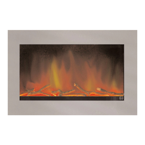
Dru Metro 80E Manual

DRU VERWARMING B.V.
HOLLAND
INSTALLATIE- EN SERVICEHANDLEIDING
INSTALLATION AND SERVICE MANUAL
INSTALLATIONS- UND SERVICEHANDBUCH
MANUEL D’INSTALLATION ET D’ENTRETIEN
Bewaar dit document zorgvuldig
Preserve this document carefully
Bewahren Sie dieses Dokument sorgfältig auf
Conserver minutieusement le présent document
Lees de handleiding in zijn geheel zorgvuldig door
Please read this entire manual carefully
Lesen Sie die Gebrauchsanleitung vollständig und sorgfältig durch
Veuillez lire attentivement tout le manuel
957.647.01
METRO 80E/120E

38E-0022
38E-0023
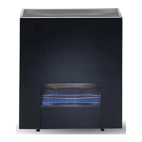
METRO 80E
METRO 120E

Nederlands
Metro 80E/120E
1
INHOUDSOPGAVE
Inhoudsopgave
Woord vooraf...................................................................................2
1. Inleiding.......................................................................................2
2. CE verklaring.............................................................................2
3. Veiligheid.....................................................................................2
3.1. Algemeen.........................................................................2
3.2. Voorschriften ..................................................................2
3.3. Voorzorgsmaatregelen / veiligheidsinstructies bij
installatie .........................................................................2
3.4. Extra bescherming.........................................................3
4. Verpakking..................................................................................3
5. Uitpakken en recycling............................................................3
6. Installatie ....................................................................................3
6.1. Voorschriften ..................................................................3
6.2. Controle vlambeeld.......................................................3
6.3. Controle verwarmingsmodule....................................3
6.4. Plaatsen toestel ..............................................................4
6.5. Monteren fixeerbeugels................................................4
6.6. Plaatsen boezem.............................................................4
7. Plaatsen en verwijderen glasruit ...........................................4
7.1. Verwijderen glasruit.......................................................4
7.2. Plaatsen glasruit..............................................................4
8. Plaatsen blokkenset..................................................................5
8.1. Blokkenset 80E...............................................................5
8.2. Blokkenset 120E.............................................................5
8.3. Kiezelset...........................................................................5
9. Onderhoud................................................................................5
9.1. Algemeen.........................................................................5
9.2. Demonteren van het toestel t.b.v. service ...............5
10. Het monteren van de componenten...................................6
11. Draadloze afstandsbediening .................................................6
12. Oplevering .................................................................................6
13. Storingen....................................................................................7
Figuren ......................................................................................32
Afmetingen toestel 80E.........................................................38
Afmetingen toestel 120E ......................................................39

2
INSTALLATIE- EN SERVICEHANDLEIDING
Woord vooraf
Geachte installateur,
Bij het toestel worden twee handleidingen geleverd:
de installatiehandleiding en de gebruikshandleiding.
De installatiehandleiding geeft u de informatie die u nodig
hebt om het toestel zo te installeren dat het goed en veilig
functioneert. Deze handleiding schenkt aandacht aan de
installatie van het toestel en verwijst u naar de daarvoor
geldende voorschriften. Daarnaast treft u technische ge-
gevens van het toestel aan en informatie over onderhoud,
eventueel optredende storingen en de mogelijke oorzaak
hiervan. U dient deze installatiehandleiding zorg-
vuldig te lezen en te gebruiken alvorens het toestel
te installeren of service te verlenen! In de tekst wordt
verwezen naar afbeeldingen, de afbeeldingen staan achterin
deze installatiehandleiding.
In de handleidingen worden de volgende markeringen ge-
bruikt om belangrijke informatie aan te geven.
→ Uit te voeren acties.
! Tip Suggesties en adviezen.
! Let op Deze instructies zijn noodzakelijk ter
voorkoming van mogelijke problemen bij
gebruik.
Deze instructies zijn noodzakelijk ter
voorkoming van brand, persoonlijk letsel of
andere ernstige schades.
1. Inleiding
Het toestel wordt geleverd in combinatie met een
blokkenset of kiezels.
Het vlameffect van deze sfeerhaard kan gebruikt worden
met en zonder verwarming.
De verwarming kan in twee standen worden gebruikt,
namelijk 750 Watt of 1500 Watt
De energie die verbruikt wordt bij het creëren van het
vlambeeld is bijzonder laag (ongeveer 20 Watt).
Dit DRU toestel is ontworpen om in te bouwen in een
boezem of een schouw.
2. CE verklaring
Hierbij verklaren wij, dat de hierna te noemen elektrische
sfeer haard door haar ontwerp en bouwwijze en in de
door ons in het verkeer gebrachte uitvoering aan de in de
desbetreffende, in EG-Richtlijnen vervatte, fundamentele,
veiligheids- en gezondheidseisen voldoet.
Deze verklaring verliest haar geldigheid als zonder schrif-
telijke toestemming van DRU wijzigingen aan het toestel
worden aangebracht.
Product: Elektrische sfeerhaard
Type: Metro 80E/120E
Van toepassing zijn de EG-richtlijnen:
2006/95/EC
89/336/EC
Toegepaste geharmoniseerde normen:
IEC 60335-1
IEC 60335-2-30
EN 55014-1
EN 55014-2
EN 61000-3-2
EN 61000-3-3
Door bedrijfsinterne maatregelen is gewaarborgd dat serie-
matig geproduceerde apparatuur altijd aan de eisen van de
van kracht zijnde EG-richtlijnen en de toegepaste normen
voldoet.
R. Gelten
Dru verwarming B.V.
Postbus 1021, 6920 BA Duiven
Ratio 8, 6921 RW Duiven
Tel. +31 26 3195319
Fax. +31 26 3195300
www.dru.nl
3. Veiligheid
3.1 Algemeen
- Leest u dit hoofdstuk over veiligheid
zorgvuldig door voordat u begint met
installatie of onderhoud.
- Houdt u zich aan de algemeen geldende voor
schriften en de voorzorgsmaatregelen/
veiligheidsinstructies in deze handleiding.
3.2 Voorschriften
Installeer het toestel volgend de geldende nationale, lokale
en bouwkundige (installatie)voorschriften.
3.3 Voorzorgsmaatregelen / veiligheidsinstructies
bij installatie
Volg de onderstaande voorzorgsmaatregelen/veiligheids-
voorschriften nauwkeurig op:
Het verdient aanbeveling het toestel door een erkende
installateur te laten installeren volgens geldende voor-
schriften.
Aan de onder- en achterzijde van het toestel steken
parkers uit, u kunt zich hieraan verwonden. Wees hier
op bedacht bij het tillen en verplaatsen van het toestel.
Aan de achterzijde van het toestel bevindt zich aan de
bovenkant een schuin uitstekende zetting, u kunt zich
Service mag alleen geschieden door de installateur!

Nederlands
Metro 80E/120E
3
INSTALLATIE- EN SERVICEHANDLEIDING
hieraan verwonden.Wees hierop bedacht bij het tillen en
verplaatsen van het toestel.
De base (figuur 21) mag uitsluitend verwijderd worden
door gekwalificeerd personeel!
Breng geen wijzigingen aan het toestel aan.
Gebruik uitsluitend de meegeleverde blokkenset.
Laat een gescheurde of gebroken ruit vervangen door
uw installateur.
Voor alle onderhoud en service werkzaamheden moet
de stekker uit de contactdoos genomen worden
(figuur 1).
Raadpleeg als het toestel beschadigd is direct de leveran-
cier voordat het toestel wordt geïnstalleerd en voordat
het apparaat in bedrijf wordt genomen.
Gebruik het toestel niet buiten.
Plaats het toestel niet in een vochtige omgeving of nabij
een bad, douche of zwembad.
De uitlaat van de warme lucht en de inlaat voor de
koude lucht mogen op geen enkele wijze geheel of ge-
deeltelijk worden geblokkeerd (zie figuur 2).
Het toestel is geschikt voor 230V, 50Hz en heeft een
aansluitwaarde van maximaal 1500 Watt bij 230V.
De stekker moet na installatie altijd bereikbaar zijn.
De wandcontactdoos waarop het toestel wordt aange-
sloten dient geaard te zijn (zie figuur 1).
Plaats geen dingen voor het toestel omdat deze door
warmte aangetast zou kunnen worden (zie figuur 2).
Leg het netsnoer nooit in de buurt van de hete lucht
uitlaat.
Laat geen kinderen of hulpbehoevende personen zonder
toezicht in de buurt van het toestel en houd de
afstandsbediening buiten bereik van kinderen en hulp-
behoevenden.
Gebruik dit toestel niet in combinatie met andere rege-
lapparatuur zoals een timer, thermische regelaar of een
geprogrammeerde controller wat ervoor zorgt dat het
toestel automatisch inschakelt. Het toestel zou bedekt
kunnen zijn of iemand zou iets onder of voor het toestel
geplaatst kunnen hebben, wat zou kunnen leiden tot
brand.
In geval van storing de stekker uit de wandcontactdoos
nemen.
Natte kleding, handdoeken e.d. niet op of nabij het
toestel te drogen hangen.
Door het toestel met de afstandsbediening op stand-by
te zetten blijft er een kleine stroom door het toestel
lopen, het verdient de aanbeveling voor het uitschakelen
de aan/uit schakelaar te gebruiken.
Het toestel NIET gebruiken bij omgevingstemperaturen
lager dan 2ºC en hoger dan 40ºC.
Het toestel NIET gebruiken als de luchtvochtigheid meer
dan 80% bedraagt.
Het toestel NIET gebruiken boven de 2000 meter.
Let op: Het toestel weegt ongeveer 50 kg, verplaats
het toestel niet zonder hulp van een tweede persoon.
3.4 Extra bescherming
Indien het toestel in een vertrek geïnstalleerd
wordt waar jonge kinderen of hulpbehoevende
mensen zonder toezicht verblijven, adviseren
wij het toestel af te schermen en de afstandsbedie-
ning op een veilige plek op te bergen.
4. Verpakking
Het toestel mag alleen getransporteerd worden in de daar-
voor bedoelde verpakking. Door geen gebruik te maken
van de juiste verpakking kan er transportschade ontstaan
waardoor gevaarlijke situaties kunnen ontstaan.
5. Uitpakken en recycling
Bij ontvangst moet gecontroleerd worden of de verpak-
king onbeschadigd is. Is dit niet het geval dan dient u
contact op te nemen met uw leverancier. Gebruik het
artikel bij beschadigde verpakking in geen geval!
Controleer het toestel op transportschade. Neem bij
elke vorm van schade contact op met uw leverancier en
gebruik het toestel in geen geval!
Bewaar de verpakking tot het toestel geïnstalleerd is en
de goede werking is getest.
De verpakking dient via de regulier weg afgevoerd te
worden.
6. Installatie
Lees de handleiding zorgvuldig door voor een goede en
veilige werking van het toestel.
Installeer het toestel in de volgorde zoals in dit hoofdstuk
is beschreven.
6.1 Voorschriften
- Houdt u zich aan de geldende (installatie)voorschriften.
- Houdt u zich aan de voorschriften/instructies zoals
vermeld in deze handleiding.
6.2 Controle vlambeeld
- Plaats het bijgeleverde netsnoer in de wandcontactdoos.
- Zet het toestel aan door middel van de schakelaar links
bovenin het toestel.
- Controleer of het vlambeeld zichtbaar wordt.
- Gebruik de afstandsbediening om te controleren of de
intensiteit van het vlambeeld gereguleerd kan worden
(zie hoofdstuk 11- Afstandsbediening).
6.3 Controle verwarmingsmodule
In de verwarmingelementen is een thermische beveiliging
opgenomen om oververhitting te voorkomen, deze kan de
verwarming uitschakelen als de uitlaat voor warme lucht
wordt belemmerd (zie figuur 2). Na afkoeling zal het ver-
warmingselement vanzelf weer inschakelen. Mocht deze
beveiliging om wat voor een reden dan ook zomaar inscha-
kelen, dan dient u contact op te nemen met uw leverancier.

4
INSTALLATIE- EN SERVICEHANDLEIDING
Nadat het verwarmingselement wordt uitgeschakeld zal
de ventilator nog enkele seconden nadraaien met het doel
het element af te koelen. In verband met deze functie is het
van belang dat het verwarmingselement met de afstand-
bediening wordt uitgeschakeld voordat het toestel met de
hoofdschakelaar wordt uitgezet. De hoofdschakelaar mag
pas omgezet worden als de ventilator is uitgedraaid, dit zal
ongeveer 30 seconden duren.
- Gebruik de afstandsbediening om het verwarmings-
element aan te zetten
(zie hoofdstuk 11- Afstandsbediening).
- Controleer of er warmte uit het rooster geblazen wordt.
- Controleer of beide warmte standen in en uitgeschakeld
kunnen worden met de afstandsbediening.
6.4 Plaatsen toestel
Het plaatsen van het toestel gebeurt als volgt:
Bepaal de plaats van het toestel.
Zet het toestel op de daarvoor bestemde plek.
Zet het toestel waterpas.
Zorg ervoor dat er een geaarde wandcontactdoos bin-
nen bereik is welke geschikt is om 10 Ampère te kunnen
leveren en dat deze bereikbaar blijft na het plaatsen van
de boezem.
Houd rekening met de diepte van het toestel (275mm).
Laat de ruimte tussen de toestelpoten, boven het
toestel, achter het toestel en voor het toestel vrij
(zie figuur 3).
Dek het toestel niet af en/of pak het niet in met
een isolatiedeken of enig ander materiaal.
Plaats het toestel altijd op minimaal 1
meter afstand van brandbare objecten of
materialen.
Houd rekening met de inbouwhoogte, deze is afhankelijk
van de instelling van de stelvoeten.
6.5 Monteren fixeerbeugels
Om te voorkomen dat het toestel na inbouwen gedurend
schoonmaakwerkzaamheden o.i.d. naar achteren verschuift
of naar voren kan kantelen, worden er twee fixeerbeugels
(zie figuur 4) bijgeleverd.
Deze beugels fixeren de beide achterpoten van het toestel.
Monteer deze beugels met de bijgeleverde spaanplaat-
schroeven.
6.6 Plaatsen boezem
Het toestel is ontworpen om strak in te bouwen in een
nieuw te bouwen boezem. Daarnaast wordt de mogelijk-
heid geboden om tegen deze boezem een sierschouw te
plaatsen.Voor een goede toevoer van koude lucht en afvoer
van de warmte dient er voldoende ruimte rondom het
toestel aanwezig te zijn (zie figuur 2 en 3).
Gebruik van onbrandbaar en hittebestendig materiaal
voor de boezem is aan te raden.
Houd rekening met de minimaal vereiste inwendige
afmetingen van de boezem:
- min. inwendige hoogte: 80E=700mm / 120E=750mm.
- min. inwendige breedte: 80E=1000mm / 120E=1300mm.
- min. inwendige diepte: 80E=275mm / 120E=275mm.
(een grotere diepte is wenselijk, maar niet vereist).
Houd rekening met de inbouwmaten (zie figuur 5):
- breedte inbouwopening: 80E=797mm / 120E=1150mm.
- hoogte inbouwopening: 80E=300mm / 120E=350mm.
De geadviseerde hoogte van onderkant van de
inbouwopening ten opzichte van de begane grond:
minimaal 100 mm en maximaal 1000 mm. Als u de
onderkant van deze inbouwopening binnen deze range
positioneert zal het vlambeeld het beste tot zijn recht
komen. Het is niet toegestaan het toestel hoger te
hangen dan 1800 mm!
LET OP! Als er een sierschouw voor de boezem
geplaatst gaat worden dan zal de inbouwhoogte
door de schouw bepaald worden. U dient zich dan
aan deze maatgeving te houden!
Stuc niet op of over de flenzen (inbouwframe) omdat:
- door de warmte van het toestel scheuren kunnen
ontstaan.
- de glasruit niet meer verwijderd/geplaatst kan worden.
- het stucwerk kan de lak van het toestel aantasten.
Laat bij gebruik van stucwerk de boezem minimaal 6
weken drogen ter voorkoming van scheuren alvorens
het verwarmingselement te gebruiken.
7. Plaatsen en verwijderen glasruit
Voorkom bij het plaatsen en verwijderen van de glasruit
beschadigingen van het toestel en de ruit!
Zorg ervoor dat vóór het verwijderen van de ruit, het
verwarmingselement is uitgeschakeld
(zie hiervoor paragraaf 6.3).
7.1 Verwijderen glasruit
1. Verwijder de sierstrip aan de rechterkant van het toestel
(figuur 6).Verwijder op dezelfde wijze de sierstrip aan
de linkerkant. Let op! Door het verwijderen van de
sierstrippen komt de glasruit los. Houd met één
hand de ruit op zijn plek tijdens het uitvoeren
van stap 2.
2. Verwijder het luchtinlaatprofiel uit het toestel (figuur 7).
3. Kantel de glasruit iets naar voren (figuur 8). Haal de ruit
nu voorzichtig uit het toestel (let op voor beschadi-
gingen aan het inbouwframe!). Leg of zet de glasruit
weg op een veilig plaats waar het niet breken kan.
7.2 Plaatsen glasruit
1. Pak de glasruit met beide handen vast. Breng de glasruit
voorzichtig tussen het inbouwframe door naar binnen
(let op voor beschadigingen aan het inbouw-
frame!).
2. Zet de onderkant van de glasruit op de 2 rubbers die
daarvoor bedoeld zijn.
3. Kantel de glasruit rustig naar achteren tot deze rechtop
in het toestel staat. Hou deze met één hand vast om
hem op zijn plaats te houden.

Nederlands
Metro 80E/120E
5
INSTALLATIE- EN SERVICEHANDLEIDING
4. Plaats het luchtinlaatprofiel in het toestel (figuur 9).
5. Plaats de rechter sierstrip (figuur 10). Plaats op
dezelfde wijze de linker sierstrip.
8. Plaatsen blokkenset
8.1 Blokkenset 80E
Plaats de blokkenset zoals voorgeschreven. Het is van be-
lang dat de blokken op de correcte wijze worden neerge-
legd in verband met het vlambeeld! Zorg dat het toestel in
werking is tijdens het neerleggen van de blokken. Hierdoor
kan namelijk bepaald worden of de blokken nadelig effect
op het vlambeeld hebben!
1. Pak de blokkenset uit en controleer de blokken op
schade. Indien dit het geval is neem dan contact op met
uw leverancier.
2. Verwijder de glasruit (hoofdstuk 7).
3. Plaats blok A aan de linkerkant op de base (figuur 11).
4. Plaats blok D aan de rechterkant op de base verdeel deze
in het midden (figuur 12)
5. Leg blok B op de base over de blokken A en D
(figuur 13)
6. Leg snipper E op de base voor blok A (figuur 14).
7. Indien gewenst kunnen de bijgeleverde chips naar eigen
inzicht als extra decoratie op de base worden
neergelegd.
8. Plaats de glasruit (zie hoofdstuk 7). Controleer na het
plaatsen van de glasruit of het vlambeeld nog altijd
correct weergegeven wordt op de projectieplaat.
8.2 Blokkenset 120E
1. Pak de blokkenset uit en controleer de blokken op
schade. Indien dit het geval is neem dan contact op met
uw leverancier.
2. Verwijder de glasruit (hoofdstuk 7)
3. Plaats blok A aan de linkerkant op de base ongeveer
5 cm vanaf de zijkant (figuur 15)
4. Plaats blok B aan de rechterkant op de base verdeel
deze in het midden ongeveer 5 cm vanaf de zijkant.
(figuur 16)
5. Leg blok C op de base over de blokken A en B
(figuur 17)
6. Leg snipper E op de base voor blok A (figuur 18)
7. Leg blok D tegen blok B aan (figuur 19)
8. Indien gewenst kunnen de bijgeleverde chips naar eigen
inzicht als extra decoratie op de base worden
neergelegd.
9. Plaats de glasruit (zie hoofdstuk 7). Controleer na het
plaatsen van de glasruit of het vlambeeld nog altijd
correct weergegeven wordt op de projectieplaat.
8.3 Kiezelset
Als men gebruikt maakt van de kiezelset kunnen de reflec-
tiestrips, dit zijn aluminiumstrippen die op de achterwand
geplakt zijn, verwijderd worden.
9. Onderhoud
9.1 Algemeen
Uw toestel dient jaarlijks te worden gecontroleerd,
dit dient door een gekwalificeerd bedrijf te gebeuren.
Bij de jaarlijkse controle dient gelet te worden op de
volgende punten:
- Stofvorming in het toestel.
- Stofvorming in de ventilator en het verwarmingselement.
- Kwaliteit van de aardverbinding.
Houd gedurende de uitvoering van het onderhoud
rekening met de volgende punten:
1. Verwijder allereerst de stekker uit de contactdoos.
2. Zorg ervoor dat de elektronica niet beschadigd door
statische elektriciteit.
3. Zorg dat het toestel is afgekoeld en dat het toestel span-
ningsvrij is voordat met het onderhoud begonnen wordt.
4. Alleen de originele parkers mogen worden gebruikt
omdat deze zorgen voor aarding van het toestel.
Bewaar bij demontage alle originele parkers goed.
Ook mogen er geen parkers weggelaten worden bij de
montage omdat er dan geen goede aarding gewaarborgd
is.
Zonodig kan de luchtinlaat en de luchtuitlaat met de stof-
zuiger en een zachte kwast worden gereinigd, zorg ervoor
dat het toestel spanningsloos is voor dat begonnen wordt
met reinigen. Raak de ventilator niet aan met harde delen,
hierdoor kan onbalans ontstaan.
Op de binnenkant van het voorste glasraam kan zich na
verloop van tijd stof ophopen. U kunt het stof verwijderen
met een glasreiniger of een vochtige doek (zie verwijderen
van de ruit, hoofdstuk 7).
Gebruik bij het reinigen van het toestel geen bijtende of
schurende middelen. Lakbeschadigingen, bijvoorbeeld door
het plaatsen van voorwerpen op of tegen het toestel,
vallen buiten de garantie.
Voor het goed uitvoeren van het onderhoud, moet een groot
gedeelte van de onderdelen uit de haard gedemonteerd
worden. Dit dient met grote zorgvuldigheid te gebeuren
om beschadigingen te voorkomen aan elektrische en
mechanische componenten en zichtdelen van de haard.
9.2 Demonteren van het toestel t.b.v. service
Verwijder de sierstrippen, het luchtinlaatprofiel en de
ruit (zie hoofdstuk 7).
Verwijder het blokkenset.
Verwijder de twee parkers die het borgprofiel op zijn
plek houden (figuur 20a).
Neem nu het borgprofiel voorzichtig uit het toestel
(figuur 20b).
De base ligt nu los tussen de zijpanelen, deze kan uitge-
nomen worden (figuur 21).
Verwijder de vier parkers waarmee het rechter zijpaneel
bevestigd zit (figuur 22a). Neem het rechter zijpaneel
uit het toestel (figuur 22b). Doe ditzelfde met het
linker zijpaneel.

6
INSTALLATIE- EN SERVICEHANDLEIDING
LET OP! Het linker zijpaneel draagt de zekeringen.
Deze hoeven niet losgekoppeld te worden, het paneel kan
samen met de zekeringen en bekabeling voorzichtig
uitgenomen worden.
Ontkoppel de vijf elektriciteitskabels zoals weergegeven
in (figuur 23a en 23b).
Verwijder de parkers waarmee de vlammenunit in het
toestel bevestigd zit (figuur 24a). Neem de vlammen-
unit voorzichtig uit het toestel (figuur 24b).
Verwijder de parkers waarmee de achterplaat in het
toestel bevestigd zit (figuur 25a). Neem de achterplaat
voorzichtig uit (figuur 25b)! Beschadigingen hebben
grote invloed op het vlambeeld!
Haal de kabelboom en de IR-kabel voorzichtig los uit de
clips waarin deze bevestigd zit (figuur 26a).Verwijder
de vier parkers waarmee de heaterunit bevestigd zit.
Begin met de twee parkers aan de voorzijde, als laatste
de twee aan de achterzijde (figuur 26b). Zorg dat u met
één hand de heaterunit ondersteunt bij het losdraaien
van de achterste twee parkers zodat u het geheel gecon-
troleerd uit het toestel kunt nemen (figuur 26c).
Verwijder de drie parkers waarmee de verwarmingsset
in de verwarmingsunit geplaatst zit (figuur 27a). U kunt
de verwarmingsset nu los nemen (figuur 27b) en de
bekabeling eventueel ontkoppelen (figuur 27c).
10. Het monteren van de componenten
Positioneer de heaterunit in het toestel. De flens aan
de achterzijde van de heaterunit kan in het toestel
gehaakt worden om het positioneren te
vergemakkelijken (figuur 28). Bevestig de twee parkers
aan de achterkant en aan de voorkant om de heaterunit
vast te zetten.
Plaats de achterplaat in het toestel en bevestig deze met
de vier bijbehorende parkers (figuur 25).
Plaats de vlammenunit in het toestel en bevestig de drie
bijbehorende parkers (figuur 24).
Koppel de vijf elektriciteitskabels aan zoals
weergegeven (figuur 23).
Plaats het linker zijpaneel en bevestig deze in het toestel
met de vier bijbehorende parkers (figuur 22). Doe
ditzelfde met het rechter zijpaneel.
Plaats de base los tussen de zijpanelen in het toestel
(figuur 21). Schuif de base zo ver mogelijk naar achteren.
Positioneer het borgprofiel voorzichtig in het toestel
(figuur 20). Onder in het toestel zijn twee uitsparingen
gemaakt waarin het profiel gepositioneerd dient te
worden. Zorg dat de base vastgeklemd wordt door de
flens die aan het borgprofiel zit. Bevestig de twee
bijbehorende parkers.
Positioneer de blokkenset (zie hoofdstuk 8).
Plaats de ruit en de sierstrippen op de juiste plaats
(zie hoofdstuk 7).
11. Draadloze afstandsbediening
Het toestel wordt standaard geleverd met een draadloze
bediening. Hiermee kunnen de in het toestel aanwezige
verwarmingselementen aan- en uitgezet worden, de lichtin-
tensiteit (hoogte van het vlameffect) kan aangepast worden
en het toestel kan op standby gezet worden.
In (figuur 29) zijn de symbolen op de afstandbediening
verklaard. De elektrische voeding van de afstandsbediening
wordt verzorgd door batterijen. De levensduur van de bat-
terijen is ongeveer één jaar. U moet tijdens bediening van
de afstandsbediening deze richten op het toestel, dit omdat
het gaat om een infrarood afstandsbediening.
De afstandsbediening werkt alleen als de hoofdschakelaar
van het toestel op 1 is gezet.
A Standby
B Vlammen en gloei-effect hoger
(in stappen drukken a.u.b.)
C Verwarmingselement I AAN/UIT
D Verwarmingselement II AAN/UIT
E Vlammen en gloei-effect lager
(in stappen drukken a.u.b.)
F Verwarmingselement I en II uit
12. Oplevering
U dient de gebruiker vertrouwd te maken met het toe-
stel. U dient haar/hem te instrueren over onder meer de
ingebruikname, de werking en de afstandsbediening, het
jaarlijkse onderhoud.
Laat de gebruiker bij storingen/slecht functione-
ren onmiddellijk de stekker uit de contactdoos
halen en contact opnemen met de installateur
ter voorkoming van onveilige situaties.
Laat zien waar de stekker in de contactdoos zal
zitten zodat bij de hiervoor beschreven situatie
onmiddellijk ingegrepen kan worden door de
gebruiker.
Wijs er bij ingebruikname op, dat:
- een boezem met stucwerk minimaal 6 weken
dient te drogen vóórdat gebruik gemaakt kan
worden van het verwarmingselement;
- bij de eerste keer dat gebruik gemaakt zal
worden van het verwarmingselement er
vluchtige componenten uitdampen uit verf,
materialen e.d. en dit een onaangename geur
met zich mee kan brengen;
- bij het uitdampen het verwarmingselement bij
voorkeur op de hoogste stand wordt gezet;
- de ruimte goed wordt geventileerd.
Overhandig de gebruiker de gebruikershand-
leiding én de installatiehandleiding (de hand-
leidingen dienen zorgvuldig bewaard te blijven).

Nederlands
Metro 80E/120E
7
INSTALLATIE- EN SERVICEHANDLEIDING
13. Storingen
Het toestel heeft wel een vlameffect en de venti-
lator doet het, er komt alleen geen warmte lucht
meer uit het toestel.
Mogelijk heeft de thermische beveilig ingegrepen, na
verloop van tijd zal de beveilig afkoelen en er weer warmte
gegenereerd worden.
Mocht de beveiliging direct weer ingrijpen en het verwar-
mingselement uitschakelen, dan dient u uw leverancier te
raadplegen.
Het toestel doet niets meer.
Neem de stekker uit het toestel, en controleer of de beide
zekeringen in de netentree niet defect zijn.
Als de zekeringen defect zijn kunt u nieuwe plaatsen (2 stuks
van 10 AmpereTraag) (zie figuur 30) en de stekker weer
terug plaatsen, als de zekering opnieuw defect raken moet
contact opnemen met uw leverancier.
Plaats onder geen enkele voorwaarde zekeringen van meer
als 10 Ampere. Dit zou bij kortsluiting ernstige gevolgen
kunnen hebben.

8

English
Metro 80E/120E
9
CONTENTS
Contents
Preface .........................................................................................10
1. Introduction.............................................................................10
2. CE declaration ..................................................................... 10
3. Safety.........................................................................................10
3.1. General...........................................................................10
3.2. Regulations ................................................................. 10
3.3. Precautions / safety instructions during
installation .................................................................. 10
3.4. Extra protection...........................................................11
4. Packaging ................................................................................ 11
5. Removing the packaging and recycling ..............................11
6. Installation................................................................................11
6.1. Regulations ....................................................................11
6.2. Checking the flame picture...................................... 11
6.3. Checking the heating module ................................ 11
6.4. Placing the appliance ................................................ 12
6.5. Mounting fastening brackets.................................... 12
6.6. Placing the chimney breast ..................................... 12
7. Placing and removing the glass pane................................ 12
7.1. Removing the glass pane .......................................... 12
7.2. Placing the glass pane ............................................... 12
8. Placing the block set..............................................................13
8.1. Block set 80E ................................................................13
8.2. Block set 120E ........................................................................13
8.3. Pebble set.......................................................................13
9. Maintenance.............................................................................13
9.1. General...........................................................................13
9.2. Disassembling the appliance for service .............. 13
10. Mounting the components...................................................14
11. Wireless remote control......................................................14
12. Delivery....................................................................................14
13. Malfunctions ............................................................................15
Figures .........................................................................................32
Dimensions Appliance 80E......................................................... 38
Dimensions Appliance 120E.........................................................39

10
INSTALLATION AND SERVICE MANUAL
Preface
Two manuals are supplied with the appliance: the installati-
on manual and the user manual.The installation manual will
give you the information you need to install the appliance
in such a way that it will operate properly and safely.This
manual discusses the installation of the appliance and will
refer you to the regulations that apply to the installation. In
addition, you will find technical data for the appliance and
information on maintenance, any malfunctions that might
occur and their possible causes. Carefully read this instal-
lation manual prior to installing or servicing the appliance,
and use the manual while performing the work! In the
text you will find references to pictures.You can find these
pictures in the back of the installation manual.
The following symbols are used in the manual to indicate
important information.
→ Work to be performed.
! Tip Suggestions and recommendations.
! Caution You will need these instructions to prevent
problems that might occur during use.
You will need these instructions to prevent
fire, personal injury or other serious
damages.
1. Introduction
The appliance is supplied together with a block set or
pebbles.
The flame effect of this atmospheric hearth can be used
with and without heating.
The heating can be used in two positions, namely 750 watts
or 1500 watts.
The energy used for creating the flame picture is very low
(about 20 watts).
The DRU appliance is designed to be mounted in a chimney
breast or a mantelpiece.
2. CE declaration
We hereby declare that the design and construction of the
appliance, hereafter referred to as an electric atmospheric
hearth, and the version introduced by us, complies with
the applicable fundamental safety and health requirements
described in EC directives.
This declaration will lose its validity if adjustments are made
to the appliance, without prior written permission by DRU.
Product: electric atmospheric hearth
Type: Metro 80E/120E
Applicable EEC directives
2006/95/EC
89/336/EC
Applied harmonized standards:
IEC 60335-1
IEC 60335-2-30
EN 55014-1
EN 55014-2
EN 61000-3-2
EN 61000-3-3
Internal measures by the company guarantee that equip-
ment produced in series complies with the requirements of
the prevailing EC directives and the standards applied.
R. Gelten
Dru verwarming B.V.
Postbus 1021, 6920 BA Duiven
Ratio 8, 6921 RW Duiven
Tel. +31 26 3195319
Fax. +31 26 3195300
www.dru.nl
3. Safety
3.1 General
- Carefully read this chapter on safety, before you
start performing installation or maintenance
work.
- Please observe the general regulations and the
precautions/safety instructions in this manual.
3.2 Regulations
Please install the appliance in accordance with the
applicable national, local and constructional (installation)
regulations.
3.3 Precautions / safety instructions during
installation
Carefully observe the following precautions/safety
regulations:
We recommend that you use an authorized installer to
install the appliance in accordance with the applicable
regulations.
Self-tapping screws are protruding from the bottom and
back of the appliance, which could cause injuries.
Be aware of this when lifting and moving the appliance.
At the rear of the appliance you will find a slantingly
protruding lower part, this could injure you. Be aware of
this when lifting and moving the appliance.
The base (figure 21) may only be removed by qualified
personnel!
Do not make any changes to the appliance.
Only use the supplied block set.
Service may only be performed by the installer!

English
Metro 80E/120E
11
INSTALLATION AND SERVICE MANUAL
Have a cracked or broken glass pane replaced by your
installer.
When performing maintenance and service work, you
should always remove the power plug from the wall
socket (figure 1).
In case of damages to the appliance, immediately consult
the supplier, before it is installed and put into operation.
Do not use the appliance outdoors.
Do not place the appliance in a moist environment or
near a bath, shower or pool.
The warm air outlet and cold air inlet may never be
completely or partly blocked (see figure 2).
The appliance is suitable for 230V, 50Hz and has a maxi-
mum connecting value of 1500 watts at 230V.
You should always be able to reach the plug after instal-
lation.
The wall socket to which the appliance will be connec-
ted, must be earthed (see figure I).
Do not place any objects in front of the appliance as
they could be affected by the heat (see figure 2).
Never place the power cable near the hot air outlet.
Do not let children or infirm persons near the appliance
without supervision and keep the remote control out of
their reach.
Do not use this appliance in combination with other
control equipment, such as timers, thermal controllers
or programmed controllers, which will automatically
switch on the appliance.The appliance could be covered
or someone may have placed something under or in
front of the appliance, which could result in fire.
In case of a malfunction, remove the plug from the wall
socket.
Do not hang wet clothes, towels etc. on or near the
appliance in order to dry them!
When you use the remote control to put the appliance
in standby mode, a bit of electric current will continue
to pass through the appliance, we recommend use of the
on/off switch to switch off the appliance.
Do NOT use the appliance at room temperatures below
2ºC and above 40ºC.
Do NOT use the appliance when the atmospheric
humidity is higher than 80%.
Do NOT use the appliance at a height above 2,000
metres.
Caution:The appliance weighs approximately 50 kg, do
not try to move the appliance without the assistance of
a second person.
3.4 Extra protection
If the appliance is installed in a room where small
children or infirm people are staying, we recom-
mend screening off the appliance and storing the
remote control in a safe place.
4. Packaging
Het toestel mag alleen getransporteerd worden in de daar-
voor bedoelde verpakking. Door geen gebruik te maken
van de juiste verpakking kan er transportschade ontstaan
waardoor gevaarlijke situaties kunnen ontstaan.
5. Removing the packaging and recycling
When receiving the appliance, you must check if the
packaging is undamaged. If this is not the case, you must
contact your supplier. Never use the product if the pac-
kaging is damaged!
Check the appliance for damages during transport. If
there is any damage at all, contact your supplier and
never use the appliance!
Keep the packaging materials until the appliance is instal-
led and tested.
The packaging must be disposed of in accordance with
regulations.
6. Installation
Read this manual carefully to ensure a proper and safe
operation of the appliance.
Install the appliance in the order described in this chapter.
6.1 Regulations
- Observe the applicable (installation) regulations.
- Observe the regulations/instructions in this manual.
6.2 Checking the flame picture
- Place the supplied power cable in the wall socket.
- Switch on the appliance by using the switch in the left
top of the appliance.
- Check whether the flame picture is visible.
- Use the remote control to check if the intensity of the
flame picture can be regulated
(see chapter 11- Remote control).
6.3 Checking the heating module
A thermal cut-out is incorporated in the heating elements
in order to avoid overheating.This thermal cut-out can
switch off the heating when the hot air outlet is blocked
(see figure 2).When cooled down, the heating element
will switch on again automatically. If the thermal cut-out
is activated with no reason, you should contact your sup-
plier.
After the heating element is switched off, the ventilator will
continue to rotate for a few seconds in order to cool the
element. Because of this feature, it is important that the

12
INSTALLATION AND SERVICE MANUAL
heating element is switched off by means of the remote
control, before the appliance is switched off with the main
switch.The main switch may only be used if the ventila-
tor has finished rotating, this will take approximately 30
seconds.
- Use the remote control to switch on the heating ele-
ment (see chapter 11- Remote control).
- Check whether heat is blown from the grate.
- Check if both heating positions can be switched on and
off using the remote control.
6.4 Placing the appliance
Place the appliance as follows:
Determine the location of the appliance.
Place the appliance on its destined location.
Level the appliance.
Make sure there is an earthed wall socket within reach,
which is able to supply 10 ampere and will still be within
reach after placing the chimney breast.
Take the depth of the appliance into account (275mm).
Leave the space between the appliance legs,
above the appliance, behind the appliance and in
front of the appliance free (see figure 3).
Do not cover the appliance and/or do not wrap it
in an insulation blanket or any other material.
Always place the appliance with a distance of at
least 1 metre from combustible objects or mate-
rials.
Take the build-in height of the appliance into account; it
depends on the setting of the adjustable legs.
6.5 Mounting fastening brackets
To prevent that the appliance can be displaced to the rear
or tilted to the front after construction during cleaning or
something similar, we supply two fastening brackets
(see figure 4).
These brackets fasten both rear legs of the appliance.
Mount these brackets with the supplied chipboard screws.
6.6 Placing the chimney breast
The appliance is designed to be mounted tightly in a new
chimney breast. It is also possible to place a decorative
mantelpiece against this chimney breast. For a proper sup-
ply of cold air and discharge of heat, sufficient space should
be provided around the appliance (see figure 2 and 3).
We recommend using non combustible and heat-re-
sistant materials for the chimney breast.
Comply with the minimum required internal measure-
ments of the chimney breast:
- min. internal height: 80E=700mm / l20E=750mm.
- min. internal width: 80E=l000mm / l20E=l300mm.
- min. internal depth: 80E=275mm / l20E=275mm.
(a greater depth would be better, but is not necessary).
take the construction measurements into account
(see figure 5):
- width construction opening: 80E=797mm /
l20E=ll50mm.
- height construction opening: 80E=300mm /
l20E=350mm.
The recommended height of the bottom side of the con-
struction in relation to ground level. minimum l00 mm and
maximum l000 mm. If you position the bottom side of this
construction opening within this range, the flame picture
will be at its best. It is not allowed to suspend the appli-
ance any higher than 1800 mm!
CAUTION! If a decorative mantelpiece will be
placed in front of the chimney breast, the construc-
tion height will be determined by the mantelpiece.
You must observe these dimensions!
Do not apply plaster on or over the flanges (construc-
tion frame), because:
- the heat of the appliance could cause cracks.
- it will no longer be possible to remove/place the glass
pane.
- the plaster could damage the paint of the appliance.
When using plastern alvorens het verwarmingselement
te gebruiken.
7. Placing and removing the glass pane
When placing and removing the glass pane, avoid damages
to the appliance and/or glass pane.
Prior to removing the glass pane, make sure the heating
element is switched off (for this, see section 6.3).
7.1 Removing the glass pane
1. Remove the decorative strip at the right side of the
appliance (figure 6). Remove the decorative strip at the
left side in the same way. Caution! By removing the
decorative strips, the glass pane will come loose.
Use one hand to keep the glass pane in its place,
while performing step 2.
2. Remove the air inlet profile from the appliance
(figure 7).
3. Tilt the glass pane somewhat to the front (figure 8).
Now, carefully remove the glass pane from the appliance
(beware of damage to the construction frame!).
Lay or place the glass pane on a safe place where it
cannot be broken.
7.2 Placing the glass pane
1. Grab the glass pane with both hands. Carefully insert the
glass pane between the construction frame (beware of
damage to the construction frame!).
2. Place the bottom side of the glass pane on the 2 rubbers
provided for this.
3. Carefully tilt the glass pane backwards, until it is standing
straight in the appliance. Hold it with one hand to keep it
in its place.
4. Place the air inlet profile in the appliance (figure 9).
5. Place the right decorative strip (figure 10). Place the left
decorative strip in the same way.

English
Metro 80E/120E
13
INSTALLATION AND SERVICE MANUAL
8. Placing the block set
8.1 Block set 80E
Place the block set as prescribed. It is important that the
blocks are placed in the correct way, because of the flame
picture! Make sure the appliance is operating while placing
the blocks. In this way you can see whether the blocks have
an adverse effect on the flame picture!
1. Remove the block set from the packaging and check the
blocks for damage. If this is the case, please contact your
supplier.
2. Remove the glass pane (chapter 7).
3. Place block A at the left side, on the base (figure 11).
4. Place block D at the right side on the base, place it in the
middle (figure 12)
5. Place block B on the base over blocks A and D
(figure 13)
6. Place snippet E on the base in front of block A
(figure 14).
7. If required, the supplied chips can be placed on the base
as additional decoration, according to your own taste.
8. Place the glass pane (see chapter 7).After placing the
glass pane, check if the flame picture is still displayed cor-
rectly on the projection plate.
8.2 Block set 120E
1. Remove the block set from the packaging and check the
blocks for damage. If this is the case, please contact your
supplier.
2. Remove the glass pane (chapter 7)
3. Place block A at the left side on the base, approximately
5 cm from the side (figure 15)
4. Place block B at the right side on the base, place it in the
middle, approximately 5 cm from the side. (figure 16)
5. Place block C on the base over blocks A and B
(figure 17)
6. Place snippet E on the base in front of block A
(figure 18)
7. Place block D against block B (figure 19)
8. If required, the supplied chips can be placed on the base
as additional decoration, according to your own taste.
9. Place the glass pane (see chapter 7).After placing the
glass pane, check if the flame picture is still displayed cor-
rectly on the projection plate.
8.3 Pebble set
If you use the pebble set, you can remove the reflection
strips.These are aluminium strips glued against the back
wall.
9. Maintenance
9.1 General
Your appliance must be tested annually,This should be done
by a qualified company.At the annual check, you must pay
attention to the following:
- Accumulation of dust in the appliance.
- Accumulation of dust in the ventilator and the heating
element.
- Quality of the earth connection.
When performing maintenance, take the following into
account:
1. First, remove the plug from the wall socket.
2. Make sure the electronics are not damaged as a result of
static electricity.
3. Make sure the appliance is cooled down and dead before
you start maintenance.
4. Only the original self-tapping screws may be used, as
they provide the appliance’s earth.When disassembling,
carefully store the original self-tapping screws. No self-
tapping screws may be left out when reassembling, as a
good earthing will not be guaranteed in this way.
If necessary, the air inlet and air outlet can be cleaned with
a vacuum cleaner and a soft brush. Make sure the appliance
is dead before you start cleaning it. Do not touch the venti-
lator with hard objects, this may cause imbalance.
On the inside of the front glass pane dust may accumu-
late after some time.You can remove the dust with a glass
cleaner or a moist cloth (see Removing the glass pane,
chapter 7).
Do not use corrosive or abrasive agents when cleaning the
appliance. Damages to the paint, for example as a result of
placing objects on or against the appliance, are not covered
by the warranty.
In order to be able to perform maintenance properly,
many parts will have to be disassembled from the hearth.
This should be done with great care, to avoid damages to
electrical and mechanical components and visible parts of
the hearth
9.2 Disassembling the appliance for service
Remove the decorative strips, the air inlet profile and
the glass pane (see chapter 7).
Remove the block set.
Remove the two self-tapping screws that keep the lock
profile in its place (figure 20a).
The base is now loose between the side panels, and can
be removed (figure 21).
Remove the four self-tapping screws fixing the right side
panel (figure 22a). Remove the right side panel from
the appliance (figure 22b). Do the same for the left side
panel.
Now carefully remove the lock profile from the appli-
ance (figure 20b).

14
INSTALLATION AND SERVICE MANUAL
CAUTION! The left side panel carries the fuses.They do
not have to be disconnected,The panel plus the fuses and
cables can be removed carefully.
Disconnect the five electricity cables as indicated in
(figure 23a and 23b).
Remove the self-tapping screws that fix the flame unit in
the appliance (figure 24a). Carefully remove the flame
unit from the appliance (figure 24b).
Remove the self-tapping screws that fix the rear plate in
the appliance (figure 25a). Carefully remove the rear
plate from the appliance (figure 25b)! Damages gre-
atly affect the flame picture!
Carefully remove the cable tree and the IR-cable from
the clips that fix it (figure 26a). Remove the four self-
tapping screws fixing the heater unit. Start with two
self-tapping screws at the front, finishing with the last
two at the rear (figure 26b). Make sure you support
the heater unit with one hand when loosening the rear
two self-tapping screws, so you can carefully remove the
whole unit from the appliance (figure 26c).
Remove the three self-tapping screws placing the heating
set in the heating unit (figure 27a).You can now dis-
connect the heating set (figure 27b) and, if necessary,
disconnect the cabling (figure 27c).
10. Mounting the components
Position the heater unit in the appliance.The flange at
the rear of the heater unit can be hooked in the appli-
ance to make positioning easier (figure 28).Attach the
two self-tapping screws at the rear and front to fix the
heater unit.
Place the rear plate in the appliance and fix it with the
two respective self-tapping screws (figure 25).
Place the flame unit in the appliance and fix the three
respective self-tapping screws (figure 24).
Connect the five electricity cables as indicated
(figure 23).
Place the left side panel and fix it in the appliance using
the four respective self-tapping screws (figure 22).
Do the same for the right side panel.
Place the base loose between the side panels in the ap-
pliance (figure 21). Slide the base as far to the rear as
possible.
Carefully position the lock profile in the appliance
(figure 20). Under the appliance you will find two reces-
ses, in which the profile should be positioned. Make sure
the base is clamped by the flange attached to the lock
profile.Attach the two accompanying self-tapping screws.
Position the block set (see chapter 8).
Place the glass pane and the decorative strips at the right
location (see chapter 7).
11. Wireless remote control
The appliance is supplied with a wireless control as
standardThis remote control can be used to switch the
heating elements in the appliance on and off, to adjust the
light intensity (level of the flame effect) and to switch the
appliance to standby mode. In figure 29 you will find a des-
cription of the symbols on the remote control.The remote
control is powered by batteries.The batteries will have
an average life of one year.When using the remote con-
trol, you should aim it at the appliance, as it is an infrared
remote control.The remote control will only work, if the
main switch of the appliance is set to position 1.
A Standby
B Higher flames and glow effect (steps by pressing)
C Heating element I ON / OFF
D Heating element II -ON I OFF
E Lower flames and glow effect (steps by pressing)
F Heating elements I and II off
12. Delivery
You must explain to the user how he should operate the
appliance.You should instruct her/him for instance on using
the appliance for the first time, the operation of the remote
control, annual maintenance.
Tell the user to remove the plug from the wall
socket immediately in case of malfunctions/bad
performance and contact the installer in order to
prevent dangerous situations.
Show him where the plug will be in the wall soc-
ket, so the user can act immediately in case of a
situation as described above.
When the appliance is started for the first time,
point out that:
- a chimney breast with plaster should dry at
least 6 weeks prior to using the heating
element;
- if the heating element is used for the first time,
it may be that volatile components evaporate
from paint, materials, etc., and that this my lead
to an unpleasant smell;
- when evaporating, the heating element should
preferably be set at the highest level;
- the room should be well ventilated.
Give the manual AND the installation manual to
the user (the manuals should be stored carefully).

English
Metro 80E/120E
15
INSTALLATION AND SERVICE MANUAL
13. Malfunctions
The appliance does have a flame effect and the
ventilator is working, but there is no more hot air
coming from the appliance.
Maybe the thermal cut-out has been activated.After some
time the thermal cut-out will have cooled down, after
which the appliance will start generating heat again.
If the thermal cut-out is activated again straight away and
switches off the heating element, you should consult your
supplier.
The appliance has stopped working altogether.
Remove the plug from the appliance and check if both fuses
in the mains entrance have not blown.
If the fuses have blown, you can place new ones (two of 10
ampere Slow Blow) (see figure 30) and place back the
plug. If the fuses blow again, you must contact your supplier.
Under no circumstances use fuses of more than 10 ampere.
This would have serious consequences in case of a short
circuit.

16

Deutsch
Metro 80E/120E
17
INHALT
Inhalt
Vorwort............................................................................................18
1. Einleitung..................................................................................18
2. CE-Erklärung............................................................................18
3. Sicherheit..................................................................................18
3.1. Allgemeines....................................................................18
3.2. Vorschriften...................................................................18
3.3. Schutzmaßnahmen/Sicherheitsanweisungen bei
der Installation..............................................................18
3.4. Zusätzliche Schutzmaßnahmen.................................19
4. Verpackung...............................................................................19
5. Auspacken und Recycling......................................................19
6. Installation................................................................................19
6.1. Vorschriften...................................................................19
6.2. Kontrolle des Flammenbilds.......................................19
6.3. Kontrolle des Heizungsmoduls..................................20
6.4. Aufstellen des Geräts..................................................20
6.5. Montieren der Fixierbügel..........................................20
6.6. Aufbau de Kaminumbaus............................................20
7. Einsetzen und Ausbauen der Glasscheibe.........................20
7.1. Ausbau der Glasscheibe..............................................20
7.2. Einsetzen der Glasscheibe.............................................21
8. Positionieren des Holzblock-Sets.......................................21
8.1. Holzblock-Set 80E........................................................21
8.2. Holzblock-Set 120E.....................................................21
8.3. Kiesel-Set.......................................................................21
9. Wartung....................................................................................21
9.1. Allgemeines....................................................................21
9.2. Demontieren des Geräts für Servicearbeiten.......22
10. Montieren der Komponenten..............................................22
11. Drahtlose Fernbedienung.....................................................22
12. Übergabe..................................................................................23
13. Störungen.................................................................................23
Abbildungen.............................................................................32
Abmessungen Modell 80E.....................................................38
Abmessungen Modell 120E..................................................39

18
INSTALLATIONS- UND SERVICEANLEITUNG
Vorwort
Sehr geehrter Installateur,
Gemeinsam mit dem Gerät werden zwei Handbücher gelie-
fert: die Installationsanleitung und die Bedienungsanleitung.
Die Installationsanleitung enthält die Informationen, die Sie
benötigen, um das Gerät so zu installieren, dass es einwand-
frei und sicher funktioniert. Diese Anleitung befasst sich mit
der Installation des Geräts und verweist auf die dafür gel-
tendenVorschriften. Darüber hinaus enthält diese Anleitung
die technischen Daten des Geräts sowie Informationen zur
Wartung, zu eventuell auftretenden Störungen sowie zu
der/den möglichen Ursache(n). Sie müssen diese Instal-
lationsanleitung sorgfältig lesen und verwenden,
bevor Sie das Gerät installieren oder Servicearbei-
ten ausführen!
In den Anleitungen sind wichtige Informationen mit den
folgenden Symbolen gekennzeichnet:
→ Erforderliche Maßnahmen.
!Tipp Vorschläge und Hinweise.
! Achtung Diese Anweisungen sind erforderlich, um
eventuellen Problemen während des
Gebrauchs vorzubeugen.
Diese Anweisungen dienen zumVerhindern
von Bränden,Verletzungen oder anderen
schweren Schäden.
1. Einleitung
Das Gerät wird mit einem Holzblock-Set oder einem
Kiesel-Set geliefert.
Der Flammenbildeffekt dieses Kaminofens kann mit und
ohne Heizung verwendet werden.
Die Heizung kann in zwei Positionen verwendet werden,
und zwar mit 750 Watt oder 1500 Watt.
Die Energie, die beim Erzeugen des Flammenbilds
verbraucht wird, ist besonders gering (ungefähr 20 Watt).
Dieses DRU-Gerät wurde für den Einbau in einen
Kaminumbau oder einen Kaminsims entworfen.
2. CE-Erklärung
Hiermit erklären wir, dass der im Folgenden beschriebene
elektrische Kaminofen durch seinen Entwurf und seine
Bauweise sowie in der von uns in den Handel gebrachten
Ausführung die in den betreffenden in EG-Richtlinien ver-
fassten, grundlegenden Sicherheits- und Gesundheitsanfor-
derungen erfüllt.
Diese Erklärung verliert ihre Gültigkeit, wenn ohne vorhe-
rige schriftliche Genehmigung von DRU Änderungen am
Gerät gleich welcher Art vorgenommen werden.
Produkt: Elektrischer Kaminofen
Typ: Metro 80E/120E
Gültige EG-Richtlinien:
2006/95/EC
89/336/EC
Angewandte harmonisierte Normen:
IEC 60335-1
IEC 60335-2-30
EN 55014-1
EN 55014-2
EN 61000-3-2
EN 61000-3-3
Durch entsprechende betriebsinterne Maßnahmen ist
sichergestellt, dass serienmäßig hergestellte Geräte immer
die Anforderungen der geltenden EG-Richtlinien sowie die
angewandten Normen erfüllen.
R. Gelten
Dru verwarming B.V.
Postbus 1021, 6920 BA Duiven (Niederlande)
Ratio 8, 6921 RW Duiven (Niederlande)
Tel. +31 26 3195319
Fax. +31 26 3195300
www.dru.nl
3. Sicherheit
3.1 Allgemeines
- Lesen Sie vor Beginn der Installations- oderWar-
tungsarbeiten dieses Kapitel über die Sicherheit
sorgfältig durch.
- Halten Sie die allgemein gültigenVorschriften sowie
die in dieser Anleitung enthaltenen Schutzmaßnah-
men/Sicherheitsanweisungen unbedingt ein.
3.2 Vorschriften
Installieren Sie das Gerät gemäß den gültigen nationalen,
lokalen und bautechnischen (Installations-)Vorschriften.
3.3 Schutzmaßnahmen/Sicherheitsanweisungen
bei der Installation
Die nachstehenden Schutzmaßnahmen und Sicherheitsvor-
schriften sind genau einzuhalten:
Es wird empfohlen, das Gerät durch einen anerkannten
Installateur unter Einhaltung der geltendenVor-schriften
installieren zu lassen.
Servicearbeiten dürfen nur von einem Installateur ausgeführt werden!
Other manuals for Metro 80E
3
This manual suits for next models
1
Table of contents
Languages:
Other Dru Heater manuals