Woord vooraf
Geachte klant,
Vriendelijk bedankt voor de aankoop van dit DRU
product. Onze producten zijn ontwikkeld en gefabriceerd
volgens de hoogst mogelijke kwaliteits-, prestatie- en
veiligheidseisen. Hierdoor kunt u rekenen op jarenlang
probleemloos gebruiksplezier.
In dit boekje vindt u instructies voor installatie en gebruik
van uw nieuwe toestel. Lees de instructies en gebruikers-
handleiding goed door, zodat u zich vertrouwd maakt met
het toestel. Wilt u meer ondersteuning, neem dan contact
op met uw leverancier.
Uitpakken
Wanneer u klaar bent met uitpakken, dient de verpakking
via de reguliere weg te worden afgevoerd.
Aansluiten
Dit toestel dient te worden aangesloten door een bevoegd
installateur.
INSTALLATIEVOORSCHRIFT
Gassoort
Dit toestel is bestemd voor het land en geschikt voor de
gassoort dat is vermeld op de typeplaat. Controleer of de
gassoort en de gasdruk ter plaatse overeenkomen met de
vermelding op het typeplaatje. Houdt u aan de gasinstal-
latievoorschriften en eventuele plaatselijke voorschriften.
Het toestel dient door een bevoegd installateur te worden
aangesloten.
Om het toestel te laten werken op butaan of propaan
dient het omgebouwd te worden door een bevoegd instal-
lateur. Een ombouwset is via hem te bestellen.
Belangrijk
• Zorg ervoor dat evt. overgordijnen of andere brandbare
materialen minstens 50 cm van het toestel verwijderd zijn.
• Let op! Aanraking van hete delen kan brandblaren veroor-
zaken!
• Het toestel dient door een erkend installateur
geïnstalleerd te worden.
• Het plaatsen van een z.g. stoffilter op of onder de mantel
is niet toegestaan.
• Natte kleding, handdoeken e.d. niet op de kachel te
drogen hangen!
Algemeen
Het toestel kan zowel aan een wand van onbrandbaar
materiaal (b.v. steen of beton), als aan een wand van
brandbaar materiaal (b.v. hout) geïnstalleerd worden.
Installatie aan een wand van onbrandbaar
materiaal (fig. 1)
Het toestel kan hangend of staand worden geïnstalleerd.
Houd er rekening mee dat boven het toestel minimaal 1
meter vrij ruimte nodig is voor voldoende warmteafvoer.
Als u het toestel zo laag mogelijk wilt installeren moet
de afstand van het hart van de muurdoorvoer tot aan de
vloer maat F zijn.
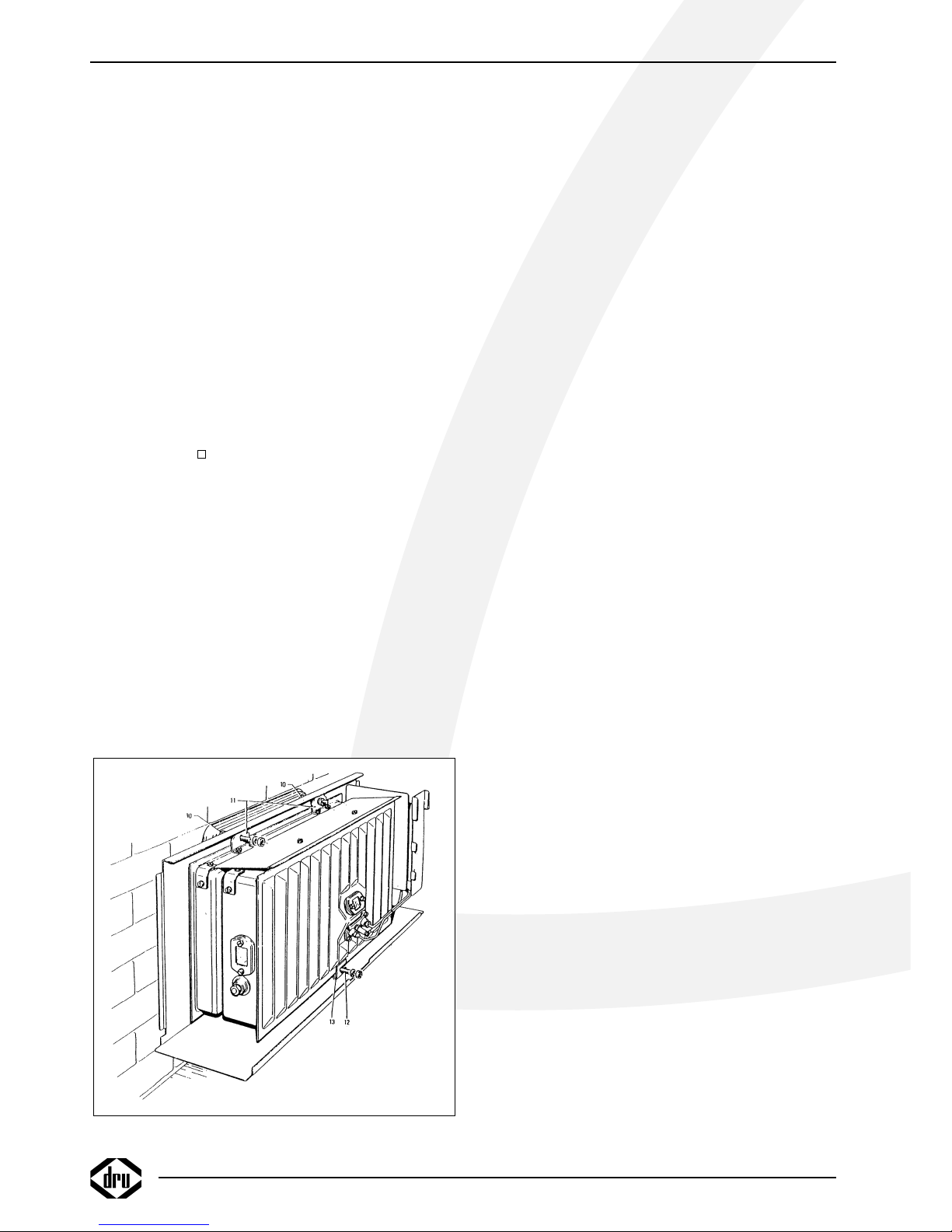
Voor het aftekenen van de muurdoorvoering kan de mon-
tageplaat (2) als mal worden gebruikt. Om de mantel om
het binnenwerk te kunnen hangen moet men rekening
houden dat tussen een eventuele vensterbank en het toe-
stel een vrije ruimte van minimaal 25 mm noodzakelijk is.
De minimum benodigde vrije installatie hoogte bedraagt
maat Y (tabel 1, blz. 3).
De standaard geveldoorvoer
Maak een horizontaal gat in de muur met een diameter
van ø 230mm (maat E) voor doorvoering van de inlaat-
pijp. Zorg er voor dat de muurdoorvoer ongeveer 2º op
afschot ligt.
De standaard geveldoorvoer is geschikt voor wanddiktes
van 50-330 mm en de standaard verlengde doorvoer voor
wanddiktes van 50-600 mm. Afhankelijk van de wanddikte
dienen de in- en uitlaatpijp op lengte te worden gemaakt n.l.
• lengte inlaatpijp = wanddikte + 20 mm.
• lengte uitlaatpijp = wanddikte + 70 mm.
De aan het muurrooster gemonteerde trekstangen kunnen
na montage van de geveldoorvoer worden ingekort.
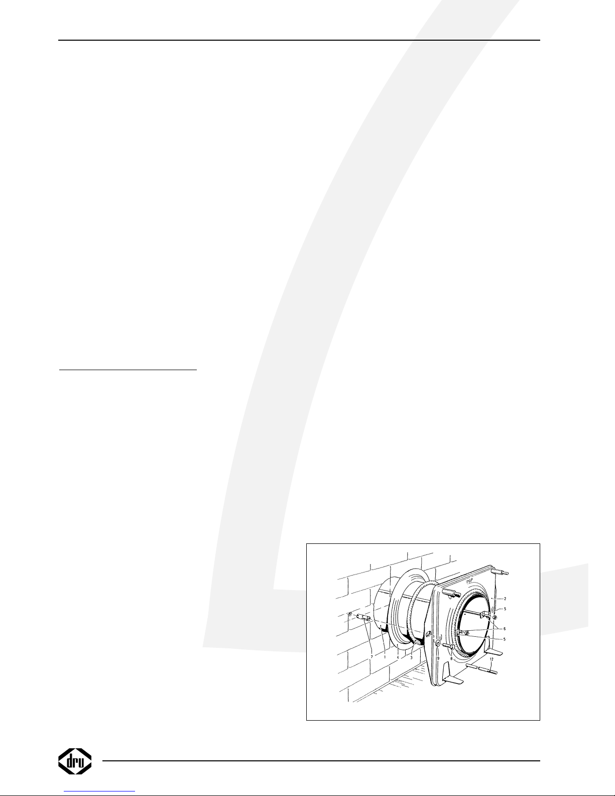
Installatie van de standaard geveldoorvoer
(fig. 3)
Schuif de op lengte gemaakte inlaatpijp (1) door de
montageplaat (2) en zorg daarbij dat de felsnaad tegenover
het merkteken (45˚ links boven) in de montageplaat zit.
Schuif de afdichtring (3) en de muurring (4) om de inlaat-
pijp en let daarbij op de volgorde. (zie figuur). Neem het
geheel en schuif de inlaatpijp in de muuropening. De
INSTALLATIE VOORSCHRIFT
2
fig. 3