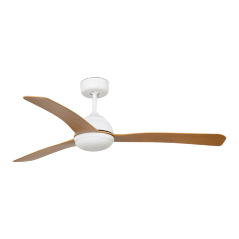
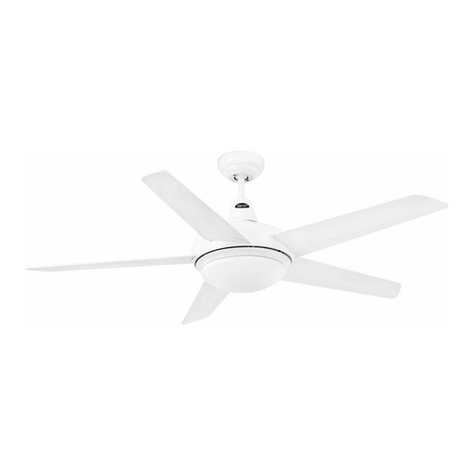
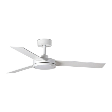
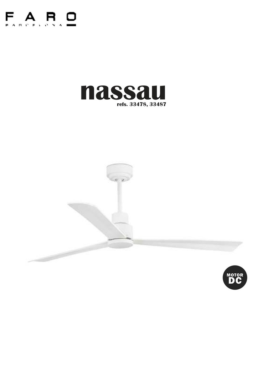
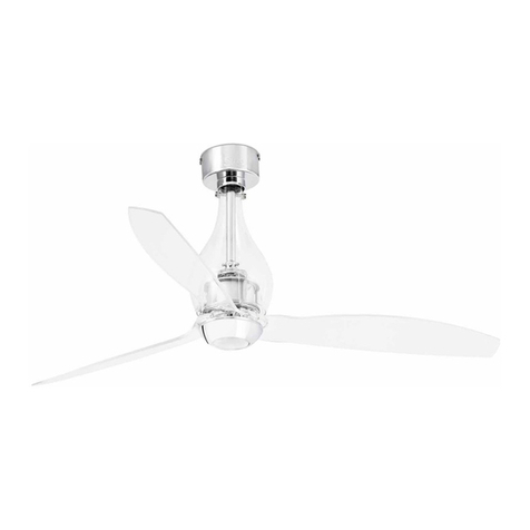
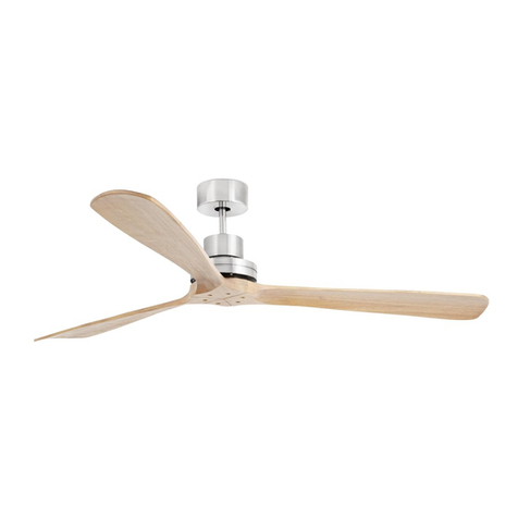
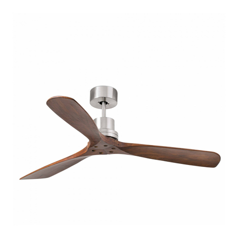
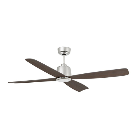
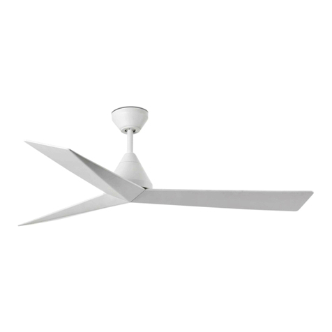
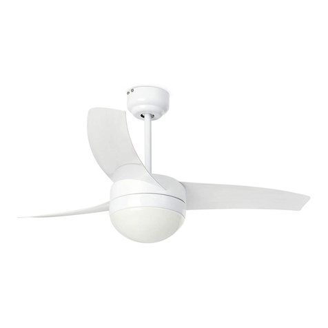
Faro mini eterfan User manual


IMPORTANT!

Do not connect the fan directly to the power source. A wall controller is not available for this
fan. Only use the remote control provided with the product. Contact the distributor if you
need to replace the product.
1- Protection class I: The fitting has an earthing connection: The earth wire (yellow / green)
has to be connected to the clip marked with .
2- This fitting should only be installed in rooms where direct contact with water is
impossible.
3- Reverse function.
4- Consumption in W, according to the speed of the motor.
5- Revolutions per minute.
6- Remote control, included.
7- This device children can use it with age of 8 years or more and people with physial,
sensory or mental small capacities, if they has been given them the supervision or adapted
training. The children must not play with the fans. The cleanliness and the maintenance
must be done by an adult.
WARNINGS
Read entire booklet carefully before beginning installation and save these instructions. To
reduce the risk of personal injury, attach the fan directly to the support structure of the
building according to these instructions, and use only the hardware supplied.
To avoid possible electrical shock, before installing your fan, disconnect the power by
turning off the circuit breakers to the outlet box and associated wall switch location.
For the electrical connection it is necessary to incorporate an isolator switch according to the
installation regulations, which ensures all-pole cut, directly connected to the power
terminals and it must have a contact separation in all its poles, which provides total
disconnection under category III surge conditions.
All wiring and connections must be made in accordance with national and local electrical
codes. If you are not familiar with the way to do the electrical installation, you must use the
services of a qualified electrician.
Make sure that the fan is disconnected from the mains before removing the protection. To
reduce the risk of personal injury, do not bend the blade attachment the system when
installing, balancing or cleaning the fan. Never insert foreign objects between rotating fan
blades.
To reduce the risk of fire, electrical shock or motor damage, do not lift or carry the fan by the
lead wires.
The fan blades cannot be installed lower than 2,3m from the floor.
The important precautions, safeguards and instructions appearing in this manual are not
meant to cover all possible conditions and situations that may occur. It must be understood
that common sense, caution and carefulness are factors which cannot be built into this
product. These factors must be supplied by the person(s) installing, caring for and operating
the unit.

Verify you have all parts before beginning the installation. Check foam insert closely for
missing parts. Remove motor from packing. To avoid damage to finish, assemble motor on
soft padded surface or use the original foam inset in motor box. Do not lay fan on its side as
this could result in shifting of motor in decorative enclosure.

Mini Eter fan / Eter fan
Remove the drop rod. Insert the pin and clevis.
Pass the wires through the post.
Tighten the screw holding the pin in place.

Assemble the glass and the cano- py.
Reinsert the ball and pin.
Make the hanger bracket installation.
Ensure the screws are securely fastened
to the ceiling. Place the fan.

Important:
Fan can only be operated by the supplied
remote. This fan can not work with a controller
wall
Ensure that the connections are correct. If in
doubt consult a technician.

Just fan
Make the hanger bracket installation. Ensure the screws are securely fastened to the ceiling.
Place the fan.

Important:
Fan can only be operated by the supplied remote. This
fan can not work with a controller wall
Make the hanger bracket installation. Ensure the
screws are securely fastened to the ceiling. Place the
fan.
Ensure that the connections are correct. If in doubt
consult a technician.


The reversing switch for hot or cold weather depends on factors such as the size of the
room, height of the ceiling, number of ceiling fans, etc.
Hot weather/downward –The fan will turn in a counter clockwise direction. A downward air
circulation creates a cooling.
This allows you to regulate the air conditioner to a higher temperature without affecting
your comfort.
Cold weather/upward –The fan will turn in a clockwise direction. An upward air circulation
will distribute the warmer air trapped at the ceiling around the room without causing a
draft. This allows you to regulate the heating to a lower temperature without affecting your
comfort.
NOTE: To change the direction of air flow, turn the fan off and let it come to a complete
stop.
MAINTENANCE
1. As fans tend to move during operation, some connections may loosen. Check the
supporting screws, brackets and blade attachments twice a year to ensure that they are
secure.
2. Cleaning the fan helps to maintain its appearance for years. Do not use water when
cleaning. This could damage the motor or the blades and could cause electrocution. 3. Use a
soft brush or lint-free cloth to prevent scratching the surface.
4. There is no need to oil the motor as the bearings are permanently lubricant.
TROUBLE-SHOOTING GUIDE
The fan does not start
1. Check the fuses and circuit breakers.
2. Review the connections of the terminal block according to the indications in the
installation.
Ensure the power is off before doing this.
3. Make sure that the sliding switch is firmly in the position of up or down. The ventilator
does not work when the button is in the middle.
4. Make sure that the stabilizing tongue-pieces of the motor are off.
5. Finally if the fan will not start call an electrician do not attempt to touch the internal parts.
The fan is noisy
1. Check that the screws in the motor casing are attached correctly.
2. Check that the screws fastening the blade brackets to the engine block are properly
tightened.

3. If using an optional light fitting, ensure the glass is properly fitted and / or the screws
holding the glass are firm.
4. If a solid state speed control has been fitted this can cause noises in the motor do not use
these control.
5. Allow at least 24 hours for the fan to settle, as many noise will go away. Each blade set is
weighed and is a complete set, if installing more than one fan do not mix the blades as this
can cause wobble.
The fan oscillates
1. Check the blades are securely fastened to the holders.
2. Check the blade holders are tight on the motor
3. Ensure the mounting bracket is properly screws to the ceiling.
4. Interchange opposite blade sets if need be
In general , wobble is caused by the blade not cutting the air at the same point measure
down from the ceiling and make sure each blade is at the same height to the ceiling, if they
are not a small adjustment can be made by hand by slightly bending the blade and bracket. If
a major adjustment is needed insert a washer (not provided)

Remote control
1. Fan speeds (I low -- VI high)
4. Light: not applicable for this model
Note: when you turn on the fan the first time or switch the main power to the controller,
you need star the fan on high speed first, and then choose a lower speed.
A 120-150 seconds is required to allow the dc fan to respond to the remote each speed or
fan direction selections, as dc fan incorporate a sensor control which controls the power to
the motor.

Remote control
REMOTE CONTROL
The DC brushless motor manual of general type remote control.
THE MANUAL OF TRANSMITTER
THE RECEIVED PROVIDES THE FUNCTION OF MULTIPLICABLE PROTECTION.
1- Lock position: the received has a built–in safety against obstruction during operation. The
motor will be locked operation and disconnected after 30 seconds of interruption. Please
remove obstacles before restart. To reset, simply disable power supply to the fan motor and
restart.
2- Over 80w protection: when the receiver detects power consumption which is greater than
80w, the received power will be stopped and operation will immediately discontinue. Turn
the receiver power on after 5 seconds,
Pairing Transmitter and Receiver –when 2 or more DC ceiling are installed in one location.
When two or more fans are located near each other, you may desire to have the
receiver/transmitter for each fan set to a different code, so that the operation of one fan
does not affect the operation of the other fans.
The DIP switches for the transmitter (remote hand piece) are located in the battery
compartment of the transmitter.
NOTE: Ensure that you have installed an all - poles disconnection switch in the fixed wiring
for each fan, when using DIP code function.
NOTE: Ensure that the power to the Receiver is ON before pairing the transmitter using the
DIP code.
Transmitter/Receiver pairing for ceiling fan 1:
- Turn off both ceiling fans 1 and 2 via the mains supply to the receiver.
- Slide the cover of battery compartment of transmitter to access the DIP switches. This will
be transmitter 1.
- Change the position of the DIP switches in the remote transmitter 1, so that it will be
different to transmitter 2
- Install the 12VDC battery in the compartment. Please make sure the polarity of battery is
correct.
- Turn on the power to receiver 1. Keep the power OFF to receiver 2. (Each ceiling fan must
have its own isolation switch, so that only the Ceiling fan that needs to be paired with the
transmitter will be ON).
- Press and hold the SET button of transmitter 1 for 6 seconds within 60 seconds of switching

the power to the receiver of Ceiling Fan 1.
- Now the transmitter should be paired with the receiver of ceiling fan 1. Turn ON/OFF or
change the speed of ceiling fan 1 by the transmitter to check the operation.
Setting DC Ceiling fan 2:
- Turn off both ceiling fans 1 and 2 via the mains supply to the receiver.
- Slide the cover of battery compartment of transmitter to access the DIP switches. This will
be transmitter 2.
- Change the position of the DIP switches in the remote transmitter 2, so that it will be
different to transmitter 1.
- Install the 12VDC battery in the compartment. Please make sure the polarity of the battery
is correct.
- Turn on the power to receiver 2. Keep the power OFF to receiver 1. (Each ceiling fan must
have its own isolation switch, so that only the Ceiling fan that needs to be paired with the
transmitter will be ON).
- Press and hold the SET button of transmitter 2 for 6 seconds within 60 seconds of switching
the power to the receiver of Ceiling Fan 2.
- Now the transmitter should be paired with the receiver of ceiling fan 2. Turn ON/OFF or
change the speed of the ceiling fan 2 by the transmitter to check operation.

Guarantee
GUARANTEE: In Compliance with General Law 23/2003 & R.D.L. 1/2007. CONDITIONS
If any of the parts of your ceiling fan other than the motor’s is faulty at any moment within
the 2 year period since its purchase date due to an original material defect or
manufacturing, the replacing of the part or its repair will be completely free of charge
If the motor of your ceiling fan is faulty at any moment within the 15 years since its purchase
due to an original material defect or manufacturing, the replacing of the part or its repair
(we Hill consider it) completely free of charge for the part or the work carried out, as long as
the part is delivered in its original package together with all its accessories.
If the reparation should fail to satisfy the customer and/or
the object fail to present the optimum condition for the use to which it is destined the
guarantee holder will have the right to the substitution of the acquired item for another of
identical characteristics.
This warranty policy is subject to the conditions set forth on the manufacturer’s website
www.faro.es under ‘Warranty’.
Do not install the product if it is damaged. This lighting was properly packed in such a way
that its smaller parts could
not get damaged during its transport. Inspect everything to confirm that nothing was
damaged.
We reserve the right our specialists to study each product re- turned, leaving the warranty
exempt in case of demonstrating that the incidence or failure has been caused by the user,
due to installation problems or elements unrelated to the product. A representative of the
manufacturer will have access to the defective products.
This warranty does not cover labor costs for the disassembly of the Products.
If the manufacturer chooses to replace a defective product but cannot do so, because it is
not manufactured or is no longer available, the manufacturer may replace the product with
a comparable product (whose design or specifications may
vary slightly). The replacement will be effective only for the damaged unit.
This limited warranty shall only be valid when the product has been properly installed,
connected and is functioning with
the correct electrical values, operating range and at the environmental conditions set forth
in the technical specifications, according to the guidelines, instructions, IEC standards or any
other document supplied with the Products.
The manufacturer is not responsible for the electrical power supply conditions, including the
voltage surges, the voltage fluctuations, the control systems for power waving that exceed
the specified limits of the products and those defined in the relevant supply rules.
This warranty is not valid for damages or malfunctions due to force majeure or any type of
fraudulent, incorrect use, misuse, anomalous use or use that violates the rules, codes or the
corresponding instructions of use, including without limitation the contents regarding the
latest safety rules, as well as the latest industry and/or electricity regulations in the relevant
regions. The maintenance of the product must be carried out according to the instructions
and by specialized personnel only.
An adequate record of the operating history must be kept
at the disposal of the manufacturer to be inspected at any moment.
If it is determined that a product is defective or does not function in accordance with the
product specifications, the buyer must notify the manufacturer in writing.

All warranty periods mentioned are subject to a representative of the manufacturer being
able to access the defective product or system to check such non-conformity. The warranty
claims must be notified and sent to the manufacturer’s regional office within 30 days of such
indication, and at least the following information must be specified (additional information
may be requested):
- Defective products. For the guarantees of a System, other components that are used must
also be specified.
- Date of installation and invoice date.
- A detailed description of the problem, the amount and the percentage of malfunctions,
together with the fault date code. - The application, the functioning hours and switching
cycles.
- When the warranty claim is justified, the manufacturer shall bear the transportation costs.
The manufacturer may invoice to the client the returned products that are not defective or
nonconforming, together with the associated transportation, verification and handling
expenses.
This warranty does not cover:
- Any exposure to corrosive environments or aggressive gases of chemical origin.
- Negligent, improper or inappropriate use.
- Use of the product at a different environmental temperature than the one specified.
- In LED light sources, faults smaller than 0.2% for every 1000h.
- Decrease of luminous flux of less than 30% in LED light sources.
- Relative humidity in the installation above 80%, or if the conditions have been exceeded
according to the IP rating of the product for which it was designed.

Other manuals for mini eterfan
1
This manual suits for next models
4
Table of contents
Other Faro Fan manuals