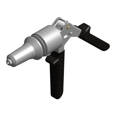
Gesipa FireRex C-WT Guide

FireRex® C-WT
Pneumatic-hydraulic blind rivet nut setting gun
Operating manual with spare parts list
SFS Group Germany GmbH
Division Riveting – GESIPA®
Nordendstraße 13-39
64546 Mörfelden-Walldorf
Germany
T +49 (0) 6105 962 0
F +49 (0) 6105 962 287
www.gesipa.com

2
GB
1638027 Operating manual FireRex®C-WT

3
GB
1638027 Operating manual FireRex®C-WT
Overview
4
32
1
C B A
E
D
I, J
H
G
B
A
C
F
3
2
1
1
7
8
2
12;13
9
X
3
2
1
4
10
3
2
1
1
7
8
2
12;13
9
X
3
2
1
4
10
3
2
1
1
7
8
2
12;13
9
X
3
2
1
4
10
3
2
1
1
7
8
2
12;13
9
X
3
2
1
4
10
3
2
1
1
7
8
2
12;13
9
X
3
2
1
4
10
3
2
1
1
7
8
2
12;13
9
X
3
2
1
4
10
x

4
GB
1638027 Operating manual FireRex®C-WT
Table of Contents
1. Overview (See images 1 - 4).............................................................................5
2. Blind rivet nut setting tool FireRex®C-WT.........................................................5
2.1 Correct use.................................................................................................5
2.2 Safety instructions......................................................................................5
2.3 Work capacity.............................................................................................6
2.4 Technical data ............................................................................................6
2.5 Equipment/accessories..............................................................................7
3. Conguration.....................................................................................................7
3.1 Pneumatic circuit diagram..........................................................................9
3.2 Process data evaluation...........................................................................11
4. Starting procedure...........................................................................................11
4.1 Oiler..........................................................................................................12
4.2 How to change a threaded mandrel.........................................................12
4.3 How to set threaded mandrel length "X" ..................................................12
5. How to adjust the setting force........................................................................12
6. Sequence of operations ..................................................................................14
6.1 How to wind down a nut...........................................................................14
6.2 How to set the blind rivet nut....................................................................14
6.3 How to remove a nut manually by turning................................................14
7. Maintenance and care.....................................................................................14
8. Troubleshooting...............................................................................................15
9. Notes on environment .....................................................................................16
10. Warranty..........................................................................................................16
11. Declaration of Conformity EC..........................................................................17

5
GB
1638027 Operating manual FireRex®C-WT
1. Overview (See images 1 - 4)
2. Blind rivet nut setting tool FireRex®C-WT
The blind rivet nut tool is designed exclusively for setting blind rivet nuts and blind rivet nut
studs as described in the operating instructions. Please comply with all safety instructions!
2.1 Correct use
Item Designation Image
A Locknut 1, 4
B Nosepiece 1, 4
C Threaded mandrel 1, 4
D Slide Wind down button 1
E Bead breaking process (solenoid
valve)
1
FSlide 4
G Adjustable screw with colour scale 3
H Display window 3
IOilrellscrew 2
J Seal 2
• The blind rivet nut setting tool should only be used for setting blind rivet nuts and blind rivet
nut studs.
• Improperusewhenwindingdownandsettingnutsposesariskofcrushingyourngers!
• Do not overload the blind rivet nut setting tool; work within the prescribed work capacity.
• Do not exceed the permitted operating pressure.
• Donotrivetoutsideofrivetingholes!
• Checkconnectinglinesforcompressedairatregularintervalsforforcetandtightness.
• Disconnect the device from the compressed air network prior to carrying out any
maintenance work to the blind rivet nut setting tool, changing threaded mandrels or when
not in use.
• When working with the tool, always wear protective goggles. Personal protection like clothes,
gloves, safety helmet, ear protection and anti-fall protection are highly recommended.
• When depositing the blind rivet setting tool, make sure that it cannot fall.
2.2 Safety instructions

6
GB
1638027 Operating manual FireRex®C-WT
2.4 Technical data
2.3 Work capacity
The blind rivet nut setting tool is suitable for setting M5 to M10 blind rivet nuts and blind rivet
studs made of all materials and M12 made of aluminium and steel.
• Repair work must be carried out by skilled personnel. Use genuine parts for repair at all
times. In case of doubt, always send the complete blind rivet nut setting tool back to the
supplier or to GESIPA®.
• Avoidexcessivecontactwithhydraulicoil.Ifirritationoftheskinoccurs,washaectedskin
partsthoroughlywithwater!
• Dispose of hydraulic waste oil according to current regulations.
Weight 5.2 kg
Working pressure 5 to 7 bar
Gun stroke max. 10 mm
Hose connection Ø8 mm (1/4)"
Compressed air consumption c. 2 - 4 litre/setting process (dependent on nut size)
Setting force at 6 bar 22 kN
Hydraulic oil ca. 30 ml (ISO VG 32 bis 46)
Noise emission Lpa 75 dB, Measurement uncertainty K = 3dB
Vibration < 2,5 m/s², Measurement uncertainty K = 1,5 m/s²
Compressed air quality Filtered and controlled via a pressure regulator (oiled or non-oiled;
oiled air prolongs the service life of the pneumatic motor)
Setting tool

7
GB
1638027 Operating manual FireRex®C-WT
Supply voltage 24 Volt DC (no galvanic isolation in the device)
Permissible supply voltage range 10-28 Volt
Power consumption 1.5 Watt
Behaviour in the event of a failure of the supply
voltage
Automatic data retention after power failure
Laufzeit Stützbatterie (CR2032) für Realtime-
clock, typ.
5 years
Interface RS232
Interface transmission rate 9600Baud / 115200Baud
Interface protocol 8 data bits, 1 stop bit, parity none
Hardware handshake CTS/RTS
Process data memory max. 260,000 process data sets
Proledatamemory 512prolesin20prolelists
Temperature range 0-50°C
Protection class IP 20
Evaluation window up to max. 3
Process data module
2.5 Equipment/accessories
Threaded mandrels and nose-
piece
Dependent on selected device version in working position
Tool Hexagon screw driver SW 3
2 x double open-end spanner SW24/27
Suspension Loop Extendable from device top
Scope of delivery 1oilllingcontainer(1625612)
1 bottle of hydraulic oil 100ml (1445294)
USB stick (GrivCheck 2.0 software, GrivCheck 2.0 software user
manual, operating manual with spare parts list)
3. Conguration
In addition to the standard tool, the FireRex®C-WT blind rivet nut setting tool is equipped
with sensors for recording the setting force and setting stroke during the setting process. A
process data module is integrated into the head housing of the blind rivet nut setting tool that
evaluates the recorded process data. The process evaluation is visualised on the blind rivet
nut setting tool by means of an LED integrated into the housing. The sensors employed in the
blind rivet nut setting tool and the process data module are maintenance-free. Figure 1 shows
thecongurationoftheFireRex®C-WT with setting process monitoring.

8
GB
1638027 Operating manual FireRex®C-WT
cable assembly
bead breaking
process
Air motor
Device holder
connection block
pressure relay
valve
Data cable
Air supply
Threaded mandrel
Nosepiece
Force/stroke
sensors
Figure 1

9
GB
1638027 Operating manual FireRex®C-WT
Air motor
3.1 Pneumatic circuit diagram
Pneumatic attachments (1544052)
Item Description Part No.
1.1, 1.2 Solenoid valve 1630132
1.3 Solenoid valve 1600130 / 1630131
1.4 Solenoid valve 1630130 / 1630131
1.5 Connecting lead (for solenoid
valve)
1630134
1.6 Plug connection 1445957
1.7 Blind plug 146142
Pneumatic hose 1445398
Pneumatic feed unit (1518269)
Item Description Part No.
2.1, 2.2 Pressure control valve 1630139
2.3 Mounting bracket 1630146
2.4 Plug connection 1445932
2.5, 2.6 One-way restrictor 1572561
2.7 Guide cylinder 1630147
2.8 Proximity switch 1562253
2.9 Connecting cable (for proximity
switch)
1630144
2.10 Adapter bracket 1630146
Screw 1445977
Plate 1445361

10
GB
1638027 Operating manual FireRex®C-WT

11
GB
1638027 Operating manual FireRex®C-WT
4. Starting procedure
Prior to operating the blind rivet nut setting tool, attach the relevant threaded mandrel with
nosepiece to match the thread size.
Before starting the blind rivet nut setting tool, read and observe the operating instructions and
safety information and keep in a safe place. Have the compressed air mains connection to the
blindrivetnutsettingtoolmadeaqualiedperson.Initialcommissioningmustalsobecarried
out together with a service technician from GESIPA®. For editing of the blind rivet nut setting
tool, it must be connected to a PC with Windows 7 or higher using the GESIPA®GrivCheck
2.0 software and a USB adapter cable (Article No. 1435512).
3.2 Process data evaluation
The setting process is monitored on the FireRex®by evaluating the setting force and setting
stroke during the setting process in the material to be joined. The evaluation criteria are the
maximum setting force Fm and the setting stroke Sm up to standstill. A blind rivet nut joint is
evaluatedasOKwhenthisvaluepairiswithinadenedevaluationwindow.Ifthevaluepair
liesoutsidethiswindow,orleavesthewindowtothepreviouslydenedside,theprocessis
evaluated as NOK.

12
GB
1638027 Operating manual FireRex®C-WT
4.2 How to change a threaded mandrel
• Disconnect the blind rivet nut setting tool from the compressed air network.
• Detach locknut A, using double open-end spanner SW.
• Unscrew nosepiece B with locknut A
• PushslideKbackallthewaytobuerandholdtight
• Unscrew threaded mandrel C
• Insert new threaded mandrel C of same size (if worn out) or threaded mandrel C of match-
ingthreadsizeallthewaytobuer.
• Release slide. At the same time make sure that the threaded mandrel C is locked safely
inside the hexagon socket of the slide. If required, unscrew threaded mandrel C slightly
until the slide F locks.
• Insert a matching nosepiece B for each thread size using locknut A and lock loosely with
locknut, using a double open-ended spanner.
• Set threaded mandrel length "X", as described under item 4.3.
4.3 How to set threaded mandrel length "X"
• Detach locknut A, using double open-end spanner.
• Adjust threaded mandrel length "X", according to nut length (see image 3) by turning
nosepiece B.
• Make full use of depth of thread for closed blind rivet nuts (image 3).
• Secure nosepiece B using locknut A.
The FireRex®C-WT is adjusted to a setting force suitable for the respective blind rivet nut size
(e.g. M6). This ensures that all blind rivet nuts of certain thread dimensions (e.g. M6x15.5 or M6x18)
butwithdieringnutlengthsarealwayssetpreciselyasintendedintomaterialsofvaryingthicknesses.
5. How to adjust the setting force
4.1 Oiler
• To prolong the service life of the pneumatic motor, it should be lubricated by operating the FireRex®
C-WT blind rivet nut setting tool with oiled air.
• Thelubricatormayonlybeintegratedinline6(twisto).
• The original GESIPA®oil can be used for lubrication.
• The oiler should be set such that approx. 1 drop of oil is added to the compressed air every 300-
350settingoperations.Onellingofthesuppliedoileristhereforesucientfor600,000-700,000
setting operations.
• Analoilvolumehastobedeterminedoveraprolongedperiodofoperation.Payattentioninparti-
cular here whether, e.g. oil droplets stick to the device. In this case the oil volume has to be reduced.

13
GB
1638027 Operating manual FireRex®C-WT
Turning in setscrew G increases the setting force of the rivet tool; unscrewing decreases
the setting force!
To adjust the setting force, follow the sequence of operations below:
1. The setting force can be pre-set using the enclosed colour code chart. The right colour code
can be selected on the colour code chart according to the nut sizes and the nut materials
(e.g. M6 – steel Colour code red)
2. Using the enclosed hexagon screw driver SW 4, turn the set screw with colour scale Ito the
selected colour code in the display window.
3. Winding down the blind rivet nut to be set (see item 6.1). Insert the blind rivet nut into the mate-
rial to be riveted. For materials of varying thicknesses it is advisable to select maximum
material thickness.
4. Triggering of a setting operation by driving the solenoid valves (1.1 and 1.2). Then check the
nut you have set:
• The process can be monitored visually or in the GrivCheck 2.0 software.
• Ifthenutisnotsucientlydeformedduringthisprocess,usethehexagonscrewdriver
SW 3 to screw in the set screw with colour scale Gby c. 0.5 rotations. Then repeat the
setting sequence with a new nut and check once again.
• Ifthenutbecomestoodeformed(e.g.diculttoremove;nutthreaddeformed),the
set screw Gshould be unscrewed about 1 rotation. Then repeat the setting sequence with
a new nut and check once again.
Alu
Alu
Stahl
Steel
Edelstahl
Stainless steel
M5
M6
M8
M10
M12

14
GB
1638027 Operating manual FireRex®C-WT
6.2 How to set the blind rivet nut
• Insert the wound down blind rivet nut all the way into the drilled hole of the work piece.
• Start the setting process by venting the solenoid valves (1.1 and 1.2)
• Whenthesetsettingforceisreached(seepoint5!),thethreadedmandrelmovesforward
again. The bead breaking process is started by driving solenoid valve (1.3).
• The solenoid valves should be controlled via a PLC supplied by the customer.
• If, for example, the solenoid valve is switched too early during a setting operation and the
threaded mandrel is therefore not retracted completely, or the nut was positioned crooked
during riveting, a bead breaking process can be started manually by driving solenoid valve
(1.3) again.
• If the threaded mandrel cannot be retracted by driving solenoid valve (1.3) (e.g. thread in
the nut deformed too much), the threaded mandrel can be retracted by hand. To do this,
insert the SW 3 Allen key into the socket D on the air outlet of the pneumatic motor (see
Figure 1) and turn in anti-clockwise direction to carefully release the threaded mandrel.
6.3 How to remove a nut manually by turning
The blind rivet nut setting tool must be kept in a dry place. Worn threaded mandrels must
be replaced as described under item 3.1, as required. After prolonged use it may become
necessary to top up or replace the hydraulic oil. The hydraulic oil should only be replaced by
qualiedpersonnel.
7. Maintenance and care
6. Sequence of operations
• Position blind rivet nut without tilting on threaded mandrel C.
• Then use the blind rivet nut setting tool to press the threaded mandrel C towards the rivet
tool. This action will automatically start the winding down process.
• Donotpressactivationbutton!
• Keep a tight hold of the blind rivet nut throughout the winding down process until the blind
rivetnutrestsonnosepieceB.Thewindingdownprocessnishesautomatically.
6.1 How to wind down a nut

15
GB
1638027 Operating manual FireRex®C-WT
8. Troubleshooting
Not possible to wind down nut
Cause Remedy
Nut thread defective Use new nut
Threaded mandrel defective Replace threaded mandrel (see item 3.1)
To top up the hydraulic oil follow the sequence of operations below:
• Connect the blind rivet nut setting tool to the compressed air network (it moves to starting
position)
• Disconnect the blind rivet nut setting tool from the compressed air network.
• Unscrew nosepiece B using locknut A.
• UnscrewoilrellscrewIandsealJusingTorxscrewdriverT20.
• Screwontheoiltop-uptankwithcoversuppliedandlltoapprox.50%withhydraulicoil
• At threaded mandrel C, move the piston unit carefully back and forth up to the stops by
hand until the hydraulic oil comes out bubble-free; push the piston unit completely back
andleaveattherear(hydraulicoillevelinoiltop-uptankdrops!).Caution!Ensurethatno
airisdrawnin!
• Unscrew the oil top-up tank from the blind rivet nut setting tool.
• ScrewinoilllerplugIwithgasketJusingaTORX®screwdriver T20.
• Connect the blind rivet nut setting tool to the compressed air network via a pressure
regulatorandthensetthepressureregulatorto0bar.Caution!Donottriptheactivation
button.
• UnscrewoilllerplugIandgasketJusingaTORX®screwdriver T20.
• Screw on the oil top-up tank with cover supplied.
• Gradually increase the air pressure to mains pressure at the regulator; any excess hydraulic
oilispressedout!
• Unscrew the oil top-up tank from the blind rivet nut setting tool and wipe up the escaped
hydraulic oil.
• ScrewinoilllerplugIwithgasketJusingaTORX®screwdriver T20.
• Screw on mouthpiece B with lock nut A.
Regular maintenance will extend the service life of your high-quality GESIPA®
tools and they should be serviced at least every 2 years by an authorised
workshop or by GESIPA®Service. For tools that are used intensively, we
recommend servicing ahead of schedule.

16
GB
1638027 Operating manual FireRex®C-WT
Nut is not removed by turning
Cause Remedy
Nut thread deformed Setting force too strong reduce (see item 4)
Removal period too short Activate solenoid valve (1.3) for longer
Setting force not reached Activate solenoid valve (1.1 and 1.2) for longer
untilthenutisautomaticallytwistedo;topup
the hydraulic oil, if necessary; increases the
mains air pressure (max. 7)
Nut stuck on threaded mandrel Reducesettingforce(seepoint5).Backo
solenoid valve (1.3) or unscrew using an Allen
key (see point 6.3)
Set nut is loose
Cause Remedy
Setting force too low Increase setting force (see item 4)
Air pressure too low Increase air pressure to 5-7 bar
9. Notes on environment
Dispose of hydraulic waste oil according to current environmental regulations.
Observeregulationsaboutdangeroussubstances!
10. Warranty
The applicable terms and conditions of guarantee shall apply and can be viewed under following
link: www.gesipa.com/agb

17
GB
1638027 Operating manual FireRex®C-WT
11. Declaration of Conformity EC
We hereby declare that the design and construction of the tool named below, as well as the
version that we have put on the market, complies with applicable fundamental health and safety
requirements stipulated in EU directives. Tool modications made without our authorisation
shall render this declaration void. The safety information in the product documentation provided
must be observed. This document must be retained.
FireRex®C-WT
Authorised documentation representative:
SFS Group Germany GmbH
Division Riveting – GESIPA®
Nordendstraße 13-39
D-64546 Mörfelden-Walldorf
ppa. Dipl.-Ing. Stefan Petsch
Head of Operations Tools
Member of Division Management
EC UKCA
2006/42/EG The Supply of Machinery (Safety) Regulation 2008
DIN EN ISO 12100:2011-03 The Electromagnetic Compatibility Regulations 2016
DIN EN ISO 11148-1:2012-06 The Waste Electrical and Electronic Equipment Regulations 2013
DIN EN 82079-1:2013-06 The Restriction of the Use of Certain Hazardous Substances in Electrical
and Electronic Equipment Regulations 2012
EN ISO 11148-1:2011
EN 55014-1:2016
EN 55014-2:2015

1638027 - 03/2023
Your partner
Table of contents
Other Gesipa Rivet Tools manuals

Gesipa
Gesipa FireFox 2 User manual

Gesipa
Gesipa TAURUS 4 CF Guide

Gesipa
Gesipa FireFox F User manual

Gesipa
Gesipa PH 1 Guide

Gesipa
Gesipa PowerBird Guide

Gesipa
Gesipa taurus 1 User manual

Gesipa
Gesipa AccuBird Guide

Gesipa
Gesipa AccuBird Pro Guide

Gesipa
Gesipa PH 2000 Guide

Gesipa
Gesipa TAURUS 3 C User manual

Gesipa
Gesipa FireBird Pro User manual

Gesipa
Gesipa taurus 3 Setup guide

Gesipa
Gesipa PowerBird Pro Gold Edition Guide

Gesipa
Gesipa FireBird Gold Edition User manual

Gesipa
Gesipa FireBird Pro Guide

Gesipa
Gesipa taurus 1 Guide

Gesipa
Gesipa AccuBird Pro User manual
Gesipa
Gesipa PowerBird Pro Gold Edition Guide

Gesipa
Gesipa taurus 1 Guide

Gesipa
Gesipa FireBird Pro User manual