manuals.online logo
Brands
  1. Home
  2. •
  3. Brands
  4. •
  5. Häfele
  6. •
  7. Indoor Furnishing
  8. •
  9. Häfele Height adjustable pull out larder unit User manual

Häfele Height adjustable pull out larder unit User manual

2 x Door connecting strips (E)
2 x M6 x 50 mm
Connecting bolt (I) 2 x M6 x 10 mm
Round head bolt (L)
1 x Guide roller (D)
12 x M5 x 6.0 mm
Round head bolt (M)
3 x Brackets (B) 3 x Plate (C)
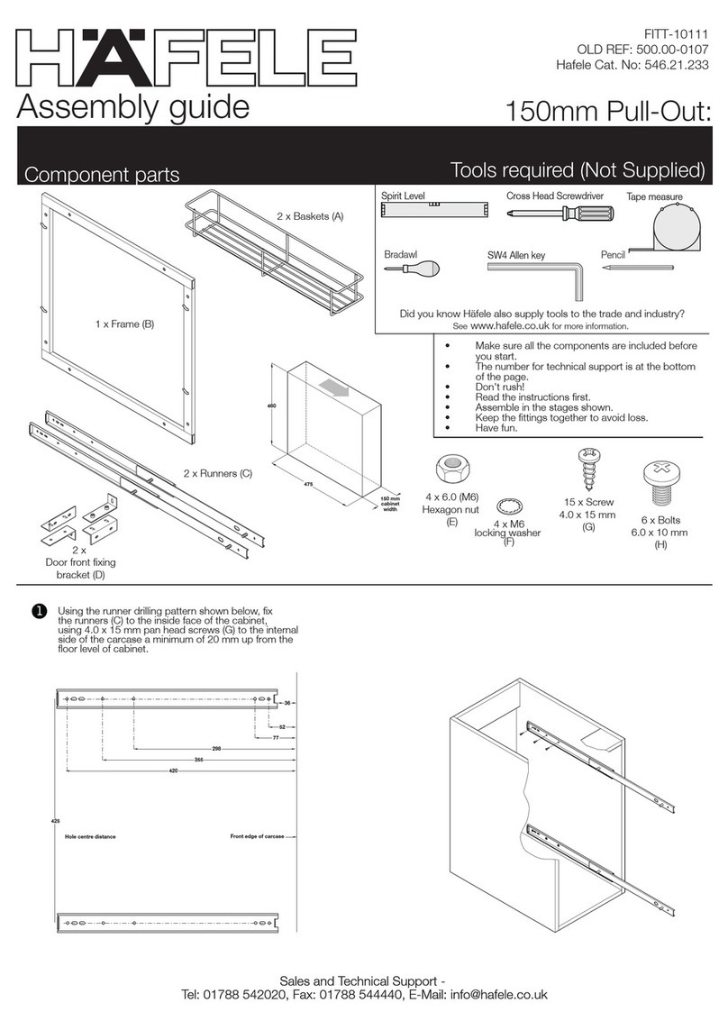
Tools required (Not Supplied)
Component parts
Height adjustable pull out larder unit:
Assembly guide
Sales and Technical Support -
Tel: 01788 542020, Fax: 01788 544440, E-Mail: [email protected]
Sales and Technical Support -
Tel: 01788 542020, Fax: 01788 544440, E-Mail: [email protected]
• Make sure all the components are included before
you start.
• The number for technical support is at the bottom
of the page.
• Don't rush!
• Read the instructions first.
• Assemble in the stages shown.
• Keep the fittings together to avoid loss.
• Have fun.
1 x Frame (A)
1 x Runner (F)
500.00-0102
Installed height 950 - 1200 mm = 3 baskets
Installed height 1200 - 1450 mm = 4 baskets
Installed height 1450 - 1700 mm = 4 baskets
Installed height 1700 - 1950 mm = 5 baskets
Installed height 1950 - 2200 mm = 5 baskets
2 x M8 x 40 mm
Round head bolt (J)
36 x M4 x 15 mm
Pan head screw (N)
48 mm pins
x 2 per basket (Q)
2 x M6 x 25 mm
Round head bolt (K)
pin caps
x 2 per pin (R)
8 x M5 x 10.0 mm
Flat head screw (O)
Check off components as shown in diagram and lay on flat surface
1
Basket (H)
Pencil
Bradawl
Spirit Level Cross Head Screwdriver Tape measure
Did you know Häfele also supply tools to the trade and industry?
See www.hafele.co.uk for more information.
SW4 Allen key
FITT-10057
Issue - 01
3
Threaded hole bracket
Flat head screw
Working outside the carcase, secure the two part frame together by
inserting one of the four connector strips into the bottom section of
the frame and align the holes. BE CAREFUL NOT TO LET THE CONNECTORS
SLIP DOWN INSIDE THE MAIN FRAME! Insert the one of the eight M5 x 10mm
screws. Repeat this procedure for the other three frame connectors as shown
in the drawing making sure the cut outs in the frame are on the same side top and
bottom, Slide the top section of the frame over the secured connectors
aligning the holes and secure using the remaining four M5 x 10mm screws.
Make sure the screws are securely tightened before proceeding.
4 x Frame
connectors (G)
4Draw a centre line on the top and bottom panel of the carcase.
Mark positions of fixing holes required for the bottom runner.
Centre line
Centre line
M8 x 40 mm
round head bolt (J)
M6 x 50 mm
connecting bolts (I)
3Attach the top and bottom door panel hanging brackets
(B) to frame (A) using 2 x M6 x 10.0 mm round head bolt
(L).
M6 x 10.0 mm
M6 x 10.0 mm
Height adjustable pull out larder unit:
A
ssembly guide
Sales and Technical Support -
Tel: 01788 542020, Fax: 01788 544440, E-Mail: [email protected]
Sales and Technical Support -
Tel: 01788 542020, Fax: 01788 544440, E-Mail: [email protected]
Steps 2 to 6
2Then position left-hand and right-hand runner (F) together and then
secure the frame (A) to the runner (F) using 2 x M6 x 50.0 mm (I) bolt.
Make sure the front of the frame and front of runner line up. Insert
2 x M8 x 40.0 mm bolts (J) as shown, but do not tighten at this stage.
5
Align runner (F) with the centre line on bottom panel and 6 mm from
front edge of the carcase. Use 10 x M4 x 15.0 mm pan head screws
(N) to secure the runner. Using five holes on each side of the runner,
use the 1st, 3rd, 4th, 6th, and 8th holes.
6Position the roller (D) at the front of the cabinet and
align with the centre line on the top panel and secure
using 2 x M4 x 15.0 mm pan head screws (N).
Centre line
Centre line
Height adjust frame
to fit into roller
and clamp using
2 x M6 x 25 mm
round head bolt (K)
Plan veiw
Front edge of carcase
64
89
127
43 127 64
Height adjustable pull out larder unit:
A
ssembly guide
Sales and Technical Support -
Tel: 01788 542020, Fax: 01788 544440, E-Mail: [email protected]
Sales and Technical Support -
Tel: 01788 542020, Fax: 01788 544440, E-Mail: [email protected]
Steps 7 to 10
If a false double door effect is to be used, then connect the
two door panels using the 2 door panel connectors (E) and
8 x M4 x 15.0 mm pan head screws (N).
7
Attach the top and bottom door panel hanging plates (C) to the
door panel using 4 x M4 x 15.0 mm pan head screws (N) per bracket.
Use the measuring guide above to assist. Then attach the third door
panel hanging plate close to the door handle positioned, again using
4 x M4 x 15.0 mm pan head screws (N).
8
Insert loosely 2 x M5 x 6.0 mm raised head screws (M) into each of
the door panel hanging plates (C), then locate these screws into
the door panel hanging brackets (B) attached to the main frame (A).
Then secure the 2 x M5 x 6.0 mm round head screws (M) on each
of the door panel hanging plates (C).
9
A = 286 mm + door overlay
Installed unit height 950 - 1200 mm. B = 400 mm
Installed unit height 1200 - 1450 mm, B = 624 mm
Installed unit height 1450 - 1700 mm, B = 1024 mm
Installed unit height 1700 - 1950 mm, B = 1175 mm
Installed unit height 1950 - 2200 mm, B = 1400 mm
C = 127.5 mm for a 300 mm carcase
177.5 mm for a 400 mm carcase
227.5 mm for a 500 mm carcase
277.5 mm for a 600 mm carcase
D = 239 mm for a 300 mm carcase
339 mm for a 400 mm carcase
439 mm for a 500 mm carcase
539 mm for a 600 mm carcase
A
B
Attach the third door panel hanging bracket (B) around the
frame onto the door panel hanging plate closely situated
behind the door handle position to stop the centre of the
door flexing, using 2 x M5 x 6.0 mm round head bolts (M).
10
C
D
11
Adjustment of the door can be achieved by partially unscrewing,
Screws 1 for horizontal adjustment,
screw 2 for vertical adjustment,
until the desired position is achieved. Screws 3 can then be
losened / tightened for in and out adjustment.
Height adjustable pull out larder unit:
A
ssembly guide
Sales and Technical Support -
Tel: 01788 542020, Fax: 01788 544440, E-Mail: [email protected]
Sales and Technical Support -
Tel: 01788 542020, Fax: 01788 544440, E-Mail: [email protected]
Steps 11 to 14.
12
For vertical/tilt alignment of the door, loosen fixing bolts (I)
and raise front or back of frame as necessary, using
adjusting bolts (J). Then re-tighten fixing bolts (I).
II
JJ
13
Place the baskets (H) in the desired position on the frame
using 2 x metal pins (Q) to hang the baskets (H). Then
place 2 x end caps (R) on each end of the metal pins (Q)
to lock them in place.
1
12
33
3
14 Finished unit with larder pull-out

Other Häfele Indoor Furnishing manuals

Häfele 580.57.040 User manual

Häfele

Häfele 580.57.040 User manual

Häfele 400.50.486 Operating manual

Häfele

Häfele 400.50.486 Operating manual

Häfele TE601 Work Classic C-800 User manual

Häfele

Häfele TE601 Work Classic C-800 User manual

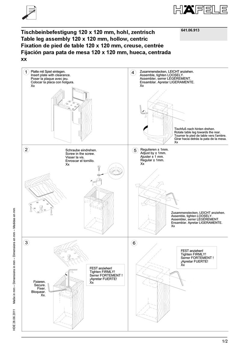
Häfele 641.06.913 User manual

Häfele

Häfele 641.06.913 User manual

Häfele AdjustableTableSystem 630.44 Series User manual

Häfele

Häfele AdjustableTableSystem 630.44 Series User manual

Häfele 271.92.200 User manual

Häfele

Häfele 271.92.200 User manual

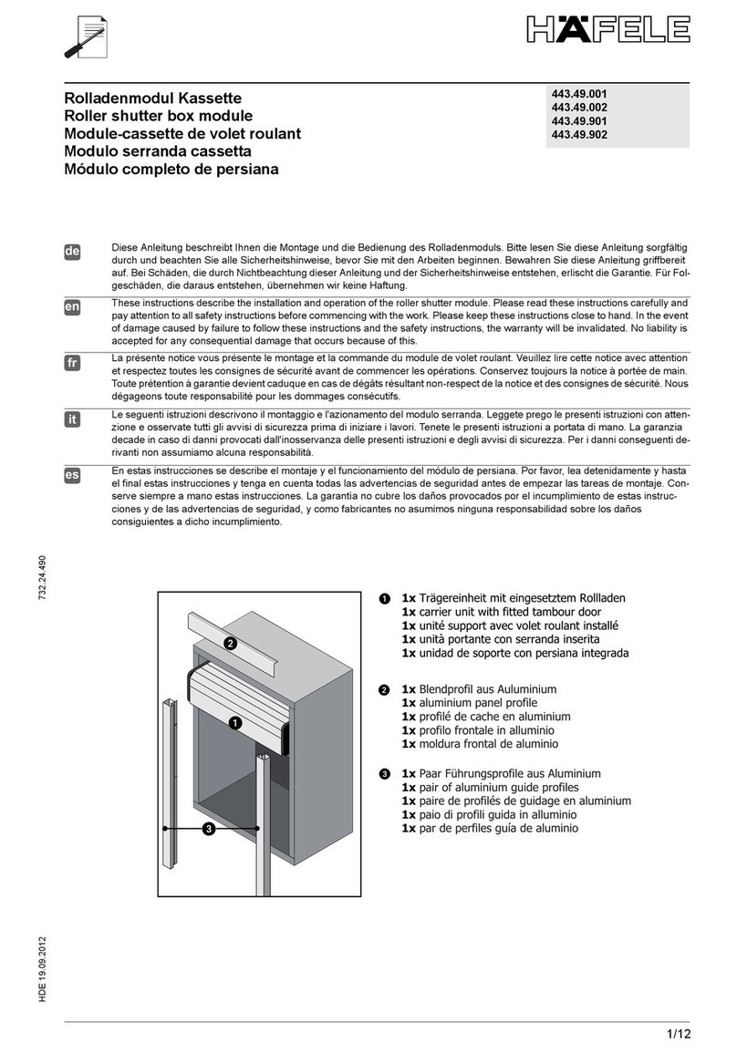
Häfele 443.49.001 User manual

Häfele

Häfele 443.49.001 User manual

Häfele Tavoletto 271.97.300 User manual

Häfele

Häfele Tavoletto 271.97.300 User manual

Häfele Nova Pro Scala User manual

Häfele

Häfele Nova Pro Scala User manual

Häfele Verso 372.68 Series User manual

Häfele

Häfele Verso 372.68 Series User manual

Häfele Aquasys 983.19.010 User manual

Häfele

Häfele Aquasys 983.19.010 User manual

Häfele Tavoletto 271.97.300 User manual

Häfele

Häfele Tavoletto 271.97.300 User manual

Häfele Suzie Q Corner carrousel fitting Guide

Häfele

Häfele Suzie Q Corner carrousel fitting Guide

Häfele 271.92.260 User manual

Häfele

Häfele 271.92.260 User manual

Häfele FITT-10111 User manual

Häfele

Häfele FITT-10111 User manual

Häfele Dialock FT 120 User manual

Häfele

Häfele Dialock FT 120 User manual

Häfele 546.21.230 User manual

Häfele

Häfele 546.21.230 User manual

Häfele KYOTO TOWEL RING User manual

Häfele

Häfele KYOTO TOWEL RING User manual

Häfele PARTY 600 411/78.1500.22 User manual

Häfele

Häfele PARTY 600 411/78.1500.22 User manual

Häfele CLEVER User manual

Häfele

Häfele CLEVER User manual

Häfele W300-IMP User manual

Häfele

Häfele W300-IMP User manual

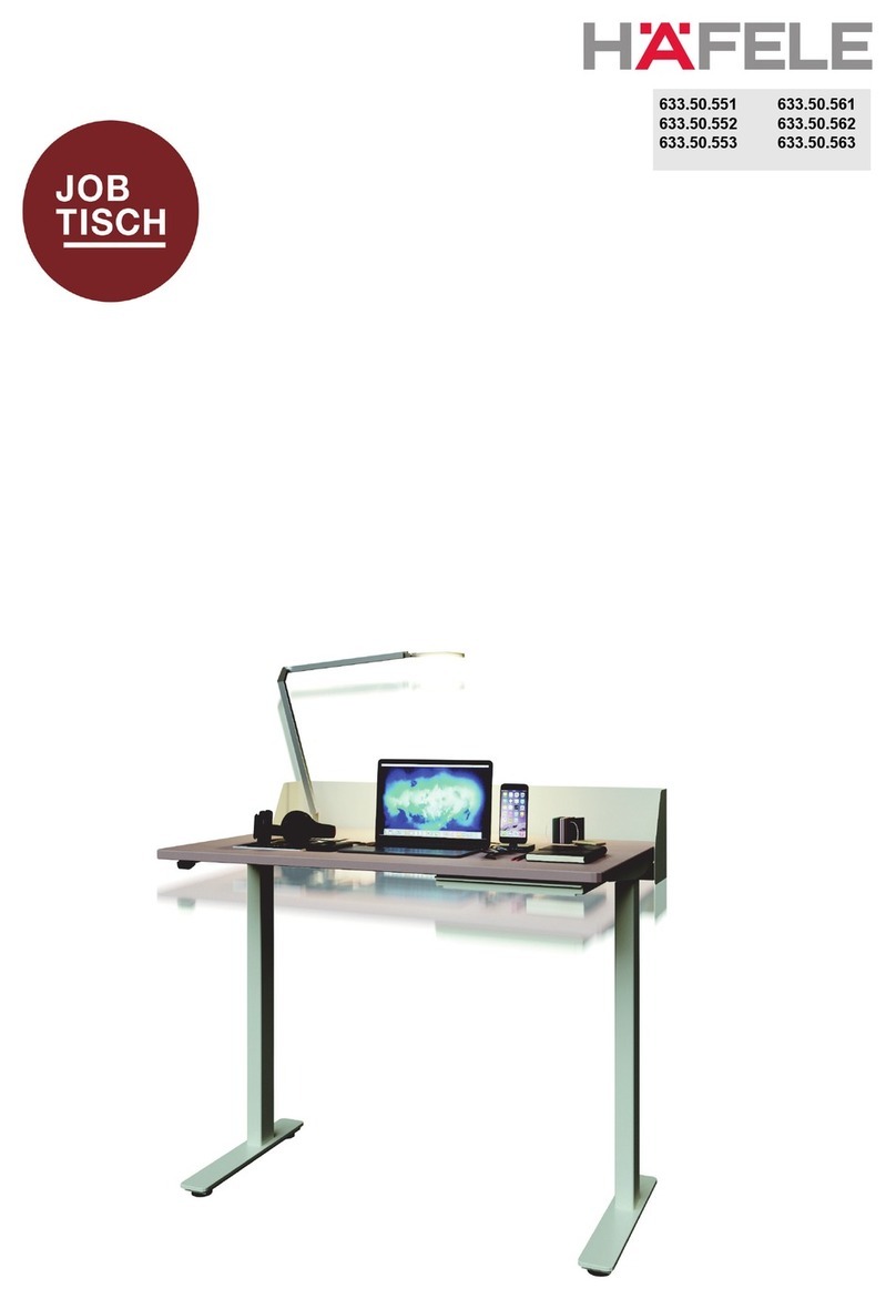
Häfele JobTisch 633.50.551 User manual
Häfele

Häfele JobTisch 633.50.551 User manual

Häfele 732.22.284 User manual

Häfele

Häfele 732.22.284 User manual

Häfele Tavoletto 271.97.301 User manual
Häfele

Häfele Tavoletto 271.97.301 User manual

Popular Indoor Furnishing manuals by other brands

Noble House Home Furnishings END TABLE Assembly instructions

Noble House Home Furnishings

Noble House Home Furnishings END TABLE Assembly instructions

SouthShore 038 Assembly instructions

SouthShore

SouthShore 038 Assembly instructions

ricoo FS0116 Assembly instructions

ricoo

ricoo FS0116 Assembly instructions

Songmics VASAGLE LLS46 manual

Songmics

Songmics VASAGLE LLS46 manual

Alice's Garden ACAPULCO PEX1 manual

Alice's Garden

Alice's Garden ACAPULCO PEX1 manual

Safavieh Furniture Lylia MED9622 manual

Safavieh Furniture

Safavieh Furniture Lylia MED9622 manual

Home Decorators 4030E-HLRC Assembly instructions

Home Decorators

Home Decorators 4030E-HLRC Assembly instructions

OVE CARRAN 60 installation manual

OVE

OVE CARRAN 60 installation manual

Hailey Home CT0071 Assembly instructions

Hailey Home

Hailey Home CT0071 Assembly instructions

Amart Furniture ROSCO 64397 Assembly instruction

Amart Furniture

Amart Furniture ROSCO 64397 Assembly instruction

Uberhaus RFVA-0014 Operator's manual

Uberhaus

Uberhaus RFVA-0014 Operator's manual

Argos Home Venetia manual

Argos

Argos Home Venetia manual

Brentwood HOME Base II owner's manual

Brentwood

Brentwood HOME Base II owner's manual

ED 1580WC-24-201 Assembly instructions

ED

ED 1580WC-24-201 Assembly instructions

BED BATH & Beyond C3012T43-HKW/AGY-5X Assembly instruction

BED BATH & Beyond

BED BATH & Beyond C3012T43-HKW/AGY-5X Assembly instruction

Signature Design by Ashley 3500212 manual

Signature Design by Ashley

Signature Design by Ashley 3500212 manual

Ameriwood HOME 5685341COM Instruction booklet

Ameriwood HOME

Ameriwood HOME 5685341COM Instruction booklet

Thonet 7000 f/p design Assembly instructions

Thonet

Thonet 7000 f/p design Assembly instructions

manuals.online logo
manuals.online logoBrands
  • About & Mission
  • Contact us
  • Privacy Policy
  • Terms and Conditions

Copyright 2025 Manuals.Online. All Rights Reserved.