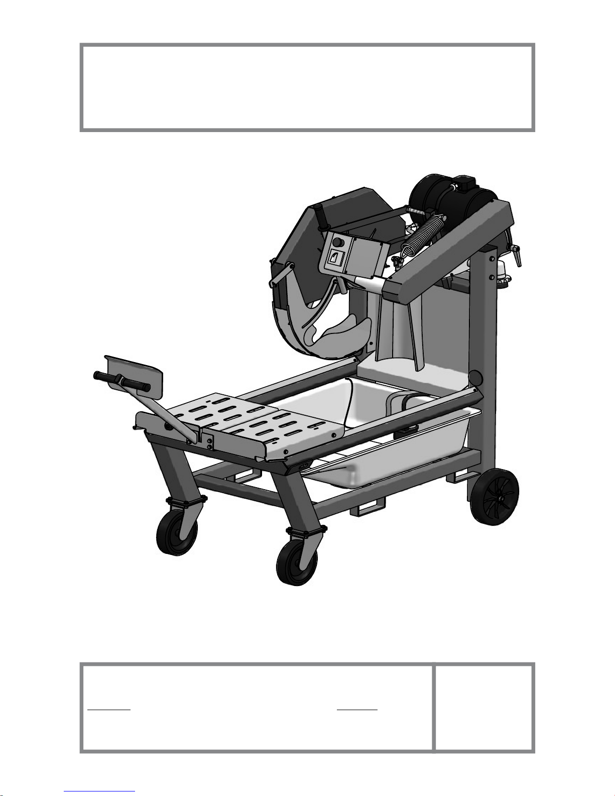
IMER MASONRY 700 Guide

MASONRY 700
SAWING MACHINE
OPERATING, MAINTENANCE, SPARE PARTS MANUAL
IMER WEST
3654, Enterprise Avenue
Hayward, CA 94545
Ph. 510.670.7970
Fax 510.783.4255
IMER EAST
221 Westhampton Place
Capitol Heights, MD 20743
Ph. 301.336.3700
Fax 301.336.6687
IMER
U.S.A. Inc.
Toll Free: 800.275.5463
www.imerusa.com
2010/07 - R04
Cod. 3228131

IMER U.S.A. Inc.
MASONRY 700
2
FIG. 1
REF.
DESCRIPTION
1
Frame
2
Screw
3
Guide bar
4
Carriage
5
Trolley clamping
6
Workpiece
7
Spray guard
8
Motor
9
Junction box
10
Plug
11
Cutting head group
12
Blade
13
Disc cover
14
Blade cover
15
Drum
16
Water pump
17
Adjusting cut lever
18
Cam
Special attention must be given to warnings with this symbol:

IMER U.S.A. Inc.
MASONRY 700
3
Dear Customer,
Congratulations on your choice of purchase: this IMER saw, the result of
years of experience, is a fully reliable machine and is equipped with the
latest technical innovations.
- WORKING IN SAFETY
To work in complete safety, read the following instructions care-
fully.
This OPERATION AND MAINTENANCE manual must be kept on site
by the person in charge, e.g. the SITE FOREMAN, and must always be
available for consultation.
This manual is to be considered an integral part of the machine, and
it must be preserved for future reference (EN 12100/2) throughout the
cement may be requested from the saw manufacturer.
The manual contains important information regarding site preparation,
installation, machine use, maintenance procedures and requests for
spare parts. Nevertheless, the installer and the operator must both have
adequate experience and knowledge of the machine prior to use.
To guarantee complete safety of the operator, safe operation and long
life of equipment, follow the instructions in this manual carefully, and
observe all safety standards currently in force for the prevention of
accidents at work. Use personal protection (safety footwear, suitable
clothing, gloves, goggles, etc.).
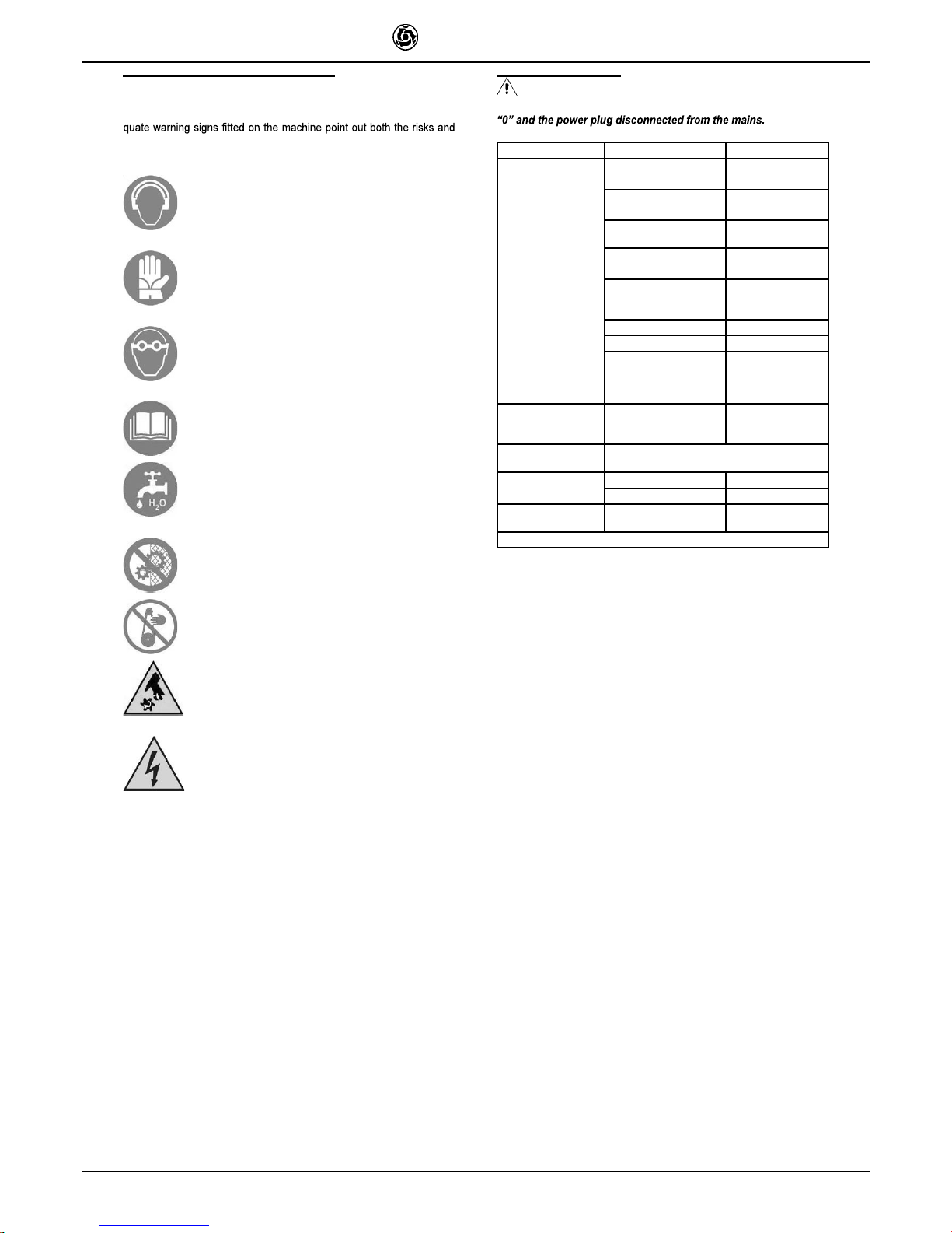
- The use of protective goggles is compulsory.
- Ear protection must be worn at all times.
- Make sure that warning signs are always legible.
the steel structure or working parts of the machine.
IMER INTERNATIONAL declines all responsibility for non-compliance
with laws and standards governing the use of this equipment, in par-
ticular; improper use, defective power supply, lack of maintenance,
instructions contained in this manual.
IMER INTERNATIONAL is entitled to modify the characteristics of the
sawing machine and/or the contents of this manual without necessarily
updating previous machines and/or manuals.
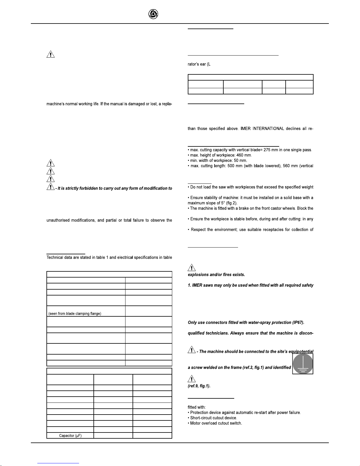
1. TECHNICAL DATA
2.
Table 1 - TECHNICAL DATA
Model
Masonry 700
Blade diameter
700 mm
Blade mounting hole
25,4 mm
Blade rpm (220V/60Hz) single-phase
Blade rpm (220V/60Hz) three-phase
1220 rpm
1710 rpm
Blade rotation direction
clockwise
Motor rating 220V/60Hz single-phase
Motor rating 220V/60Hz three-phase
4 kW
5.5kW
Cutting table dimension
490x660 mm
Overall dimensions
(width x length x height)
850x1550x1600 mm
Overall dimensions for transport
(width x length x height)
850x1550x1600 mm
Sawing machine operating weight 285 Kg
Weight for transport
202 Kg
Table 2
Feature
Motor (220V/60Hz)
three-phase
Motor (220V/60Hz)
single-phase
Power (kW)
5.5
4
Rated voltage (V)
220 220
Frequency (Hz)
60 60
Absorbed current
(A)
22
23.2
rpm
1710 1220
Service type
S1 S1
Insulation category
F F
Protection category
IP55 IP55
180
2. DESIGN STANDARDS
The MASONRY 700 sawing machine has been designed and manu-
factured in accordance with the following standards: EN 12100-1-2; EN
12418 and meets directives 89/336/EEC; 98/37/CE.
3. SOUND PRESSURE LEVEL AND VIBRATIONS
Table 3 shows the sound pressure level measured loadless at the ope-
PA
) and of the vibrations transmitted during operation.
Table 3
Model
Type of motor
L
pA
A
eq
Masonry 700
Electric 95 dB
2.33 m/s
2
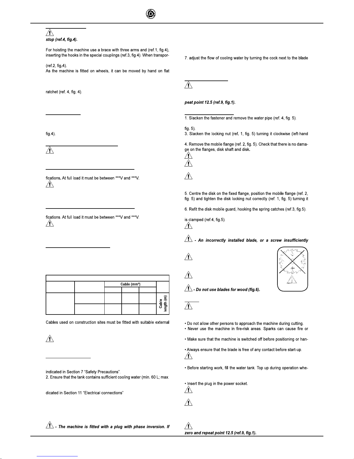
4. CUTTING SPECIFICATIONS
This saw model has been specially designed for cutting stone, ceramics,
marble, granite, concrete and similar materials. Only water-cooled dia-
mond blades with continuous or segmented edges must be used. Under
no circumstances must dry cutting blades be used or materials other
sponsibility for damage caused by improper use of the above machine.
5. CUTTING CAPACITY
(Blade diameter 700 mm)
movement of the disk).
6. WARNING
(max. 40 kg)
wheels with the brake before starting cutting operations.
case, workpieces must not overhang the worktable.
cooling water contaminated with cutting dust.
7. SAFETY PRECAUTIONS
IMER saws are designed for work on construction sites and under con-
ditions of natural light, hence the workplace must be adequately lit (min
500 lux).
- It must never be used in environments where the danger of
devices, which must be in perfect condition.
2. Never use makeshift and/or faulty power cables.
3. Make electrical connections on the construction site where they
will not be subject to damage. Never stand the saw on power sup-
ply cables.
4. Lay power cables in such a way as to prevent water penetration.
5. Repairs to electrical installations must only be carried out by
nected from the power supply and is completely immobile during
repairs and maintenance operations.
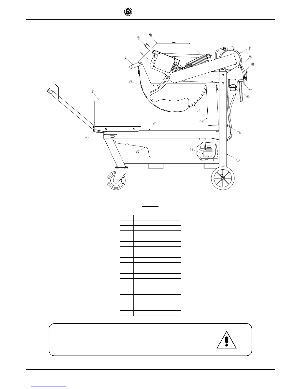
earth system with a copper plait with a minimum cross
section of 16 mm
2
. The connection point is made with
with the earth symbol.
- Stop the saw only by means of the main switch
8. ELECTRICAL SAFETY
The IMER saw meets Std. EN 60204-1, EN 61029-1 and is in particular

IMER U.S.A. Inc.
MASONRY 700
4
9. TRANSPORTATION
- Before removing the panel saw, lock the carriage using the
ting the machine with a fork lift, insert the left fork in the slot provided
surfaces as follows:
1. make sure that the front wheel brakes are released.
2. make sure that the piece holder carriage is clamped with the special
3. pull the machine by hand using the piece holder carriage grip; move-
ment (also round corners) is facilitated by the front castor wheels.
10. INSTALLATION
1. Install the machine on a completely even and stable surface.
2. Block the front wheels with the brakes.
3. Release the carriage from the lever that secures it to the frame (ref.4,
11. ELECTRICAL MAINS CONNECTION
- Make certain that a residual current device and miniature
circuit breaker are installed on the electrical power line.
11.1 Connecting versions with motor 115V/60Hz
Ensure that the supply voltage corresponds to machine dataplate speci-
- To supply the machine it is necessary to use a 2-pole +
ground cable in order to ensure the machine's connection to the
site's equipotential system.
11.2 Connecting versions with motor 220V/60Hz
Ensure that the supply voltage corresponds to machine dataplate speci-
- To supply the machine it is necessary to use a 3-pole +
ground cable in order to ensure the machine's connection to the
site's equipotential system.
11.3 Sizing the power supply cable
The power supply line must be suitably sized to prevent voltage drops.
Do not use cable winders. The electric cable wire size must take into
account the operating currents and length of the line to avoid excessive
voltage drops (table 4).
Table 4
Model
Type of motor
1.5 2.5 4.0
Masonry 700
Single-phase
Masonry 700
Three-phase
220 V
23.2 A
0 - 12
13 - 24 25 - 50
220 V
22 A
0 - 12
13 - 24 25 - 50
sheathing that is resistant to wear, crushing and extreme weather condi-
tions (for example H07RN-F).
- All power supply installations must comply with CEI 64-8
standards (harmonised document CENELEC HD384).
12. MACHINE START-UP
Before connecting the machine to the power supply:
1. Ensure that the metal structure is connected to an earthing plant as
90 L).
3. Ensure that the power circuit corresponds to the requirements as in-
4. Connect the machine to the power supply
5. Turn the start-stop selector to the start position (star connection). Wait
for 5 sec. and turn to the running position (delta connection).
6. Check that the direction of blade rotation corresponds to that indica-
ted by the arrow on the blade guard.
the direction of rotation of the disk is the opposite of the arrow on
the protective guard, disconnect the power socket from the plug
on the machine and invert a phase. To do this, exchange the two
mobile terminals on the poles using a screwdriver. This operation
is carried out without removing the plug working on the rotary ele-
ment that holds the mobile poles.
guard (do not perform cutting without water).
8. If all is in order, proceed with cutting.
13. EMERGENCY STOP
- In the case of an emergency, stop the machine pressing the
special red mushroom button. To start again, reset the mushroom
button turning it clockwise and turn the selector to zero, then re-
14. BLADE INSTALLATION
2.Release the spring catches clamping the disk mobile guard (ref. 3,
thread).
- Never use worn blades or blades with missing segments.
- Only use blades that are designed for the number of revolu-
tions indicated on the machine rating plate.
- Check that the direction of rotation of the disk is as shown
on the disk guard.
counter-clockwise (left-hand thread).
7. Put the water pipe back in place and tighten the fastener until the pipe
Fig. 6
- Ensure that the blade guard (ref.3) is locked securely into
position.
tightened can provoke damage to the machine
or injury to persons.
- Note that the blade must have an external
diameter of 700 mm, a central hole diameter of
25.4 mm and max. thickness of 4 mm.
- Check that the blade to be used is suitable
for the material to be cut.
15. USE
- Leave a space of 150 cm around the machine to operate in
full safety.
explosions.
dling.
- Ensure correct installation of all protective devices.
never necessary: N.B. the pump suction hose must always remain im-
mersed in water.
- For safety purposes the removal of protective guards from
the machine is strictly prohibited.
- The machine is protected against overload: this protection
triggers stopping the machine, after which the time necessary for
the overload to cool must pass before it is possible to restart the
machine.
- To resume work after a voltage cut-off, turn the selector to

IMER U.S.A. Inc.
MASONRY 700
5
15.1 Vertical disk movement
- Always switch off the machine before carrying out blade
adjustment.
the required height from the cutting table and tighten the clamping lever
starting to work.
15.2 Cutting
For safe use of the machine when cutting, push the carriage forwards
as the cut advances, placing your hands to the two sides of the carriage.
Never push directly on the piece to be cut.
- Check that the blade is aligned with the cutting line.
against the stop.
2. Start the engine.
3. Wait until the water reaches the blade.
4. Begin cutting.
5. Horizontal cutting movement is carried out by pulling the carriage
towards the blade.
- As cutting thickness increases, the blade is subjected
to greater stress. To avoid overloading the engine, the operator
should continually check blade feed speed. The speed will also
depend on the characteristics of the material being cut (hardness,
toughness etc.).
15.3.1 Cutting downwards from above
Position the piece to be cut. Start the sawing machine and start cutting
15.3.2 Changing the disk
For changing the disk, please refer to paragraph 4.
16. USING 650 DIAMETER CUTTING WHEEL
ration requires adjustment of the cutting head stroke, which is set by the
manufacturer for a 700 mm diameter disk. If not carried out properly, this
adjustment can damage the machine and cause hazard for persons, it
Proceed as follows:
1. Make sure that the machine is disconnected from the power supply.
2. Fit the 650 mm diameter disk according to the procedure described
in paragraph 14.
4. Lower the cutting head until the disk is in the best cutting position (the
disk outside diameter should protrude 15 mm from the cutting surface).
5. Turn the cam until locking the cutting head and tighten the bolt.
At this point, the cutting head is adjusted for a 650 mm diameter disk.
repeated restoring the original setting. If adjustment is not carried
out, the 700 mm disk would interfere with the piece holder carriage
structure and damage it with the risk of breakage.
- Note that the blade must have an external diameter of 650
mm, a central hole diameter of 25.4 mm and max. thickness of 4
mm.
17. MAINTENANCE
cians and only after the motor has been switched off.
- Always keep the guards in proper working order and free
from damage.Take particular care to ensure that the blade guards
- As there is the continuous risk of inadvertent damage to the
electric cables, these must be checked regularly each time before
the machine is used.
changing them when damaged.
Never leave the machine outdoors: it must be sheltered from the wea-
ther.
Below is a list of the cleaning operations that must be carried out at the
end of every shift.
17.1 Tank cleaning
Empty the tank by removing the drain plug. Remove cutting residue
using a jet of water.
Empty the drum opening the drum cap from right or left side.
17.3 Work surface cleaning
Always keep work surfaces clean. Residual dirt can impair cutting pre-
cision.
17.4 Guide rail cleaning
It is good practice to remove all traces of dirt from the guides.
17.5 Cleaning and maintenance of cooling circuit
If water does not reach the blade stop the machine immediately to avoid
blade damage.
If necessary, after disconnecting the machine from the power supply
17.6 Tensioning the drive belt
1. Switch off the electric motor and remove the plug from the power
supply.
2. Unscrew the 4 screws that secure the movable belt guard (ref.1,
blade support.
4. Tension the belt using the nut (ref.3): applying a force of about F=6
Kg to the centre of the free section of the belt, the arrow should be about
alignment of the motor pulley and the blade pulley
- To avoid shortening the life of the belt, the bearings and the
blade shaft, do not overtension the belt. Finally, check the two pul-
leys are aligned.
17.7 Changing the drive belt
1. Switch off the electric motor and disconnect the plug.
disk holder arm.
with the new one.
is correct, applying a force of approx. F=6 Kg at the centre of the free
of the motor pulley and that of the disk.
17.8 Repairs
- Before carrying out any maintenance operations, switch off
the machine, and remove the plug from the power socket.
- If the guards are removed to carry out repairs, they must be
Only use genuine IMER spare parts and do not modify them.

IMER U.S.A. Inc.
MASONRY 700
6
18. RESIDUAL RISKS AND SAFETY SIGNS
Although the sawing machine has been manufactured fully in complian-
ce with current regulations, residual risks exist that cannot be eliminated
and involve the use of appropriate individual protection devices. Ade-
the behaviour to be followed.
NOISE RISK
Ear protection must be worn
RISK OF INJURY TO THE HANDS
Safety gloves must be worn
RISK OF INJURY TO THE EYES
Eye protection must be worn
ABNORMAL USE RISK
Reading the manual before use is compulsory
Cutting with water is compulsory
RISK OF DRAGGING, ABRASION AND CUTTING
Do not remove the guards
Do not touch transmission components
Danger cutoff
RISK OF ELECTROCUTION
Danger electricity
Please be reminded that checking the use of IPDs is delegated to the
employer.
19. TROUBLESHOOTING
- CAUTION!!! All maintenance operations must be performed
exclusively with the machine switched off, with the selector set to
Fault
Cause
Remedy
Motor does not start
when switch is turned
Defective power cable
Check power
cables *
Plug not inserted in
socket correctly
Ensure correct
connection
Power cable from plug to
control panel detached
Remake the
connection *
Loose wire inside motor
circuit board
Remake the
connection *
A wire has become
disconnected inside the
panel
Remake the
connection *
Faulty main switch
Replace switch
A fuse has blown
Replace the fuse *
The overload safety
device has been
activated
Wait for a few
minutes and then
try restarting the
machine
Horizontal carriage
movement not
smooth
Guide rails dirty
Clean the guide rails
Lack of cooling water
supply to blade
Refer to section "cleaning and maintenance of
cooling circuit" (chapter 17.5)
Blade does not cut
Blade is worn
Fit new blade
Drive belt not tensioned
Tension the belt
Motor starts but
blade does not rotate
Belt is broken Replace drive belt
* Operation to be carried out by an electrician

IMER U.S.A. Inc.
MASONRY 700
7
FIG. 2 FIG. 4
FIG. 5 FIG. 7
FIG. 8 FIG. 9

IMER U.S.A. Inc.
MASONRY 700
8

IMER U.S.A. Inc.
MASONRY 700
9
TAV.1 - MACHINE STRUCTURE
REF.
CODE
DESCRIPTION
NOTES
1
1207088
OIL SEAL RING
ADT D.45X62X8
2
1224113
WASHER
D.10X50X3 Z
3
1283984
NUT
PG 21
4
2211150
WHEEL
5
2213840
FORK
1676 M12X62 Z
6
2218075
VALVE
7
2222007
BOLT
TE 8.8 5739 M12X35 Z
8
2222021
BOLT
TEFR 8.8 5739 M6X16 Z
9
2222036
BOLT
TE 8.8 5739 M12X40 Z
10
2222050
BOLT
TE 8.8 5739 M12X45 Z
11
2222054
BOLT
TE 8.8 5739 M12X80 Z
12
2222073
BOLT
TE 8.8 5739 M10X35 Z
13
2222076
BOLT
TE 8.8 5739 M8X25 Z
14
2222077
BOLT
TE 8.8 5739 M10X20 Z
15
2222110
BOLT
TE 8.8 5737 M8X80 Z
16
2222176
BOLT
TE 8.8 5737 M8X50 Z
17
2222420
BOLT
AUT. TE 6950 D.4,8X13 Z
18
2222430
BOLT
AUTOF. TC 7971 4.8X9.5
19
2222449
BOLT
AUTOF. TC 6954 3.5X19
20
2222530
BOLT
TCEI 5931 M8X35 Z
21
2223570
NUT
5588 M8 Z
22
2223700
NUT
5588 M12 Z
23
2223920
SELF LOCKING NUT
AUTOBL. M10 7474
24
2223921
SELF LOCKING NUT
AUTOBL. M12 7474
25
2223923
SELF LOCKING NUT
AUTOBL. M8 7473
26
2223927
SELF LOCKING NUT
AUTOBL. M5
27
2224006
THREADED INSERT
28
2224140
WASHER
6593 D.8X18 Z
29
2224204
WASHER
6593 D.8X24 Z
30
2224340
WASHER
6592 D.10X21 Z
31
2224430
WASHER
6593 D.14X36 Z
32
2224528
WASHER
D.5X15 Z
33
2224531
WASHER
D.6X18 Z
34
2226700
SPLIT PIN
35
2226778
ELBOWN
F.3/8" D.10 RO150
36
2227240
OIL SEAL RING
7435 E/30
37
2227300
OIL SEAL RING
3653 E/28
38
2228738
PIN
1707 D.10X14
39
2229350
KEY
8X7X35
40
2230550
GREASER
1/8 DIRITTO SGS - 196
41
2235428
CONICAL CAP
42
2241574
KEY
43
2288810
RIVET
44
2288887
KNOB
45
2292355
Y DEVIATION
46
2292356
ANTI-FREEZE HOOSE
47
2292356
ANTI-FREEZE HOOSE
48
2292365
ANTI-FREEZE HOOSE
49
2292365
ANTI-FREEZE HOOSE
50
3201163
NUT
5589 M18
51
3201503
CABLE CLAMP
HSK-K PG21
52
3203921
BOLT
TC PH M5X10 N
53
3204420
CAP
54
3204945
BEARING
608 2RS1
55
3206079
KNOB
56
3206722
KEY
8X7X30
57
3206973
LEVER
58
3207152
BOLT
TCB 7687 M5X20
59
3207393
SPACER BRACKET
60
3207397
WHEEL
61
3208455
BOLT
TTDE M10X35 5732 Z
62
3208726
WATER PUMP
63
3210411
SPACER BRACKET
64
3210576
WASHER
D.8.4X17X1.5
65
3210623
SELF LOCKING NUT
M8 7474
66
3210646
CAP
67
3211038
WASHER
6592 D.13X24 Z
TAV.1 - MACHINE STRUCTURE
REF.
CODE
DESCRIPTION
NOTES
68
3224476
FRAME
69
3224479
CUTTING HEAD
GROUP
70
3224482
BLADE SHAFT
71
3224483
INNER FLANGE
72
3224484
OUTER FLANGE
73
3224486
3230340
PULLEY
THREE-PHASE
SINGLE-PHASE
74
3224510
DISC COVER
75
3224513
GUARD
76
3224514
PLATE
77
3224565
SPACER BRACKET
78
3224566
SPACER BRACKET
79
3234187
CARRIAGE
80
3224626
BOLT
TTCQ 5732-65 M8X25 Z
81
3224680
SPACER BRACKET
82
3224705
GUIDE BAR
83
3224740
GUARD
84
3224741
GUARD
85
3224814
CAP
86
3225043
PROTECTION
87
3225543
HANDGRIP
88
3225548
BLADE GUARD
ROTATION ROD
89
3225551
PLATE
90
3228124
3230332
JUNCTION BOX
THREE-PHASE
SINGLE-PHASE
91
3228123
3230330
MOTOR
THREE-PHASE
SINGLE-PHASE
92
3225564
BELT
93
3225642
DRUM
94
3225955
CAM
95
3225956
SPACER
96
3225984
PLUG
97
3225993
SUPPORT
98
3225994
SUPPORT
99
3225996
SPRING
100
3225997
WHEEL
101
3226001
HANDGRIP
102
3226002
WASHER
PS 13X19X1
103
3226003
FRONT HEAD
PROTECTION CASING
104
3226004
REAR HEAD
PROTECTION CASING
105
3226009
REAR SPLASHGUARD
SUPPORT
106
3226015
OIL SEAL RING
7435 E/75
107
3226028
NUT
5589 M24X2 SIN Z
108
3226034
SPACER BRACKET
109
3226035
SPACER BRACKET
110
3226036
CUTTING WHEEL RH
GUARD
111
3226037
CUTTING WHEEL LH
GUARD
112
3226039
TROLLEY CLAMPING
113
3226040
BOLT
TE 8.8 5737 M18X200 Z
114
3226043
REAR SPLASHGUARD
115
3226044
PLATE
116
2204220
BEARING
THREE-PHASE
117
3228125
3230465
PLUG
THREE-PHASE
SINGLE-PHASE
118
3228471
RH SPLASHGUARD
OPTIONAL
119
3228472
LH SPLASHGUARD
OPTIONAL
120
3228543
SIDE SPLASHGUARD
SUPPORT
OPTIONAL
121
3224486
3230342
PULLEY
THREE-PHASE
SINGLE-PHASE
122
3210448
CAPACITOR

IMER U.S.A. Inc.
MASONRY 700
10
TAV.2 3228124 ELECTRIC PANEL THREE-PHASE
REF.
CODE
DESCRIPTION
1
3201217
CABLE CLAMP
2
3201442
CABLE CLAMP
3
3201503
CABLE CLAMP
4
3226296
JUNCTION BOX
5
3228375
SAFETY CATCH BUTTON
6
3226298
SWITCH
7
3228376
CONTACTOR
8
3228374
MAGNETOTHERMAL MOTOR OVERLOAD
PROTECTION CIRCUIT BREAKER
9
3228841
CONTROL CONTACTS
10
3228840
CONTROL RELAY
Table 4 MOBILE SOCKET
CODE
3230464
SINGLE-PHASE
CODE
3228456
THREE-PHASE

IMER U.S.A. Inc.
MASONRY 700
11
3230332
TAV.5 ELECTRIC PANEL
SINGLE PHASE
RIF.
COD.
1
3201217
CABLE CLAMP
2
3201442
CABLE CLAMP
3
3201503
CABLE CLAMP
4
3230333
ELECTRIC BOARD
5
3207929
SUPPORT
6
3207928
START AND STOP SWITCH
7
3207924
THERMO-MAGNETIC
CUTOUT SWITCH
8
3207922
COIL
RIF.
ID
CUTOUT SWITCH 30 mA
I1
THERMO MAGNETIC
CUTOUT SWITCH 20-25A
U <
MINIMUM VOLTAGE COIL
TM1
THERMAL PAD MAIN
ENGINE
F1
FUSEHOLDER 6,3x32 +
FUSE 1A
F2
FUSEHOLDER 6,3x32 +
FUSE 1A
C1

IMER U.S.A. Inc.
MASONRY 700
12

IMER U.S.A. Inc.
MASONRY 700
13
ONE YEAR WARRANTY
We warrant to the original purchaser that the IMER equipment described herein (the "equi-
pment") shall be free from defects in material and workmanship under normal use and
service for which it was intended for a period of one (1) year from the date of purchase by
the original purchaser.
Our obbligation under this warranty is expressely limited to replacing or repairing, free of
charge, F.O.B. our designated service facility, such part or parts of the equipment as our
inspection shall disclose to be defective. Parts such as engines, motors, pumps, valves,
electric motors, etc. furnished by us but not manifactured by us will carry only the warranty
of the manifacturer. Transportation charges or duties shall be borne by the purchaser. This
shall be the limit of our liability with respect to the quality of the equipment.
This warranty shall not apply to any equipment, or parts thereof, which has been damaged
by reason of accident, negligence, unreasonable use, faulty repairs, or which has not been
mantained and operated in accordance with our printed instructions for our equipment.
Further, this warranty is void if the equipment, or any of its components, is altered or modi-
THIS WARRANTY IS EXPRESSLY IN LIEU OF ALL OTHER WARRANTIES, EXPRES-
SED OR IMPLIED, INCLUDING ANY IMPLIED WARRANTY OF MERCHANTABILITY OF
FITNESS FOR A PARTICULAR PURPOSE.
We make no other warranty, representation or guarantee, nor is anyone authorized to
make one on our behalf. We shall not be liable for any consequential damage of any kind,
including loss or damage resulting, directly or indirectly, from the use or loss of use of the
machine. Without limiting the generality of the foregoing, this exclusion from liability em-
braces the purchase's expenses for downtime, damages for which the purchaser may be
liable to other persons, damages to property, and injury or death of any persons.
This warranty shall not be deemed to cover maintenance parts, including but not limited
liability whatsoever.
IMER
U.S.A. Inc.
221 Westhampton Place
Capitol Heights, MD 20743
Ph. 301.336.3700
Fax 301.336.6687
Toll Free: 800.275.5463
www.imerusa.com
Table of contents
Other IMER Saw manuals