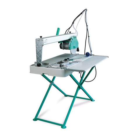
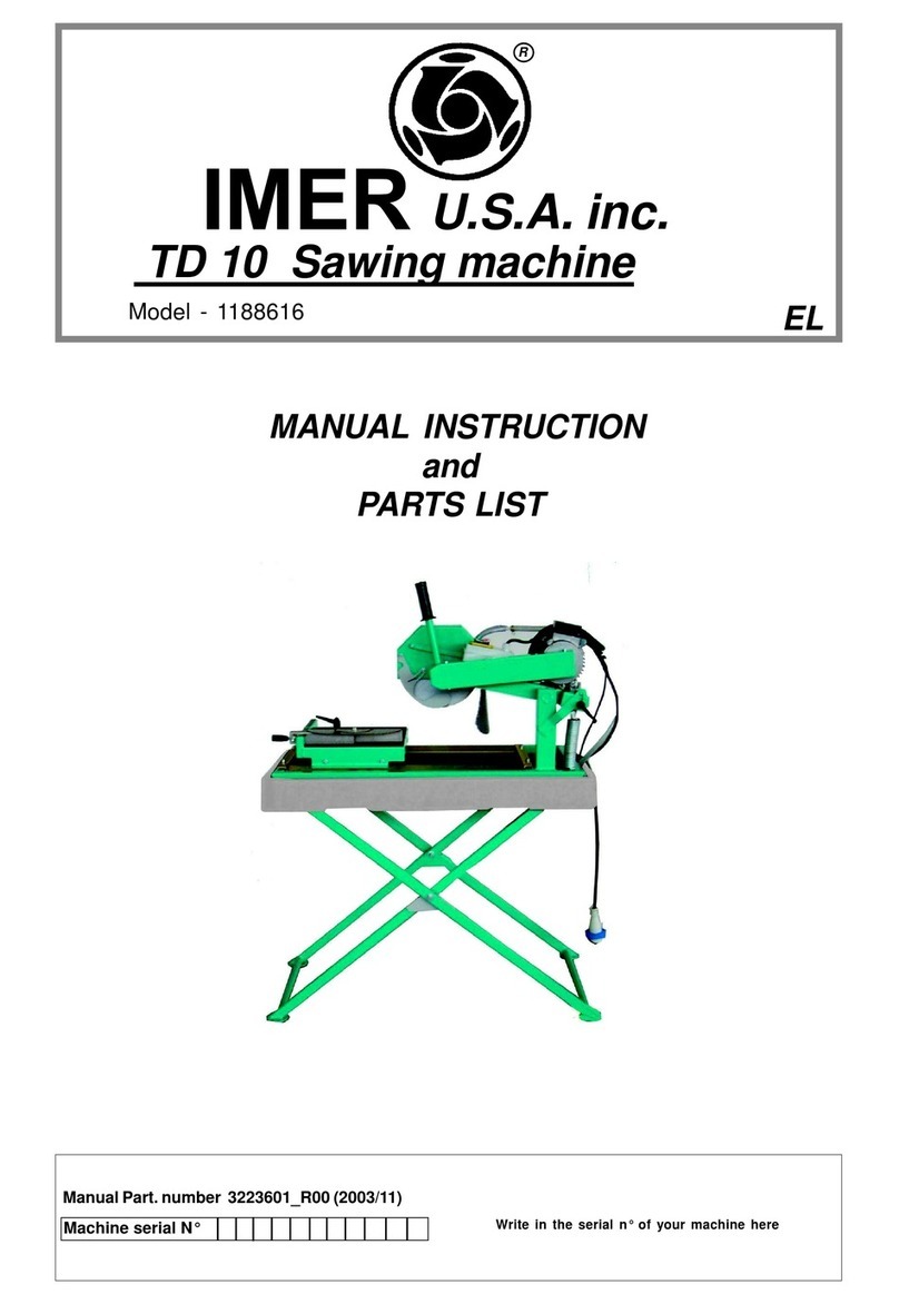
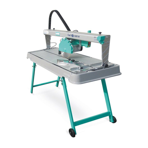
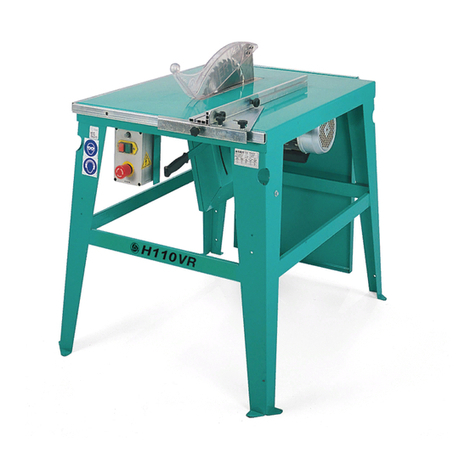
IMER MASONRY 350 Guide

ONE YEAR WARRANTY
Wewarrant tothe original purchaser thatthe IMER equipment described herein
(the "equipment")shall befreefromdefectsin material andworkmanship under
normaluseand serviceforwhich itwas intendedforaperiodofone(1) year
from
thedateofpurchase bytheoriginal purchaser.
Our
obbligation underthis
warranty is
expressely limitedtoreplacingorrepairing,
free ofcharge, F.O.B.our designated service facility, such partorparts of the
equipmentasourinspectionshalldisclosetobedefective. Partssuchasengines,
motors, pumps,valves, electric motors,etc.furnished byusbutnotmanifactured
byuswill carryonlythewarranty
ofthe manifacturer.Transportation charges or
duties shallbeborne
bythepurchaser.Thisshallbethe limit ofourliability with
respect tothequality
ofthe equipment.
Thiswarranty shall notapply
toanyequipment, orpartsthereof, whichhas been
damaged byreasonofaccident, negligence, unreasonableuse, faultyrepairs,or
which has not been mantained and operated in accordance with our printed
instructionsforourequipment. Further,thiswarranty
isvoidiftheequipment, or
anyofits components, isaltered ormodified in anyway.
THIS WARRANTY IS EXPRESSLY IN LIEU OF ALL OTHER WARRANTIES,
EXPRESSEDOR IMPLIED, INCLUDING ANY IMPLIED WARRANTY OF
MERCHANTABILITYOF FITNESSFORAPARTICULARPURPOSE.
Wemake nootherwarranty, representation
or
guarantee,noris
anyoneauthorized
tomake oneonourbehalf.Weshallnotbeliablefor
anyconsequentialdamageof
anykind, including loss or
damage resulting,directlyor
indirectly,fromthe useor
loss ofuseofthe machine. Withoutlimiting the generality oftheforegoing, this
exclusionfromliabilityembracesthepurchase'sexpenses
for
downtime,damages
forwhichthepurchaser maybeliabletoother
persons,damages toproperty,and
injuryordeath ofanypersons.
Thiswarranty shall notbedeemed tocover maintenance parts, including butnot
limitedtoblades, belts, hoses, hydraulic oil orfilters, forwhich weshallhave no
responsability orliabilitywhatsoever.
IMER U.S.A., Inc.
207 LawrenceAvenue
South San Fan
cisco,California94080
(650) 872-2200
PDF compression, OCR, web-optimization with CVISION's PdfCompressor

IMER U.S.A. Inc.
MASONRY350
Fig. 1 MACHINELAY-OUT
1
2 TELESCOPICLEG
SPRAYGUARD
3 MOTOR
BLADESUPPORT
ARM
5 WATERPUMP
6 GUIDE
7 MAINSWITCH
8 WORKTABLE
9 WATERTANK
lQ BLADE GUARD
11 EARTHING SCREW
'2 HEADBLOCKAGE
DearCustomei
Congratulations on
your
choiceof
purchase:
IMERsawsarctheresultof
years
of
expenence andis
equipped
t'r4ThaiYelatesttechnalinnovations.
WORKINGINSAFETY
Toworkincomnletesafelv.readthefollowinainstructionscarefully.
-ThisOPERATION
AND
MAINTENANCEmanualmustbe
kept
onsite
by
the
person
incharge, e.g.theSITE
FOREMAN,
andmust
always
be
availableforconsultation.
-
Themanualistobeconsidered
integral part
ofthemachineandmust
be
kept
forfuturereference
(EN292/2)
untilthemachineis
disposed
of.
Ifthemanualis
damaged
or
lost,
a
replacementmaybe
requested from
thesawmanufacturer.
-Themanualcontains
important
information regarding
sitepreparation,
machine
use,maintenance
procedures, andrequests
for
spareparts.
Nevertheless,
theinstallerandthe
operator
mustbothhaveadequate
experience
andknowledge
ofthemachine
prior
touse.
-To
guaranteecompletesafety
oftheoperator, safe
operation
andlong
life of
equipment,
followtheinstructions
inthismanualcarefully, and
observeall
safety
standards
currentlyinforcefortheprevention
ofaccidents
atwork
(useofsafetyfootwearandgloves
in
acconiancewith3.1.N°3073
of
30/11/92).
times. Safetyglasses ora
protective
visormustbewornatall
MAKESURETHATSIGNSARELEGIBLE.
Itis
strictly
forbiddento
canyoutany
formofmodification
tothesteelstructureor
workingparts
ofthemachine.
-
IMERINTERNATIONALdeclinesall
responsibility
for
non-compliance
withlawsandstandards
governing
theuseofthis
equipment, in
particular;
improper
use,defective powersupply,lackof
maintenance, unauthorised
modifications,
and
partial
ortotalfailuretoobservetheinstrudionscontained
inthismanual.
1.DESIGNSTANDARDS
MASONRY350sawsare
designed
andmanufactured
according
tothe
following standards:I.E.C.
34.4;
EN
392(91/368CEE);
CEIEN60204.
2.NOISEEMISSIONLEVEL
Operatorexposure tosoundemissionlevels(continuous
sound
pressure
levels
equal
to"A"
weighting); theMASONRY350sawnoiseemission
level
duringcutting
is93
dB(A)
withcontinuous
rim
blade.
3.CUT11NGSPECIFICA17ONS
Thissawmodelhasbeen
speciallydesignedbyIMERforcutting
stone,
ceramics,marble, granite, concreteandsimilarmaterials. Onlywater-
2
cooleddiamondbladeswithcontinuousor
segmentededges
mustbe
used.Undernocircumstancesmust dry cuffingbladesbe used or
materialsotherthanthose
specified
above.IMERINTERNATIONAL
declinesall responsibility for
damagecaused
byimproper
useofthe
abovemachine.
TECHNICALDATA Masonry350
lade rpm rpm 2040/2150
lade diameter inc 14"
lade mounting
hole inc 1"
lotorrating Hp 1,5/3,0
lotorrpm rpm 3260I3450
;uttingtabledimensions inc 20 x 17"
)veralldimensions inc 43"x34"x47"
)veralldimensionsfor
ransport ft ,,
52 x30 x32
Veight lb 255
Veight
for
transport lb 300
lade rotation
irection(seen
from
lade clampingflange) ANTI -CLOCKWISE
urrent A 13,4111
Voltage V 1151230
requency Hz 60
4.CUT17NGCAPACITY
-max.cutting capacity
withverticalblade:5°
-max.cutting capacity
withbladeat45°:3"
-mm.dimensionsof
workpiece(width):
2'
-max. dimensionsof
workpiece(width):
20'
Vertical bladelowered:
wxhxl
mm(inc) =500(20")x25(1")x480(19')
=500(20")x60(3")x450(18")
=500(20")x120(5")x400(16")
Verticalbladeraised cutting
withbladelowered fromabove:
wxhxlmm(inc) =
500(20")x120(5")
x
450(16")
Bladeat45°:
wxhxlmm(inc) =
500(20")x
30(2")
x480
(19")
5.WARMNG
-Donotloadthesawwith
workpieces
thatexceedthe
specifiedweight
(max.
90
Ib)
-
Ensure
stability ofmachineand
workpiecebefore,duringorattercutting.
Installsupplementarysupportsurfaces atthesame heightasthe
worktable.
-Respect
the
environment;
usesuitable
receptacles
forcollectionof
Fig. I -Machine Lay-out
Payspecialattention to
warningsbearing the
following symboL
PDF compression, OCR, web-optimization with CVISION's PdfCompressor

IMERsaws
comply
withEN
60204-1;
andarefittedwith:
-
protection
device
against
automaticre-startafter
powerfailure.
-
Short-circuit cutoutdevice
-
Motoroverloadcutoutswitch
IMER U.S.A. Inc.
MASONRY350
cooling
watercontaminated withcutting
dust.
6. SAFETYPRECAUTIONS
IMERsaws are designedforworkon construction sites and under
conditionsofnatural
light
andin
workshops
underconditionsofnatural
orartificiallightingofminimum500LUX.
Themachinemustneverbe usedinenvironments
subject
torisksof
explosionand/or undergroundsites.
-IMERsawsmayonly
beusedwhenfittedwithall
requiredsafetydevices
which mustbe in perfect
condition.
-Neverusemakeshift and/or faultypower
cables.
-Makeelectrical connections on theconstruction site wheretheywill
notbesubject
to
damage. Never stand thesawonpowersupply
cables.
-Laypowercableswherethey arenot
subjectto risk of
damageor
contactofconnectors withwater. Onlyuse connectors fittedwith water-
sprayprotection (lP55).
-Repairs to electrical installations mustonly
becarried outbyqualified
technicians. Always
ensurethatthemachine is disconnected fromthe
powersupply
andis
completely immobileduringrepairsandmaintenance
operations.
2
-Ensurethatthetankcontainssufficient
cooling
water.
3-Ensurethatthe
power
circuitcorresponds
tothe
requirements
as
indicated inSection11 "Electrical connections"
4-Connectthemachinetothe
powersupply
5-Settheswitchto"1"andwhenthemotorisstartedreturnto
position
"0"afterensuringthat
coolingwaterreachestheblade.
6-Check thatthedirection ofbladerotation corresponds tothat
indicated by
thearrowontheblade
guard.
7-Ifallisinorder,
proceed
withcutting.
12.EMERGENCYSTOP
-Intheeventof
emergency,stop
themachine
bypressing
the
stop
controlswitch.
Lts -
Themotorisfittedwithanoveiloadcutoutdevice.ffthe
motoroverheats,itwill
automatically
shutdown.Allowmotorto
coolbeforere-starting.
-Themotoris
protectedagainst
automaticre-startafter
intem,ptionsduetopowerfailure. Toresume
operation,
when
power
is
re-connected,
repeat
machinestart-upprocedure.
-Connectthemachinetoasuitable
equipotentialearthing
plant
ontheconstruction site with wirebraidofminimum 16
mm2f's
section.Theconnection
point
isidentified
bya
screwweldedtothe1
frame(see Fig.1),
andonthe
ratingplateby
the
earthingsymbol. 13.BLADEINSTALLATION(Ref.Fia.3)
-
Stop
thesaw
onlybymeans
ofthemainswitch.
The
symbolshownonthelabel
(seeleft)
indicatesthe
' Ianing
"ENSURE
ALLPROTECTIONDEVICES
ARE
INSTALLEDANDINPERFECTCONDITIONBEFORE
/ SWITCHINGONTHEMACHINE"
7.ELECTRICALSAFETY
8.TRANSPORTATION
(Ref.Fig2)
Lts WARNING!Always
removethe
plug
fromthe
powersocket
before
moving
the
saw,andlockhead
supportcaniage
movement
bymeans
oftherelativeknob
(ref.3).To
transport
themachineuse
slingingequipment with4ropelegs,fixing
thehookstotherelative
attachments
9.INSTALLATION(Ref.Fip.2)
Fixthehookstotherelative attachmentsonthemachineand liftthe
machineoutofitspackage.
-Unlockthelegsbysliding
out
splitpins(ref.2)
andpins(ref.1).
-Lockthe
legs
at
workingheight. Refitthe
pins
inthe
legsupports
and
insertthe
splitpins.
-
Installthemachineona
completely
evenandstablesurface.
10.ELECTRICALCONNECTION
By
meansofahexwrench
no.10,
removefrontscrews
(ref.1)
andloosen
theothertwoscrews
(ref.2)
whichsecuretheblade
guard.
Turnthe
guard
clockwiseto
gain
accesstothe
securing
screw
(ref.4).Useahexwrench
no.13toremovethescrew(tumanti-clockwise). Removethemobile
flange
andcheckthatthe
flanges, discshaftandbladearenot
damaged.
-
Neverusewornblades.
-Only
usebladesthatare
designed
forthenumberof
revolutionsindicatedon
the
machine
ratingplate.
-
Checkthatbladerotationconsponds
tothatindicated
ontheblade
guard.
Centretheblade
against
thefixed
flange,position
themobile
flange
and
tightenthesecuringscrewbymeans ofa hex wrenchno. 13(turn
clockwise).
Returnthe
guard
toits
originalposition
andlock
by
meansof
screws
(ref.1 and2).
-Ensurethattheblade
guardislocked
securely
into
position. -WARNING!An incorrectly
installed blade, orascrew
insufficientlytightenedcan
provokedamage
tothemachineor
injury
to
persons.
-Notethattheblademusthave anextemal diameterof
350mm., acentralholediameterof1"mmandmax. thickness of
3/25. -
Checkthatthebladetobeusedissuitableforthematerial
tobecut.
14.USE
Leavea
space
of5ftaroundthemachine to
operate
in
fufisafety.
-Donotallowotherpersons
to
approach
themachine
duringcutting.
-Neverusethemachinein fire-riskareas.Sparkscan causefireor
explosions.
-
Makesurethatthemachineisswitched offbeforepositioningor
handling.
-
Always
ensurethatthebladeisfreeof
any
contactbefore
start-up.
-Ensurecorrectinstallation ofall
protective
devices.
-Ensurethatbladerotation
correspondstotheindications
ontheblade
guard.
Beforestarting
work,
fillthewatertank.
Topup
during
operation whenever
necessary:N.B.thepumpsuction hosemust always
remain
immersed inwater.
Insertthe
plug
inthe
power
socket.
WARNING!
Forsafetypurposes theremoval ofprotective
guards
from
themachineis
strictlyprohibited.
Themachineis
protectedagainst
overload.
WARNING!Always
switchoffthemachinebeforecan
ying
outblade
adjustment.
14.1VERTICALBLADEMOVEMENT(RefFig.4)
Toraiseorlowerthe
blade,slackenknob
(ref.2)byturning
ftanti-clockwise.
Setblade
support(ref.1)tothe
required position
andlockbytightening
theknob
fully(ref.2).
Ensure thatthe
locking
knobistightenedfullybefore
Lts Ensurethatthereisanoverloadcutoutdevicefitted
up-
lineonthe
power
line.If
necessary,installan
IMERquickconnect
residualcurrentcircuitbreaker
(RCCB)(codeno.1169245available
inkitfoimfor
23oVmachines).
Ensurethat themains voltagecorresponds
tothat specified
forthe
machine:230V/6OHz -115V/6OHz.
L1\ All
powersupplyinstallations
must
comply
withCE!64-
8standards (ha,moniseddocumentCENELECHD384).
Theelectrical
power
cablemustbe
suitably
sedtoavoid
voltagedrops.
Cabledrums(with
collector
rings)
mustnotbeused.
Cabledimensionswill
varyaccording tothe
start-up
currentandlength
of
cable.In
general
cablesizesof4mm2aresufficientfor
lengthsup
to160
ft.Afterinstallationalwayscarry
out
voitagetesting
underload
conditions,
bothat
start-up
andduringoperation. During operation,voltagedrops
mustneverexceed5%.Inthecaseof
longer
cablesora
power
supply
network
subject
tovariations, usecableswith a sectionofatleast6
mm2.Cables usedonconstructionsites mustbe fittedwith suitable
external
sheathing
thatisresistantto
wear, crushing andextremeweather
conditions.
11.MACHINESTART-UP
Before
connecting themachinetothe
powersupply:
1-Ensurethatthemetalstructureisconnectedtoanearthing plantas
indicated inSection7
"Safety
Precautions".
3
PDF compression, OCR, web-optimization with CVISION's PdfCompressor

starling wot*
14.2BLADEPOSITIONINGFOR45°CUTS(Ref.Fip.5)
Slackenknob (ref.1);
theblade
supportarm
(ref.2)isunlockedand
socanbesettoitslimit
position,i.e. inclinedat450with respectto
theworktable.Tightentheknobfullyto lock intoposition.
To
bnng
thebladebacktotheverticalposition(pos.O)carly
outtheabove
operations
inreverseorder.
Ensurethatthe
Iockingknob(ref1)
is
tightenedM!ybefore
starling
woi*.
14.3CU7TING
-Beforecutting, checkthatthe
bladeisalignedwith the
cutting
lineandthatthe
locking
knobsare tightenedfully.
Placethe
workpiece
ontheworktable
snuglyagainst
thefenceandstart
up
themotor.
Waituntilthewaterreachesthebladeandbegincutting.
Horizontal cuttingmovementiscaniedout
bypulling
the
caniage
towards
the
operatorby
meansoftherelative handle
(ref.1fig.6).
As
cuttingthicknessincreases,
thebladeis
subjected to
greaterstress.Toavoid
overloadingthe
motorthe
operator
should
continuallycheckbladefeed
speed.The
speedwillalsodependon
thecharactensticsofthematerialbeing
cut
(hardness,toughness
etc.).
14.3.1CUTSWITHBLADELOWEREDFROMABOVE
(RetF,g.8)
Bring
theblade
supportto its highestposition
andlock. Positionthe
workpiece
ontheworktable. Startthe
machine, unlocktheblade
support
andbegin
vertical
cutting
untilthebladereachesitslowest
point. Lock
the
support
oncemoreandproceed
withhorizontal
cutting.
14.3.1BLADECHANGE
To
changethebladerefertosection14.BLADEINSTALLATION.
A MAX 3/16
Donotuseblades forwoodorsegmenteddiskswith
slotswiderthan3/16.
15.MAINTENANCE
-WARNING! Always switchthe machine offand
removetheplugfromthe
power
socketbeforecarrying out
any
maintenance
operations.
-
Always
checkthatthe
protectiveguards
areinthe
correct
position
andin
perfect
condition.
-
Asthereisthecontinuousriskofinadvertentdamage
totheelectriccables,
thesemustbechecked
regularlyeach
timebeforethemachineisused.
-WARNING!If
theelectricmotororcontrol
panel
are
removedfor
maintenance, it's
necessary
to
replace
therelevant
sealsinorder
toguaranty
the
rightdegree
of
protection and
safetyagainstwater
penetration
insidetotheelectriccircuits.
Neverleavethemachineoutinthe
open.Makesurethatitisstored
inashelteredarea away
fromextremeweatherconditions.
Replaceworn or
faultycomponentswith originalspare parts.
15.1TANKCLEANINGONWORKCOMPLETION
On completion ofwork, emptythe tank and remove.Clean
thoroughlytoremovecuttingresidue.
15.2TANKREMOVAL (Ref.Fip.7)
Liftthetank (ref.1)todetach fromitssupports (ref.2)andremove
fromthesideindicated by
thearrow.
15.3WORKSURFACECLEANING
Alwayskeep worksurfaces clean. Residualdirtcanimpair cutting
precision.
15.4GUIDERAIL
CLEANING
Thehorizontal
guide
elementsonthe
carriage
areprotectedagainst
dirt
build-upbyscrapers.Howeverweadvise thoroughcleaningof
the
guide
railstoensure correct
operation.
WARNING! Donotuseanytype
oflubricantonthe
guide
rail.
15.5CLEANINGANDMAINTENANCE OFCOOLINGCIRCUIT
-
Ifwaterdoesnotreachthebladestopthemachineimmediately
to
avoidblade
damage.
-After switching offthemachine ensurethatthewaterlevel is
sufficient.
-Ifnecessary, after disconnecting the machine fromthe power
supply checkthatthe
tap,hoseand pumpfilterarenotblocked
-
If
necessary,
checkthatthe
impellerrotatesfreely(after
extended
periodsof
disuse)
-Ifnecessary,removethepump andcheckthatthe
pump/motor
coupling
isinperfect
condition.
15.6DRIVEBELTREPLACEMENT
-
Disconnectthemachinefromthepower
supply.
-
Removethewaterhoseconnection byloosening thehose
damp
onthe
bladeguard.
-
Removethe
blade,thetwo
flanges, theblade
half-guardsecuringscrews,
the
locking
knob(ref.1,
chart02)and removethebladeexternalhalf-
guard(motorside).
-
Removethebladeshaftwith
pulley
fromthe
bearing (ref.27,drawing 02)
andfitintothe
bearing
ofthe
half-guard previously
removed
(ref.14, chart
02).
-
Fitthenewbeltontothetwo pulleys
andrefitthebelttensioner.
-Refitthesealontheedgeofthe
guardand ensurethatitisingood
conditionandthatthetwolocatingpins
areinthecorrect
position.
-
Refitthe
guardinserting thebladeshaftintothe
bearing (ref.27, chart
02)taking
careto
align
thescrew
(ref.51,drawing02)
locatedontheslot
oftheheadfulcrum(ref.19,drawing02)
with the
lockinghandlehole
(ref.1,drawing02).
-Jointhetwobladehalf-guardsusing
thetwolocatingpins
to
aligncorrectly.
-
Screwinthetwoblade
half-guardsbytighteningdiagonallyopposite
screws
alternately.
-
Screwinandtighten
the
locking handlebefore
installing theblade.
16.TROUBLESHOOTING
N.B.:Beforecarrying
out
any
maintenance operations,
switchoffthe
machine,settheswitchto"O"andremovethe
plug
fromthe
powersocket.
FAULT CAUSE REMEDY
Motordoesnotstart
whenswitchis
turned
-
Defective power
cable
-
Plugnotinserted in
socket
correctly
-
Powercablefrom
plugtocontrol
panel
:ireinside
motorcircuitboard
-
Awirehasbecone
disconnected inside
the
panel
-
Faulty
mainswitch
-Theoverload
safety
devicehasbeen
activated
-Checkpower
cables
-Ensure correct
connection
-Connectcable- re
-Connectwire
-Remake the
connection
-Replaceswitch
-Waitforafewminutes
andthen
tiyrestarting
themachine
Verticalblade
movement not
smooth
-
locking
knobtoo
tight -Slacken knob
Lockingknobsdo
notlock -
threadisworn -Replaceknobs
Bladeinclination
notsmooth -
locking
knobtoo
tight -Slacken knob
Horizontalblade
movement not
smooth
-
locking
knobtoo
tight -Slacken knob
Lackof
cooling
water
supply
to
blade
Refertosection 16.6: "cleaning and
maintenance of
cooling
circuit'
Bladedoesnotcut
-
Incorrect blade
rotation
-
Bladeisworn
-Remove theblade
andrefitinthe
position
asindicated onthe
bladelabel.
-Fitnewblade
Motorstartsbut
bladedoesnot
rotate
Beltisbroken Replace drive
belt, see
Chapter 16.7
IMER U.S.A. Inc.
MASONRY350
4
PDF compression, OCR, web-optimization with CVISION's PdfCompressor

IMER U.S.A. Inc.
'Y MASONRY350
18. SPARE PARTS Allordersforspareparts must indicatethefollowing: 1 -Type
ofmechine.2 - Pertnumber endposition number ofeeoh pert.3 -Serial number end
yeer
ofmanufacture reported
onthe meohinesidenfificetion plate.
SYMBOL:
lntercheoeability(exemple):Poe..1 Rn. 3204530 weeinstelledon machinc,up toN5240endPos.1.1 Rn.3204520installedon machine W 5241 onwards. Pos. 1.1 is
interchangeable ( 9)with Poe. 1.Poe. 1endPoe. 1.1 arenot interchangeable ifthe(Jo symbol appears inthetable.
1 3208421 CARRIAGe
2 2222061 BOLT 5729 M 9x20
3 22225l5 BOLT 5931 M exie
4 3204040 BEARING Eee-2R51
5 2223923 SELFLOCKING NUT M.8
6 3207307 WHEEL
7 2222090 BOLT
e 32e57e2 ouioe BAR
9 3208442 LEFTFCN0CA0HEeIVE
Is 32ee441 1GBHETLF
ENCE AOHESIVE
II 3205581 RUBBER cOAITING
12 3206045 WASHER
13 3206086 PIN
14 3205475 COLLAPSIBLE LOG
lB 3200560 ROTARYBLADE ARM
16 3206096 SUPPORT
17 2223655 NUT 5509MIS
18 3201015 PLUG
19 2222567 SCROW
20 3200609 SPRAYGUARD
21 3200541 FRAME
22 3205526 WATER RUN-OFF TRAY
23 2222425 SCREW AUTOFOR.TE 4,2X13
6
29 2235428 PLUG
26 3206030
3206269 WATER PUMP IISVI6OHz
230VI65Hz
27 2292365 TUBE
29 3205704 BOLT 5737 MISXIOO
29 2223650 NUT 5588MIS
35 3206104 HEAD CLAMP
31 2222146 SCREW 5739MISx30
32 2222120 SCREW 5737MleXeO
33 3200414 LEVER
34 3208429 GONIOMETER
35 3207213 GUIDE BAR SUPPORT
36 3200420 TROLLEYSLIDE
37 2224531 WASHER 8593 OslO
38 2223500 NET 5588 M4
39 3206103 LOCK PLATE
40 3209333 KNOB MO
41 3208429 TROLLEY
CLAM
FWG
42 2222016 SCREW 5739 M8x29
43 2223924 NUT 5088 M6
44 3209332 CAM
45 2222010 SCREW 5931 M5X35
46 2223923 NET MO
1 3204530 Riduttore Reducteur Reducer Untersetzungsgetriebe Reductor 5240
2 3204520 Riduttore Réducteur Reducer Untersetzungsgetriebe Reductor 5241
AKOI4 TAB.2 FRAME ASSEMBLY
RIF. COD. USA DETAILS RIF. COD. USA DETAILS
24 3204818 DRUM
PDF compression, OCR, web-optimization with CVISION's PdfCompressor

AK014 TAB.2MOBILEHEADASSEMBLY *IMER U.S.A. Inc.
MASONRY350
TAB.2
RIF. COD. USA DETAILS
1 2284827 SNOLE
1. 222438 ASI-IER 6593012X25
3 222254 OLT 5931M6X30
4 222304 UT M105721-6S
S 323276 OVER
6 321419 OLT 5737 M1OX5O
.1. 321465 EARING 6000 2R5
6 320391 OLLER 6592 010X20
9 321419 ASHER
10 321419 ELTTENSIONERARM
11 222214 OLT 5737M10X65
12 222392 UT AUT M10 7474
13 321420 PRING
14 320651 EARING 6203 2RS
15 320473 ELT
16 320473 ULLEY
17 320673 LADESHAFT-PULLEY
18 222201 DLT 5739 M6X20
19 323274 EADFULCRUM COUBI
19 320649 EADFULCRUM MASONRY350
20 2204510 EARING 6009 2R5
21 2228820 PN 6x14
22 3204788 PN
23 3204787 PRING
24 3207366 OMPENSATING RING
27 2204540 EARING 6205 2RS
28 3232759 LSEALRING 35X52X7
31 3209687 OLT 5737
U
6X135
32 2224531 ASHER 65930 6X15
33 2223924 NUT AUTOBL.M6
34 3209400 SPRAYGUARD
30 3205635 VALVE
36 3209387 TUBE
37 2222709 BOLT 5739M5X10
38 320938 SUPPORT
41 228482 HANDLE COMBI600-MASONRY
42 222251 BOLT 5931 V8X16
43 3204777 NNERFLANGE
45 320477 OUTERFLANGE
46 22241
47 222201
SASHER
3OLT 65930 8X18
5739 V9X20
49 320940 BLADE COVER
49 2222021 BOLT 5739M6X16
50 320712 LABEL
51 3203914 BOLT TTOM12X90
52 323274 GASKET
53 3206131 WASHER 3545016x35x1,4
54 320940 SUPPORT
55 RIVET
56 SHOCKABSORBER
57 WASHER 659305x15
50 BOLT M6X1OZ
59 WASHER 659206X12.5
12
2j3
II Ei
J)
AKOI4 TAB. 3 ASSEMBLYOFMOTOR
RIR COD. USA DETAILS
1 3214262
22856G1 CAPACITOR 11SV/60F-IZ
23GV/6GHZ
2 3207920 CONTACTOR
3 3207927
3207924 COIL I1SV/00H7
23GV/SGHZ
4 3201503 CABLE-CLAMP
S 3207933 COVER
6 3232743 GASKET
7 3250412 BOLT
8 3207934
3207937 MOTOR 115V/601t
230V/6OHz
9 3205924 LABEL
10 3207929 JUNCTIONBOX
11 3207929 PUSH
12 3232270 GASKET
13 1222252 BOLT
14 3201217 CABLE-CLAMP
15 3207184
3208070 PLUG 11SV/6OHz
230V/6OHz
16 3206171 SWITCHCOVER
17 3206170 WATERPUMPSWITCH
6
7
PDF compression, OCR, web-optimization with CVISION's PdfCompressor

AKOI4 TAB. 4.1 ASSEMBLYOFMOTOR *IMER U.S.A. Inc.
MASONRY350
10 8
15 2Assembly
ofmotor
L428 (TAB.4.1)
19
16
RIF. COD. USA DETAILS
1 3203680
3204830 MOTORFLANGE 115V/6OHz
230V/6OHz
2 2222970
2222911 SOLT 115V/6OHz
230V/6OHz
3 2223352
2223280 NUT 115V/6OHz
230V/6OHz
4 3213619
3216622 CASINOANDSTATOR 115V/6OHz
230V/6OHz
5 3214262
2285601 CAPACITOR 115160 MF8OV250
230/50 MF35V450
6 2281955 TERMINALS 115160 230/60
7 2227900
2237340 SPLIT RING 115V/6OHz
230V/6OHz
8 2204390
2204391 BEARING 115V/6OHz:62042Z
230V/6OHz:62052Z
9 2229325 KEY 6X6X256604
10 3203681
3204829 ROTOR 115V/6OHz
230V/6OHZ
11 2291495
2291494 COVER 115V/6OHz
230V/6OHZ
12 2227097
3214031 OILSEALRING 115V/6OHz
230V/6OHZ
13 2291453
2291454 MOTORFAN 115V/6OHz
230V/6OHZ
14 2291281
2291282 FANCOVER 1ISV/6OHz
230V/6OHZ
15 2216321 GASKET
16 3213032 COVER
17 3204411 CABLECLAMP 1P68PG16
18 3214028 SEALRING 018,8X1.8(P016)
19 2222465 SCREW TRILOB.M5X15
20 3203262
3203980 RATINGPLATE 115V/6OHz
230V/6OHz
21 2288792 RIVET
22 3203678 MOTORFLANGE 115V/6OhZ
Ru. Cod.
TAB.1-
WHEEL KIT
2226700
2
GB
SPLIT PIN
2211150
3 WHEEL
3206261
DETAILS
4 3206262 LEFTTUBE GUIDE
5 2222082
6
RIGHTTUBE GUIDE
SCREW
2223650
7 DISK
3206641
8 WASHER
5739
M
10X60
3206260
5588M10
WHEELTUBE 659228X5OX2
WheelKit(TAB. 1)
Fig.19 USA
LI PHASELINECONDUCTOR
N NEUTRALLINECONDUCTOR
PE PROTECTION CONDUCTOR
II THERMO-MAGNETIC CUTOUT DEVICE
Cl MOTOR CAPACITOR
KI OOIL
MI BLADE MOTOR
M2 PUMP MOTOR
12 SWITCH
II
12 Cl
I
PE
rTl
-Jr
A
L r
I— j
Fig. 19-Wiring Diagram
8
PDF compression, OCR, web-optimization with CVISION's PdfCompressor
Other manuals for MASONRY 350
2
Table of contents
Other IMER Saw manuals
IMER
IMER COMBl 250/1000 VA Guide
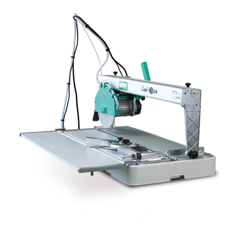
IMER
IMER COMBI 250 VA Guide
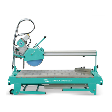
IMER
IMER C 350 i-Power Guide

IMER
IMER MASONRY 750 PLUS Guide
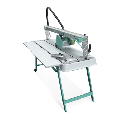
IMER
IMER COMBI 250/1000 VA Guide

IMER
IMER EASY 180 Guide

IMER
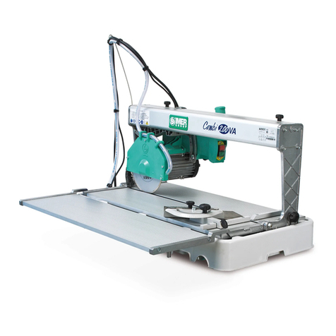
IMER COMBI 200 VA User manual
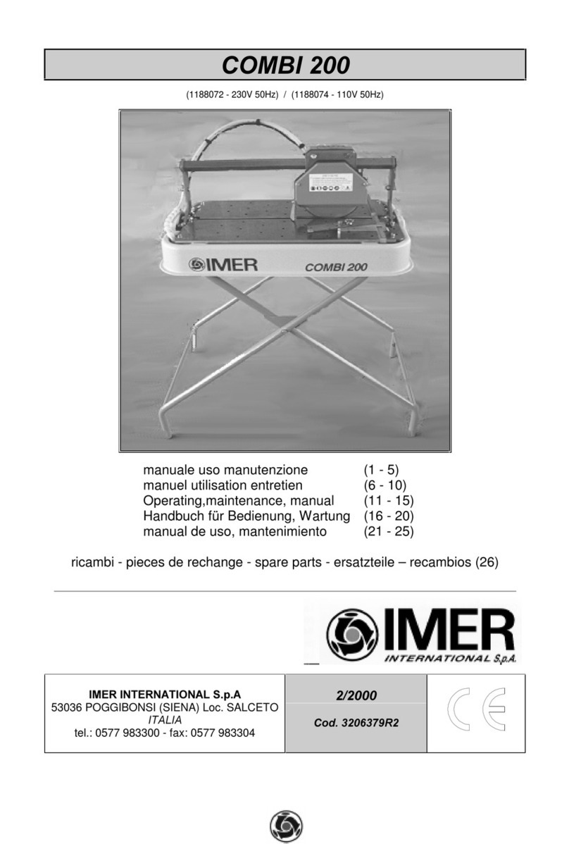
IMER
IMER Combi 200 Installation and operation manual
IMER
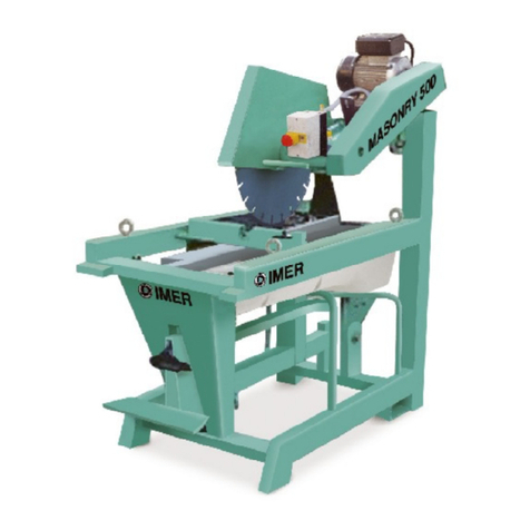
IMER MASONRY 500 Datasheet
IMER
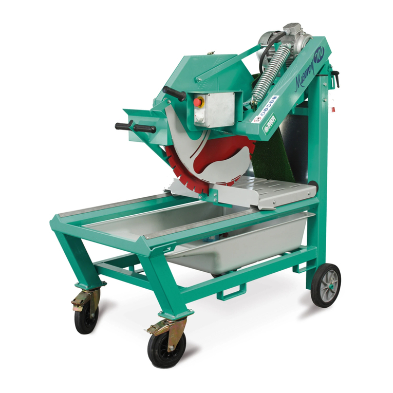
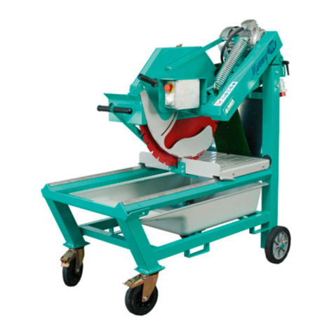
IMER MASONRY 700 Guide


