IMER 1188174 Guide

COMBI 250/1000 VA
SAWING MACHINE
1188174
OPERATING, MAINTENANCE, SPARE PARTS MANUAL
IMER WEST
3654, Enterprise Avenue
Hayward, CA 94545
Ph. 510.670.7970
Fax 510.783.4255
IMER EAST
221 Westhampton Place
Capitol Heights, MD 20743
Ph. 301.336.3700
Fax 301.336.6687
IMER U.S.A. Inc.
Toll Free: 800.275.5463
www.imerusa.com
2016/10 - R11
Cod. 3227118
COMBI 250/1500 VA
SAWING MACHINE
1188180

IMER U.S.A. Inc.
COMBI 250/1000 VA - COMBI 250/1500 VA
2
Dear Customer,
Congratulations on your choice of purchase: IMER saws are the result
of years of experience and are equipped with all the latest technical
innovations.
- WORKING IN SAFETY
To work in complete safety, read the following instructions care-
fully.
To work in complete safety, read the following instructions carefully be-
fore using the machine.
To work in complete safety, read the following instructions carefully be-
fore using the machine.
This OPERATION AND MAINTENANCE manual must be kept on site
by the person in charge, e.g. the SITE FOREMAN, and must always be
available for consultation.
The manual is to be considered integral part of the machine and must
be kept for future reference (EN 12100-2) until the machine is disposed
of. If the manual is damaged or lost, a replacement may be requested
from the manufacturer.
The manual contains important information regarding site preparation,
machine use, maintenance procedures, and requests for spare parts.
Nevertheless, the installer and the operator must both have adequate
experience and knowledge of the machine prior to use.
To guarantee complete safety of the operator, safe operation and long
life of equipment, follow the instructions in this manual carefully, and
observe all safety standards currently in force for the prevention of ac-
cidents at work (use of safety footwear and suitable clothing, helmets,
gloves, goggles etc.).
- Make sure that all signs are legible.
- It is strictly forbidden to carry out any form of modication to
the steel structure or working parts of the machine.
IMER INTERNATIONAL declines all responsibility for failure to com-
ply with laws and standards governing the use of this equipment, in
particular; improper use, defective power supply, lack of maintenance,
unauthorised modications, and partial or total failure to observe the
instructions contained in this manual.
IMER INTERNATIONAL reserves the right to modify features of the saw
and contents of this manual, without the obligation to update previous
machines and/or manuals.
1. TECHNICAL DATA
Technical data are stated in table 1 and electrical specications in table
2.
Table 1 - TECHNICAL DATA
Model Combi 250/1000 VA Combi 250/1500 VA
Max. blade diameter 10 inches 10 inches
Diamond Blade hole
diameter 5/8 inches 5/8 inches
Single phase 115V/60Hz
motor power 1.3 kW 1.3 kW
Max. blade rotation speed 3400 rpm 3400 rpm
Cutting table dimensions 1115x500 mm 1615 x500 mm
Length of 90° cuts
(thickness= 10mm)
Length of cuts from above
950 mm
1000 mm
1450 mm
1500 mm
Maximum cut depth with
single stroke
Maximum cut depth with
two stroke
66 mm
105 mm
66 mm
105 mm
Water pump ow rate 13 l/min 13 L/min
Water tank capacity 40 L 50 L
Machine dimensions 1420x636x619 mm 1920x636x619 mm
Packed machine
dimensions 1454x669x654 mm 1954x669x654 mm
Weight with packaging 65 kg 80 kg
Table 2
Feature Motor (115V/60Hz)
Power (kW) 1.3
Rated voltage (V) 115
Frequency (Hz) 60
Absorbed current 14.4
Number of poles 2
rpm 3400
Service type S6 40%
Insulation category F
Protection category IP55
Capacitor (µF) 110 (Ø 50x120)
2. DESIGN STANDARDS
Combi 250/1000 VA saws have been designed and manufactured ac-
cording to the following standards: UNI EN 12418:2001; EN 12100-
1/2:2005; EN 60204-1:2006.
3. SOUND PRESSURE LEVEL AND VIBRATIONS
Table 3 shows the sound pressure level measured loadless at the ope-
rator’s ear (LpA) and of the vibrations transmitted during operation.
Table 3
Model Type of motor LpA Aeq
Combi 250/1000 VA -
250/1500 VA Electric 86 dB 2.57 m/s2
4. GENERAL SAW DESCRIPTION
4.1 General description
The Combi 250/1000 VA (250/1500 VA)is a saw comprising the following
main sub-groups:
• cutter head (ref.A, g.1)
• runner guide and arms (ref.B, g.1)
• cutting tables and heads (ref.C, g.1)
• water collection tank (ref.D, g.1)
• frame (ref.E, g.1)
The cutting head is mounted on a reinforced aluminium prole and is
equipped with horizontal and vertical movement facilities. The alumi-
nium prole is hinged onto die-cast arms (ref.F, g.1) and the entire
unit can rotate through 45° (g.2) by means of the relative handwheels
(ref.G, g.2).
The machine is supported by a special metallic frame. There is a
shockproof plastic tank between the machine and the frame. The water
immersion pump is mounted below the cutting surfaces on a special bra-
cket and supplies a water distributor inside the blade guard for cooling
the cutting blade during operation.
The high resistance plastic handle (ref.H, g.2), is equipped with the
main ON-OFF switch on the operator side to facilitate saw activation
and shutdown.The raised position of the red OFF button on the handle is
designed to facilitate shutdown of the machine in the event of an emer-
gency. The motor capacitor is located in a protected position inside the
handle.
The saw is tted with a guard to guarantee optimal safety during opera-
tion and to protect the user during cutting cycles.
A valve is mounted above the blade guard to adjust the ow rate of water
delivered to the cutting blade. The version 250/1500 Va the movement
for the cutting head it is possible by the handle (rif Q, g 1)
4.2 Processable materials
This saw has been designed for cutting the following materials: ceramic
tiles, masonry and stone in general with maximum dimensions com-
patible with the length, cutting depth and dimensions of the surfaces
specied in table 1.
Maximum weight of processable materials: 25 kg.
4.3 Unsuitable material
Materials unsuitable for this machine are all those not specied in pa-
ragraph 4.2.
In any event, before using the saw with materials other than as specied
by the manufacturer for this saw model, contact IMER INTERNATIONAL
S.p.A.
- Use of this machine with workpieces outside the specied
dimensions is strictly prohibited and constitutes a hazard for the
operator.

IMER U.S.A. Inc.
COMBI 250/1000 VA - COMBI 250/1500 VA
3
5. OPERATION SAFETY
- Before using the saw, ensure that all protection devices are
tted.
- Never use the saw in environments subject to the risk of
explosions or re.
The saw is not tted with specic lighting and therefore the workplace
must be sufciently lit for this purpose (min. 300 lux).
The power lines must be laid to prevent any possible damage.
Ensure that the electrical connection is protected against the risk of wa-
ter penetration in connectors. Use exclusively connectors and couplings
equipped with water spray protection.
Never use inadequate or makeshift electrical lines or cables without
earthing; if in doubt consult a specialised technician.
Repairs to the electrical circuit must be performed exclusively by specia-
lised personnel. Disconnect the machine from the power supply before
performing maintenance or repairs.
6. GENERAL SAFETY WARNINGS
Note that this machine has been designed to ensure optimal performan-
ce and maximum safety: however the operator must also guarantee this
level of safety by paying special attention to the machine throughout all
work phases.
1. Ensure that an efcient earthing system is installed.
2. Work only with all protection devices tted correctly and in ef-
cient working order.
3. Remove rings, watches, bracelets or ties before using the ma-
chine; these elements constitute a serious hazard to the operator.
Also ensure that sleeves are tight around the wrists, hair is tied
back and robust footwear is used.
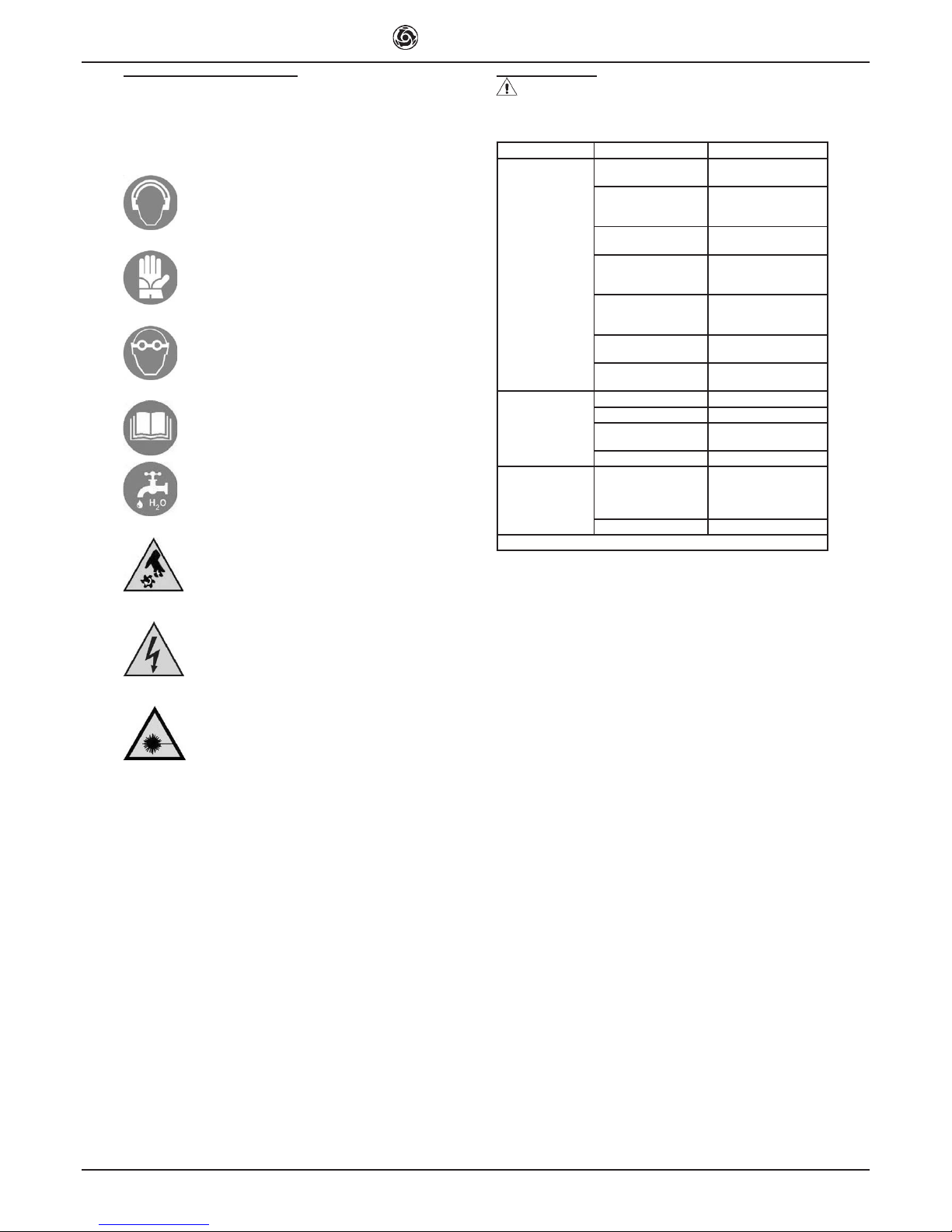
4. Always use personal protection devices such as safety goggles,
suitably sized gloves, ear muffs or plugs and hair caps when ne-
cessary.
5. Never cut workpieces that have dimensions or weight that are
not suited to machine i capacity as specied by the manufacturer
(see point 4.2)
6. Always keep your hands away from the work areas when the
machine is running. Before taking any action to remove a piece
from close to the disc, stop rotation by pressing the stop button.
7. Keep the machine clean: general cleaning (and the work surfa-
ces in particular) represents an important safety factor.
8. Always stop the machine and disconnect from the power supply
before cleaning or removing any protection device (for maintenan-
ce or disassembly purposes). If water jets are used for cleaning,
never point jets directly at the power supply unit or electric motor.
9. Use genuine diamond blades as recommended by the manufac-
turer to ensure optimal performance of the machine.
10. Use exclusively water-cooled continuous rim blades suited to
the material to be cut.
11. Never dry cut material or cut when cooling water levels are low.
12. Never use blades over the rotation speed specied by the ma-
nufacturer.
13. Do not use reduction rings to adapt the hole of the disc on the
ange. Only use discs with hole corresponding to the ange sup-
plied with the machine (1" or 7/8").
14. Never use diamond blades that are chipped or deformed.
15. The instructions in this manual are aimed at machine users
(operators, maintenance engineers).
7. SAFETY DEVICES
The Combi 250/1000 VA(250/1500 VA) has been constructed taking into
account current harmonised European safety standards.
According to machine directive 98/37/EEC all safety devices have been
installed with the aim of safeguarding the operator.
7.1 Guards and safety devices
The machine is equipped with xed guards, secured by means of screws
and protections that prevent access to moving or dangerous parts.
All xed guards, covers, shields xed by means of screws have been
envisaged to protect the operator (maintenance engineers, technicians
and others) from possible accidents cause by electrical discharge or
moving mechanical parts.
Therefore use of the machine with guards removed or modied in any
way is strictly prohibited.
- Before performing maintenance or repairs to the machine,
turn it off via the main switch and disconnect from the power sup-
ply to prevent inadvertent start-up and isolate all machine electri-
cal circuits.
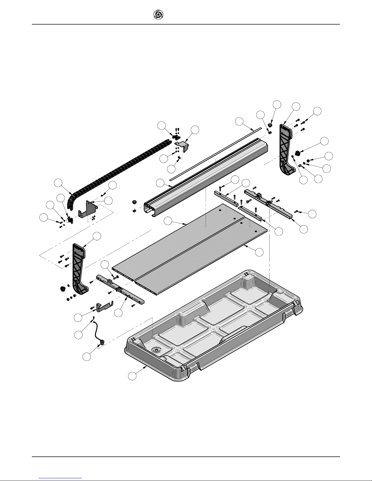
8. MACHINE INSTALLATION
8.1 Set up
Remove the machine packing.
The machine can already be used, leaving the legs folded, resting its
frame on a sufciently even surface at least as big as the tank.
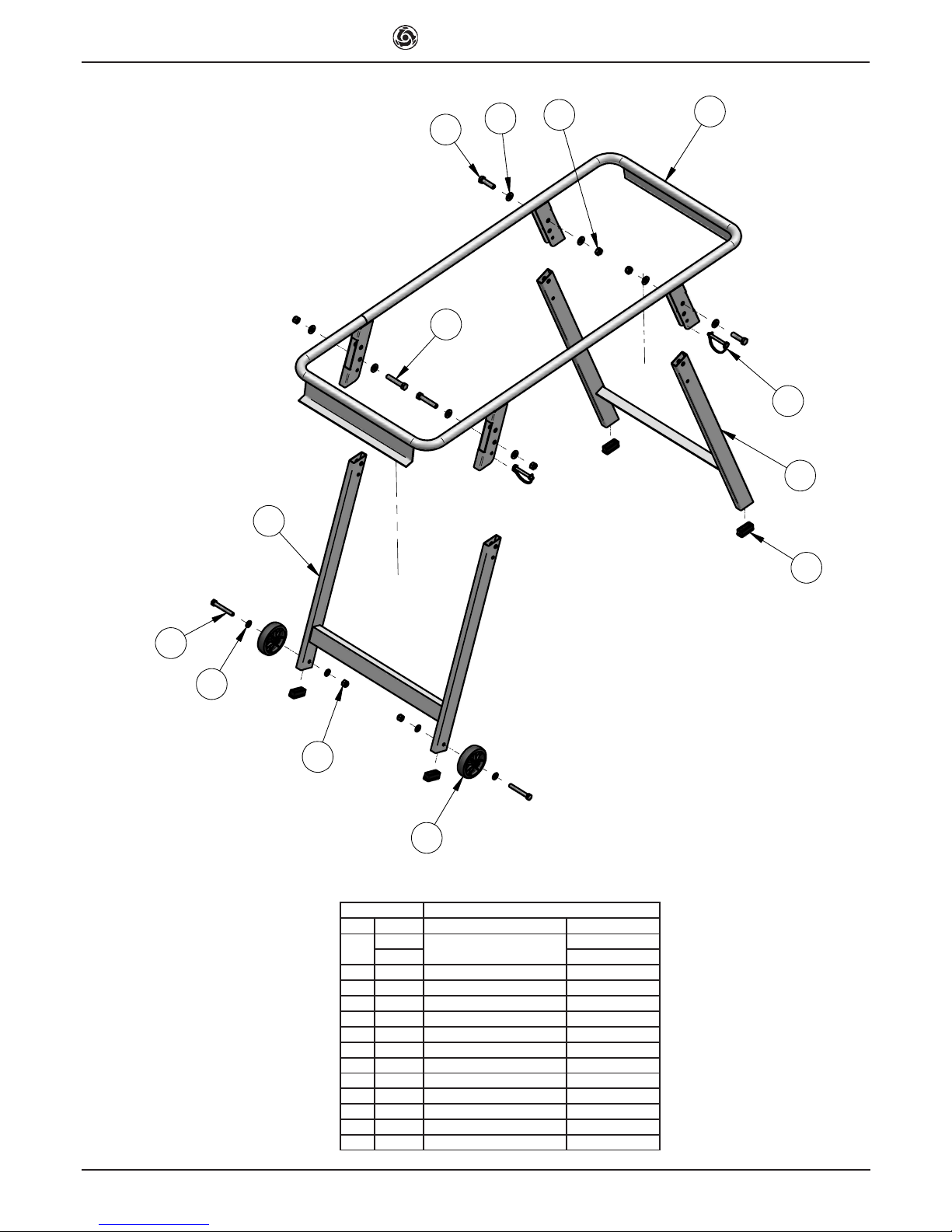
Frame assembly:
1. remove the machine and tank from the folded frame.
2. remove the safety pins from the frame and open the legs.
3. put the safety pins back in the holes provided locking the legs in the
open position.
4. reposition the machine and tank on the frame.
- Make sure that the frame is positioned on a at and even sur-
face, capable of bearing the weight of the machine. The maximum
permissible gradient in all directions is 6°.
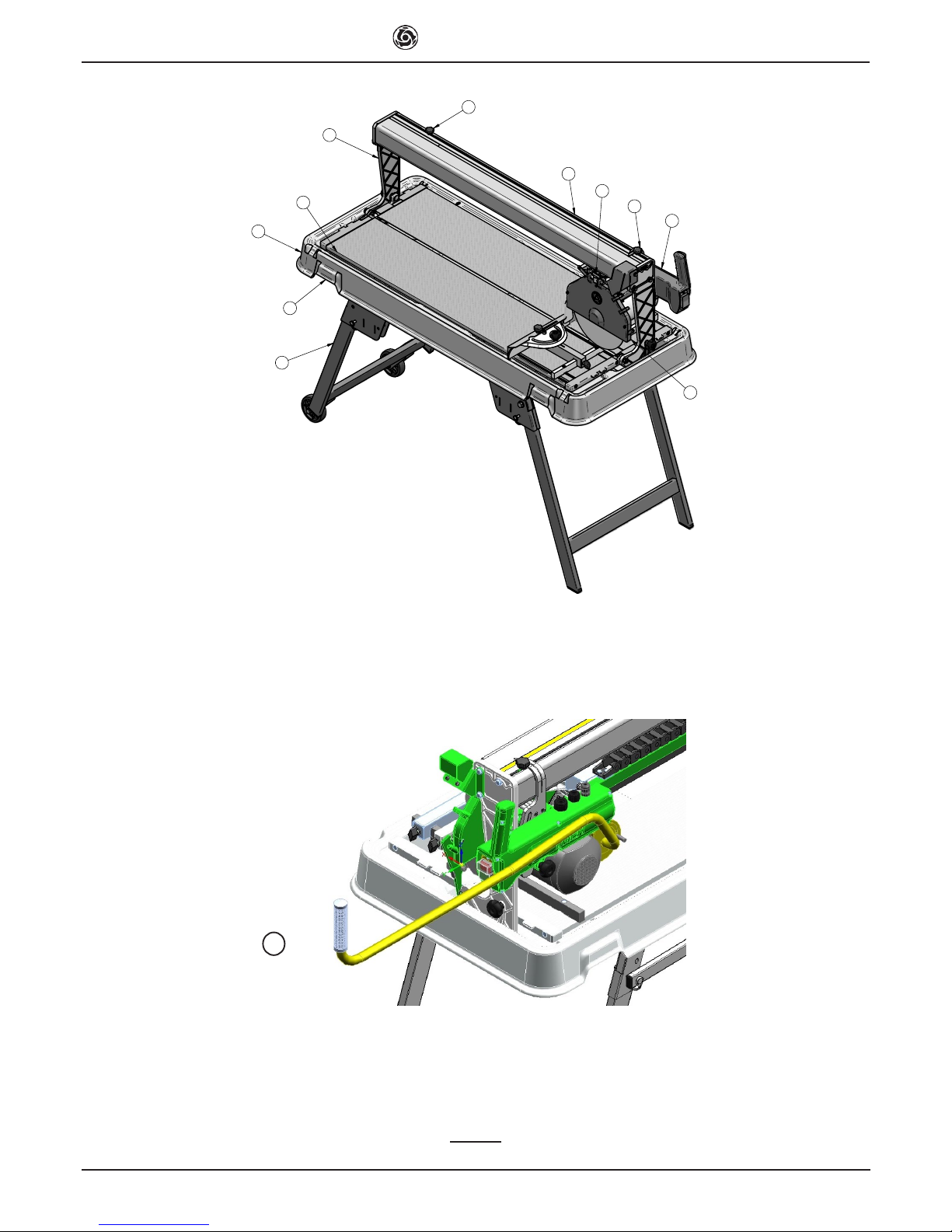
8.2 Handling
The Combi 250/1000 VA sawing machine weighs 57 Kg(250/1500 VA
80 kg) and can be moved using the side handles on the tank (ref.I,
g.1). For short distances use the wheels tted on the frame. For longer
distances, before moving the machine, close the frame reversing the
sequence of the operations described in point 8.1.
Every time the machine is moved, make sure the head is locked tighte-
ning the knobs (ref.L, g.1).
- Always empty the tank before moving the machine.
- Always disconnect the power plug before moving the ma-
chine.
8.3 Additional table assembly (optional kit code 1188176)
The additional table can be installed to the left or right of the machine, or
on both sides at the same time.
First t the cross member (ref.5, g.6) to the bolts on the frame (ref.A,
g.6) and secure it with the nut and washer (ref.6-7, g.6). Secure the
other end of the cross member with the locking pin (ref.8, g.6) on the
front legs.
Fit the strut (ref.1, g.6) to the cross member, making sure that it locates
into the grooves, which hold it perfectly vertical.
Now install the additional table; it is supplied with the side mounts alre-
ady assembled. Fit the mounts into the provided cavities in the side
panels of the machine, making sure they are fully inserted. Now lower
the additional table until it is properly supported. Level the additional
table with that of the machine itself; to do this, move the strut to the left
or right along the cross member (g.6).
- The use of additional tables without props can cause damage
to them.
9. ELECTRICAL CONNECTION
- Ensure that voltage corresponds to machine dataplate spe-
cications.
The power supply line must be equipped with current overload protec-
tion (e.g. thermal cutout) and protection against indirect contact (e.g.
residual current circuit breaker).
Connect the machine to an efcient earthing system.
The size of the power cable wires must be based on operating current
and length of the power line to prevent excessive voltage drops (table
4).
Table 4
Model Type of motor Cable (mm²)
1.5 2.5 4.0
Combi 250/1000 VA
-250/1500 VA
115 V
14.4 A 0 ÷ 12 13 ÷ 20 21 ÷ 32
Cable
length (m)
Connect the saw plug to the mains and tighten the mechanical retainer
ring with IP67 protection rating.
The saw is now ready for operation.

IMER U.S.A. Inc.
COMBI 250/1000 VA - COMBI 250/1500 VA
4
10. MACHINE USE
10.1 Operation
The correct side for the operator is shown in g.4 ref.X.
Fill the water tank to the maximum level (approx. 40 litres).
Connect the machine to the power mains and start as described in pa-
ragraph 10.
Open the valve (ref.N, g.1) and ensure sufcient ow of cooling water
to the diamond blade.
10.2 Cutting
Rest the material to be cut on the cutting table against the stopper. De-
ne the required inclination using the goniometer. To adjust the cutting
head height, loosen the handwheel (ref.O, g.3), position the head at
the required height, then fully tighten the handwheel. Make sure that
handwheels for sloped cutting (ref.G, g.2) are rmly tightened. Start the
sawing machine as described in paragraph 10. To proceed with cutting,
press the piece to be cut on the table with your hand and move the cutter
head gripping the handle and drawing it towards you. If the feed speed
is too fast in relation to the thickness and hardness of the material the
blade might stop turning. In this case, release the disk as quickly as
possible moving the cutter head away from you until the disk recovers
its nominal rotation speed. Resume cutting, adjusting the feed speed
according to the characteristics of the material.
10.3 Angled cuts
Loosen the handwheels (ref.G, g.2), set the cutting head at the requi-
red angle, retighten the handwheels, and proceed as described in the
point above.
- Ensure that the tank is kept full during all work phases and in
the event of prolonged work intervals replace water regularly and
remove all processing residue.
10.4 Laser pointer
The machine is tted with a laser pointer that reproduces the cutting line
on the piece being machined. The track of light indicates the trajectory
of the diamond disk during the feed motion. Making the required cutting
prole coincide with the laser prole, it is possible to ensure the highest
accuracy of the operation.
Cuts at right angle with one side of the piece being machined do not re-
quire tracing beforehand: in fact it will sufce to make sure that the side
of reference is in contact with the stopper on the resting surface. Likewi-
se, using the goniometer, cutting at predened inclinations is possible.
The laser light will indicate the actual position of the cut.
The laser pointer is activated when the machine is connected to the
electric mains.
The pointer is aligned with the disk and must not be moved from its
initial position.
- The pointer used emits a low power laser light, but it is in any
case advisable to avoid looking directly at the emitter itself.
11. MAINTENANCE
11.1 Premise
Routine maintenance operations can also be performed by non-speciali-
sed personnel provided that all safety standards specied in the relative
sections of this manual are observed at all times.
11.2 Machine cleaning
The machine should be cleaned exclusively when it is stationary.
- All power switches must be set to “0” and plugs must be
disconnected from the mains.
1. Never use compressed air; this could cause inltration of dust or re-
sidue in enclosed parts.
2. Ensure that the cooling water nozzles are not obstructed.
3. Above all the cooling water in the tank must be changed every day.
4. Do not use detergents or lubricants.
11.3 Cleaning the tank
Clean the tank in the event of build-up of sediment on the base, or at le-
ast once a day. Failure to clean the tank could impair operation of the im-
mersion pump used for circulation of the diamond blade cooling water.
To clean the tank, disassemble from the machine, lock the head, hold it
by the arms and rinse with a direct water jet (this is to avoid direct con-
tact of the water with electrical parts), the proceed with manual cleaning
using cloths or brushes.
Take care not to damage cables when replacing the machine on the tank
Take care not to damage the pump when placing the machine on the
surface
11.4 Cleaning the cooling water supply circuit
At regular intervals (or when the ow rate of the blade cooling water is
reduced) clean the cooling water supply circuit. To do this, disassemble
the delivery nozzle (ref.P, g.1) located inside the blade guard and clean
in water.
Periodically clean the cooling water delivery line between the pump and
valve and blade guard using water.
11.5 Blade replacement
The diamond blade is made of material that may be damaged when
subject to high temperatures, and therefore must be cooled during the
work phases.
To replace the blade, proceed as follows:
1. Block axial movement of the cutting head by means of the handwhe-
els (ref.L, g.1).
2. Disassemble the front guard (ref.P, g.1).
3. Loosen the locknut by rotating clockwise (left thread), using a 19 mm
wrench.
4. Move the cutting head forward slightly and incline to remove the blade
from its seat.
5. Ensure that there are no foreign objects between the xing ange and
diamond blade. During disassembly, avoid use of tools that could dent
or deform the ange.
6. Insert the new blade proceeding in reverse order of the operation
described at point 4. Take special care to ensure correct direction of
rotation of the diamond blade.
7. Tighten the blade locknut fully down by rotating anticlockwise (left
thread), to a torque of 40 Nm.
- Always disconnect the power plug before changing the disk.
11.6 Repairs
Repairs to the electrical installation must be performed exclusively by
specialised personnel. Use exclusively original IMER spare parts; modi-
cations to parts are strictly prohibited. The special design of the Combi
250/1000 VA ensures that no other maintenance other than as specied
above is required.
Ensure that the contacts of the power plug and plug-switch assembly
are efcient. If oxidation is detected, clean immediately
- In the event of activation of the RCCB, check the machine
and arrange for repairs if necessary exclusively by specialised
personnel.
11.7 Waste disposal
As regards disposal of processing waste observe all current legislation
in the country of use.

IMER U.S.A. Inc.
COMBI 250/1000 VA - COMBI 250/1500 VA
5
12. Residual risks and safety signs
Although the sawing machine has been manufactured fully in complian-
ce with current regulations, residual risks exist that cannot be eliminated
and involve the use of appropriate individual protection devices. Ade-
quate warning signs tted on the machine point out both the risks and
the behaviour to be followed.
NOISE RISK
Ear protection must be worn
RISK OF INJURY TO THE HANDS
Safety gloves must be worn
RISK OF INJURY TO THE EYES
Eye protection must be worn
ABNORMAL USE RISK
Reading the manual before use is compulsory
Cutting with water is compulsory
DANGER OF CUTTING
DANGER OF ELECTROCUTION
DANGER OF LASER BEAM
Please be reminded that checking the use of IPDs is delegated to the
employer.
14. Troubleshooting
- CAUTION!!! All maintenance operations must be performed
exclusively with the machine switched off, with the selector set to
“0” and the power plug disconnected from the mains.
Trouble Causes Remedies
The motor does not
start when the start
switch is pressed
Current does not reach
the supply line
Check the line *
The socket and plug
are not connected
properly
Restore correct
connection
The differential switch
is off
Turn the differential
switch on
The power cable from
the plug to the panel
is cut off
Change the cable *
An electric wire inside
the motor terminal strip
is cut off
Restore the connection *
An electric wire inside
the panel is cut off
Change the switch *
The start switch is
faulty
Change the switch *
Cooling water fails
to reach the blade
Low water level in tank Restore the water level
Pump lter clogged Clean the pump lter
Current fails to reach
the pump
Check the pump
electrical supply *
Pump failure Change the pump *
The blade does
not cut
Blade tted in the
opposite direction to
that of rotation
Remove the blade
and reposition it in the
direction shown on the
blade label
Worn blade Change the blade
* Operation to be carried out by an electrician

IMER U.S.A. Inc.
COMBI 250/1000 VA - COMBI 250/1500 VA
6
A
B
C
E
D
F
I
L
L
N
P
FIG. 1
Q

IMER U.S.A. Inc.
COMBI 250/1000 VA - COMBI 250/1500 VA
7
FIG. 2
G
H
M
FIG. 3
O
FIG. 4
X

IMER U.S.A. Inc.
COMBI 250/1000 VA - COMBI 250/1500 VA
8
34
18
27
23
16
17
26
19
11
12 13
14
5
4
9
10
20
21
7
6
24
25
2
3
28
8
29
30
32
1
22
15
31 33
35

IMER U.S.A. Inc.
COMBI 250/1000 VA - COMBI 250/1500 VA
9
TAV. 1 - MACHINE STRUCTURE
REF. CODE DESCRIPTION NOTES
13226951 TANK CM250/1000 VA
3234825 CM 250/1500 VA
23227485 R.H. SURFACE CM250/1000 VA
3234845 CM 250/1500 VA
33227486 L.H. SURFACE CM250/1000 VA
3234846 CM 250/1500 VA
4 3226070 REAR SIDE
5 3226069 FRONT SIDE
6 3226359 REAR ARM
7 3226357 FRONT ARM
83227459 SLIDEWAY CM250/1000 VA
3234828 CM 250/1500 VA
9 3226073 RIGHT FENCE
10 3226074 LEFT FENCE
11 3209797 BOLT TE 5739 M5X16
12 3210071 T-NUT
13 3226709 BOLT TEFR 6X35
14 3210576 WASHER D.8,4X17X1,5
15 3225750 BOLT TEFR 6X10
16 2224529 WASHER D.5X10
17 2235429 CAP
18 2222545 BOLT TCEI 5931 M6X30
19 3204865 KNOB M6
20 3226087 WASHER D.10,5X17X1,5
21 3226088 BUSHING
22 2223927 NUT 7474 M5
23 2223920 NUT 7474 M10
24 3226747 BOLT TTDE 5732 8X40
25 3226795 MILLIMETRED STRIP CM250/1000 VA
3232981 CM 250/1500 VA
26 2284866 KNOB M8
27 2222584 BOLT TSPEI 5933 M6X25
28 3226944 BRACKET
29 3226946 CABLE HOLDER CHAIN CM250/1000 VA
3234831 CM 250/1500 VA
30 3226947 MALE TERMINAL
31 3226948 FEMALE TERMINAL
32 3226949 BRACKET
33 3226950 BRACKET
34 2222449 BOLT TC 6954 3.5X19
35 3227488 CABLE DUCT D.4

IMER U.S.A. Inc.
COMBI 250/1000 VA - COMBI 250/1500 VA
10
12
10
11
4
5
6
7
8
9
2
3
1
13
TAV. 2 - COMPLETE FRAME
REF. CODE DESCRIPTION NOTES
13229892 FRAME CM250/1000VA
3234829 CM 250/1500 VA
2 3229852 FRONT LEGS
3 3229853 REAR LEGS
4 2224380 WASHER 6592 D.12X25
5 3229916 BOLT TE 5739 M10X60
6 3205257 WHEEL
7 3223143 PIN 8X70 Z
8 2222050 BOLT TE 5739 M12X50
9 3226976 CAP
10 2223921 NUT 7474 M12
11 2224340 WASHER 6592 D.10X21
12 2223920 NUT 7474 M10
13 3224959 BOLT 5739 M12X65

IMER U.S.A. Inc.
COMBI 250/1000 VA - COMBI 250/1500 VA
11
3226358 TAV. 3 - COMPLETE GONIOMETER
REF. CODE DESCRIPTION NOTES
1 3230617 GONIOMETER SUPPORT
2 3230616 GONIOMETER
3 3226360 SLIDING ROD
4 2224140 WASHER 6593 D.8X18
5 3207939 HANDWHEEL M8X30
6 3211381 HANDWHEEL M8X30
7 3223279 HANDWHEEL M6X20
8 3230638 SPACER
9 2222511 BOLT TCEI 5931 M8X25
10 3231271 BAR
TAV 3-BIS - HANDLE GROUP
RIF. COD. DESCRIPTION NOTE
1 2288885 HANDLE
2 3234889 HANDLE
3 3234892 CONNECTING PLATE
4 3234891 CONNECTING PLATE
9
4
5
6
7
1
2
3
8
10
6

IMER U.S.A. Inc.
COMBI 250/1000 VA - COMBI 250/1500 VA
12
TAV. 4 - BLADE PROTECTION MOTOR ASSEMBLY
REF. CODE DESCRIPTION NOTES
1 3230037 MOTOR
2 3230255 ENGINE SUPPORT
3 3210087 SPRING
4 3211935 BLADE GUARD
5 3210043 SPACER BRACKET
6 3210238 INNER FLANGE
7 1193782 BLADE
8 3210046 OUTER FLANGE
9 3211933 BLADE GUARD
10 2224535 WASHER
11 2222587 BOLT TSPEI 5933 M8X20
12 3204399 BOLT TCEI 5931 M5X25
13 3207884 COCK
14 3209060 BOLT TE 8.8 5737 M6X35
15 2222001 BOLT TE 8.8 5737 M4X20
16 2223352 NUT 5588 D.5
17 2223920 NUT 7474 M10
18 2223926 NUT 7473 M4
19 3210050 SPRAY SHIELD
20 3210053 NUT 5588 M12 Z SX
21 2222540 BOLT TCEI 5931 M6X20
22 2224380 WASHER 6592 D.12X25
23 2223280 NUT 5588 M6
24 2223924 NUT 7473 M6
25 3230251 BUSHING GFM-1012-6
26 3230250 GOUPILLE
27 3230644 FAN COVER
7
15
21
23
16
17
18
22
10
11
12
13
14
2
5
6
8
19
20
9
4
1
24
3
25
26
27

IMER U.S.A. Inc.
COMBI 250/1000 VA - COMBI 250/1500 VA
13
TAV. 5 - ELECTRIC PANEL
REF. CODE DESCRIPTION NOTES
1 3227467 JUNCTION BOX
2 3210114 GASKET
3 3210231 COVER
4 3210232 CAPACITOR
5 3210233 SWITCH
6 3209340 LEAKAGE PROTECTION
7 3225596 GASKET
8 3233422 WATER PUMP
9 3226095 CABLE GLAND LOCKING RING PG 16
10 3226101 CABLE GLAND GROMMET PG 16
11 3226098 CABLE GLAND LOCKING RING PG 11
12 3226100 CABLE GLAND GROMMET PG 11
13 3210116 BOLT TCTC 4,2X16
14 2222540 BOLT TCEI 5931 6X20
15 3210096 BOLT TTCQ 5732-65 M8X60
16 2284866 HANDWHEEL 180-40-M8
17 3224630 PLUG + ELECTRIC CABLE
18 3227508 CABLE CLAMP PG 9
19 3227487 CABLE GLAND NUT PG 9
20 3227481 SUPPORT
21 3227483 ADJUSTMENT BLOCK
22 3227489 CABLE GLAND NUT M20x1.5
23 3228250 LASER
24 3207155 BOLT TC PH 7687 M4X10
25 3227482 COVER
26 3228251 POWER SUPPLY
27 2222424 BOLT TC PH 6954 4.2X9.5
8
14
5
1
3
15
2
13
4
7
911
12
10
17
19
18
27
24
21
22
23
26
25
20
16
6

IMER U.S.A. Inc.
COMBI 250/1000 VA - COMBI 250/1500 VA
14
WIRING DIAGRAM
REF. DESCRIPTION
S1 CONTROL SWITCH
C1 CAPACITOR
PE EARTHING CABLE
N NEUTRAL LINE CABLE
L1 PHASE LINE CONDUCTOR
M1 BLADE MOTOR
M2 PUMP MOTOR
ID CURRENT CIRCUIT
BREAKER
TR1 POWER SUPPLY
D1 LASER EMITTER
L1 NPE
M1
M2
11
S1
U<
I d
TR1
D1
C1
LASER

IMER U.S.A. Inc.
COMBI 250/1000 VA - COMBI 250/1500 VA
15
TAV. 6 - CARRIAGE
REF. CODE DESCRIPTION NOTES
1 3210031 CARRIAGE
2 3210032 CAM
3 3207393 SPACER BRACKET
4 3204945 BEARING 608 2RS1
5 3207397 WHEEL ASSEMBLY
6 3210627 RING
7 3210036 BOLT TCEI 5931 M5X16
8 3210622 SPACER BRACKET
9 2222114 BOLT TE 5737 M8X90
10 2223923 NUT 7473 M8
11 3210028 CARRIAGE BLOCK
12 3210105 BOLT TSP PH M5X12
13 3210029 BLADE GUARD
14 2222000 BOLT TE 5739 M5X16
14
9
10
4
3
5
11
13
1
2
7
12
8
6

IMER U.S.A. Inc.
COMBI 250/1000 VA - COMBI 250/1500 VA
16
4
3
2
5
1
8
7
6
A
FIG. 6
Table Complete 1188179
TAV. 7 - SIDE ROLLER
REF. CODE DESCRIPTION NOTES
1 3229847 SUPPORT
2 3226145 SUPPORT
3 3226146 SUPPORT
43226952 SIDE ROLLER CM250/1000 VA
3234832 CM250/1500 VA
53229851 SUPPORT CM250/1000 VA
3234833 CM250/1500 VA
6 2224380 WASHER 6592 D.12X25 Z
7 2223921 NUT 7474 M12
8 3223143 PIN 8X70 Z

IMER U.S.A. Inc.
COMBI 250/1000 VA - COMBI 250/1500 VA
17
COD.1188159 DESCRIPTION
RIF. COD. NOTE
1 3226949 PUMP BRACKET
2 3234969 ROD
3 3234974 SHEET
4 2222013 M 6 X 40Z UNI-5737
5 2223924 SELF-LOCKING
NUT M6
6 3235155 HANDWHEEL M6X40
7 2223260 NUT 5587 M6
8 3234968 SEAL 20X15

IMER U.S.A. Inc.
COMBI 250/1000 VA - COMBI 250/1500 VA
18
ONE YEAR WARRANTY
We warrant to the original purchaser that the IMER equipment described herein (the
"equipment") shall be free from defects in material and workmanship under normal use
and service for which it was intended for a period of one (1) year from the date of purchase
by the original purchaser.
Our obbligation under this warranty is expressely limited to replacing or repairing, free of
charge, F.O.B. our designated service facility, such part or parts of the equipment as our
inspection shall disclose to be defective. Parts such as engines, motors, pumps, valves,
electric motors, etc. furnished by us but not manifactured by us will carry only the warranty
of the manifacturer. Transportation charges or duties shall be borne by the purchaser. This
shall be the limit of our liability with respect to the quality of the equipment.
This warranty shall not apply to any equipment, or parts thereof, which has been damaged
by reason of accident, negligence, unreasonable use, faulty repairs, or which has not been
mantained and operated in accordance with our printed instructions for our equipment.
Further, this warranty is void if the equipment, or any of its components, is altered or modi-
ed in any way.
THIS WARRANTY IS EXPRESSLY IN LIEU OF ALL OTHER WARRANTIES, EXPRES-
SED OR IMPLIED, INCLUDING ANY IMPLIED WARRANTY OF MERCHANTABILITY OF
FITNESS FOR A PARTICULAR PURPOSE.
We make no other warranty, representation or guarantee, nor is anyone authorized to
make one on our behalf. We shall not be liable for any consequential damage of any kind,
including loss or damage resulting, directly or indirectly, from the use or loss of use of the
machine. Without limiting the generality of the foregoing, this exclusion from liability em-
braces the purchase's expenses for downtime, damages for which the purchaser may be
liable to other persons, damages to property, and injury or death of any persons.
This warranty shall not be deemed to cover maintenance parts, including but not limited
to blades, belts, hoses, hydraulic oil or lters, for which we shall have no responsability or
liability whatsoever.
IMER U.S.A. Inc.
221 Westhampton Place
Capitol Heights, MD 20743
Ph. 301.336.3700
Fax 301.336.6687
Toll Free: 800.275.5463
www.imerusa.com
This manual suits for next models
3
Table of contents
Other IMER Saw manuals