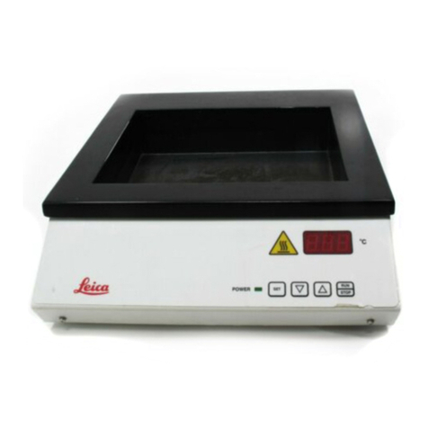
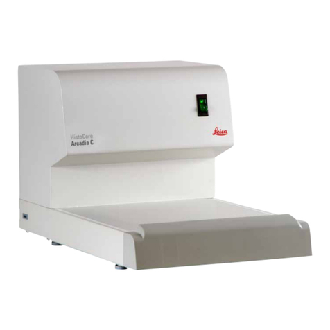
Leica HistoCore Arcadia H User manual

HistoCore Arcadia H
Paraffin Embedding Station
Instructions for Use
English
Order No.: 14 0393 81101 - Revision K
Always keep this Instructions for Use with the instrument.
Read carefully before working with the instrument.
Version 1.8, Revision K - 10.2018


3
HistoCore Arcadia H
The information, numerical data, notes and value judgments contained in this Instructions for Use
represent the current state of scientific knowledge and state-of-the-art technology as we understand
it following thorough investigation in this field.
We are under no obligation to update the present Instructions for Use periodically and on an ongoing
basis according to the latest technical developments, nor to provide our customers with additional
copies, updates etc. of this Instructions for Use.
To the extent permitted in accordance with the national legal system as applicable in each individual
case, we shall not be held liable for erroneous statements, drawings, technical illustrations etc.
contained in this Instructions for Use. In particular, no liability whatsoever is accepted for any financial
loss or consequential damage caused by or related to compliance with statements or other information
in this Instructions for Use.
Statements, drawings, illustrations and other information regarding the contents or technical details of
the present Instructions for Use are not to be considered warranted characteristics of our products.
These are determined only by the contract provisions agreed between ourselves and our customers.
Leica Biosystems reserves the right to change technical specifications as well as manufacturing
processes without prior notice. Only in this way is it possible to continuously improve the technology
and manufacturing techniques used in our products.
This document is protected under copyright laws. All copyrights to this documentation are held by
Leica Biosystems Nussloch GmbH.
Any reproduction of text and illustrations (or of any parts thereof) by means of print, photocopy,
microfiche, web cam or other methods – including any electronic systems and media – requires express
prior permission in writing by Leica Biosystems Nussloch GmbH.
For the instrument serial number and year of manufacture, please refer to the nameplate on the back of
the instrument.
Note
Leica Biosystems Nussloch GmbH
Heidelberger Str. 17 - 19
D-69226 Nussloch
Germany
Tel.: +49 - (0) 6224 - 143 0
Fax: +49 - (0) 6224 - 143 268
Web: www.LeicaBiosystems.com
Assembly contracted to Leica Microsystems Ltd. Shanghai

4Version 1.8, Revision K
Table of contents
1. Important Information ................................................................................................................................ 6
1.1 Naming conventions ....................................................................................................................................... 6
1.2 Symbols in the text and their meanings....................................................................................................... 6
1.3 Instrument type.............................................................................................................................................. 10
1.4 Intended use of instrument.......................................................................................................................... 10
1.5 Qualification of personnel............................................................................................................................ 10
2. Safety .......................................................................................................................................................... 11
2.1 Safety Notes................................................................................................................................................... 11
2.2 Warnings......................................................................................................................................................... 12
2.3 Integrated safety devices............................................................................................................................. 13
3. Instrument Components and Specifications........................................................................................ 14
3.1 Overview – Instrument components .......................................................................................................... 14
3.2 Main features of the instrument.................................................................................................................. 15
3.3 Technical Data............................................................................................................................................... 16
4. Setting up the instrument ........................................................................................................................ 18
4.1 Site requirement ............................................................................................................................................ 18
4.2 Standard delivery – packing list.................................................................................................................. 18
4.3 Unpacking and installation........................................................................................................................... 19
4.4 Necessary assembly work........................................................................................................................... 20
4.5 Electrical connection.................................................................................................................................... 22
4.6 Moving the instrument.................................................................................................................................. 22
5. Operation.................................................................................................................................................... 23
5.1 Instrument parts/functions........................................................................................................................... 23
5.2 Switching the instrument on........................................................................................................................ 28
5.3 Control panel functions................................................................................................................................. 29
5.4 Operation modes............................................................................................................................................ 33
5.5 Instrument heater.......................................................................................................................................... 34
6. Maintenance and Cleaning..................................................................................................................... 35
6.1 Cleaning the instrument................................................................................................................................ 35
6.2 Maintenance instructions............................................................................................................................ 36
7. Troubleshooting ........................................................................................................................................ 37
7.1 Error message................................................................................................................................................ 37
7.2 Possible faults................................................................................................................................................ 40
7.3 Changing a fuse ............................................................................................................................................. 41
8. Optional Accessories............................................................................................................................... 43
8.1 Magnifier......................................................................................................................................................... 43
8.2 Foot switch...................................................................................................................................................... 43
8.3 Pre-filter cup................................................................................................................................................... 45
8.4 Basket handle................................................................................................................................................. 45
8.5 Ordering information..................................................................................................................................... 45

5
HistoCore Arcadia H
Table of contents
9. Warranty and Service .............................................................................................................................. 47
10. Decontamination Confirmation.............................................................................................................. 48

6Version 1.8, Revision K
Important Information
1
1. Important Information
1.1 Naming conventions
Note
The full name of the device is HistoCore Arcadia H Paraffin Embedding Station. The device is called
HistoCore Arcadia H to ensure that the Instructions for Use are well legible.
1.2 Symbols in the text and their meanings
Symbol: Title of the symbol: Warning
Description: Warnings appear in a white box and are marked by a
warning triangle.
Symbol: Title of the symbol: Note
Description: Notes, i. e. important user information, appear in a
white box and are marked by an information symbol.
Symbol: Title of the symbol: Item number
→"Fig. 7-1"Description: Item numbers for numbering illustrations. Numbers in
red refer to item numbers in illustrations.
Symbol: Title of the symbol: Function key
Save Description: Function keys, that have to be pressed on the display
screen displayed as bold, gray text.
Symbol: Title of the symbol: Warning, hot surface
Description: Instrument surfaces which become hot during
operation are marked with this symbol. Avoid direct
contact to prevent risk of burning.
Symbol: Title of the symbol: Flammable
Description: Flammable reagents, solvents and cleaning agents
are labeled with this symbol.
Symbol: Title of the symbol: Caution
Description: Indicates the need for the user to consult the
Instructions for Use for important cautionary
information such as warnings and precautions that
cannot, for a variety of reasons, be presented on the
medical device itself.
Symbol: Title of the symbol: ON (Power)
Description: The power supply is connected upon pushing the
power switch.

7
HistoCore Arcadia H
Important Information 1
Symbol: Title of the symbol: OFF (Power)
Description: The power supply is disconnected upon pushing the
power switch.
Symbol: Title of the symbol: Consult Instructions for Use
Description: Indicates the need for the user to consult the
Instructions for Use.
Symbol: Title of the symbol: Manufacturer
Description: Indicates the manufacturer of the medical product.
Symbol: Title of the symbol: Manufacturing date
Description: Indicates the date when the medical device was
manufactured.
Symbol: Title of the symbol: Alternating current
Symbol: Title of the symbol: PE terminal
Symbol: Title of the symbol: Article number
Description: Indicates the manufacturer's catalog number so that
the medical device can be identified.
Symbol: Title of the symbol: Serial number
Description: Indicates the manufacturer's serial number so that a
specific medical device can be identified.
Symbol: Title of the symbol: China ROHS
Description: Environmental protection symbol of the China RoHS
directive. The number in the symbol indicates the
"Environment-friendly Use Period" of the product in
years. The symbol is used if a substance restricted
in China is used in excess of the maximum permitted
limit.
Symbol: Title of the symbol: WEEE Symbol
Description: The WEEE symbol, indicating separate collection
for WEEE – Waste of electrical and electronic
equipment, consists of the crossed-out wheeled bin
(§ 7 ElektroG).
Symbol: Title of the symbol: CE Compliance
Description: The CE marking is the manufacturer's declaration
that the medical product meets the requirements of
the applicable EC directives.

8Version 1.8, Revision K
Important Information
1
Symbol: Title of the symbol: CSA Statement (Canada/USA)
Description: This product fulfills the requirements of the CAN/
CSA-C22.2 No. 61010.
Symbol: Title of the symbol: Fragile, handle with care
Description: Indicates a medical device that can be broken or
damaged if not handled carefully.
Symbol: Title of the symbol: Store dry
Description: Indicates a medical device that needs to be
protected from moisture.
Symbol: Title of the symbol: This way up
Description: Indicates correct upright position of the transport
package.
Symbol: Title of the symbol: Stack limit
Description: It allows maximum 2 stacks layers.
Symbol: Title of the symbol: Temperature limit for transport
Description: Indicates the temperature limits for transport to
which the medical device can be safely exposed.
Symbol: Title of the symbol: Temperature limit for storage
Description: Indicates the temperature limits for storage to which
the medical device can be safely exposed.

9
HistoCore Arcadia H
Important Information 1
Symbol: Title of the symbol: Humidity limitation for transport and storage
Description: Indicates the range of humidity for transport and
storage to which the medical device can be safely
exposed.
Symbol: Title of the symbol: Shockdot Impact Indicator
Description: In the Shockwatch system, a shock dot shows
shocks or impacts that are above a specified
intensity through red coloration. Exceeding a defined
acceleration (g value) causes the indicator tube to
change color.
Symbol: Title of the symbol: Tilt indicator
Description: Indicator to monitor whether the shipment has been
transported and stored in upright position according
to your requirements. With a pitch of 60° or more,
the blue quartz sand flows into the arrow-shaped
indicator window and sticks there permanently.
Improper handling of the shipment is immediately
detectable and can be proven definitively.
Symbol: Title of the symbol: Recycling
Description: Indicates, that the item can be recycled where
correct facilities exist.
Symbol: Title of the symbol: Regulatory Compliance Mark (RCM)
Description: The Regulatory Compliance Mark (RCM) indicates a
device’s compliance with applicable ACMA technical
standards of New Zealand and Australia – that is,
for telecommunications, radio communications,
EMC and EME.

10 Version 1.8, Revision K
Important Information
1
1.3 Instrument type
All information provided in these Instructions for Use applies only to the instrument type indicated on
the cover page. A nameplate is attached to the back of the instrument and a serial number label is on
the side of the instrument.
1.4 Intended use of instrument
The HistoCore Arcadia H is a modern paraffin embedding station with a microprocessor control system.
The HistoCore Arcadia H is designed for embedding histological tissue specimens in molten paraffin for
use in pathology laboratories.
It is only for the following tasks:
• Melt solid paraffin for sample embedding and maintain the molten paraffin at the required
temperature.
• Dispense paraffin into embedding molds where the specimens are placed.
• Heat and maintain the temperatures of embedding cassettes with specimens and molds as well as
the required forceps.
Warning
Any other use of the instrument will be considered as improper use!
1.5 Qualification of personnel
• The HistoCore Arcadia H may be operated by trained laboratory personnel only.
• All laboratory personnel designated to operate this instrument must read these Instructions for Use
carefully and must be familiar with all technical features of the instrument before attempting to
operate it.

11
HistoCore Arcadia H
Safety 2
2. Safety
2.1 Safety Notes
Warning
The safety and caution notes in this chapter must be observed at all times. Be sure to read these
notes even if you are already familiar with the operation and use of other Leica Biosystems products.
These Instructions for Use include important instructions and information related to the operating safety
and maintenance of the instrument.
The Instructions for Use are an important part of the product, and must be read carefully prior to startup
and use and must always be kept near the instrument.
This instrument has been built and tested in accordance with the safety requirements for electrical
equipment for measurement, control, and laboratory use.
To maintain this condition and ensure safe operation, the user must observe all notes and warnings
contained in these Instructions for Use.
Note
These Instructions for Use must be appropriately supplemented as required by the existing
regulations on accident prevention and environmental safety in the operator‘s country.
Warning
• The protective devices on the instrument and its accessories must not be removed or modified.
Only service personnel qualified by Leica Biosystems may repair the instrument and access the
instrument's internal components.
• Only use the provided power cable. This power cable must be replaced if the power plug does not
fit your countries socket. Please contact Leica Biosystems Service.
• The maximum load of the paraffin tank lid is 1 kg. Do not exceed 1 kg, otherwise damage could
occur to the paraffin tank lid.
Residual risks
• The instrument has been designed and constructed with the latest state-of-the-art technology and
according to recognized standards and regulations with regard to safety technology. Operating or
handling the instrument incorrectly can place the user or other personnel at risk of injury or can
cause damage to the instrument or other property. The instrument may be used only as intended
and only if all of its safety features are in proper working condition. Malfunctions that impede
safety must be remedied immediately.
Note
For current information about applicable guidelines, please refer to the CE declaration of conformity
and on our Internet site at:
http://www.LeicaBiosystems.com

12 Version 1.8, Revision K
Safety
2
2.2 Warnings
The safety devices installed in this instrument by the manufacturer only constitute the basis for accident
prevention. Operating the instrument safely is, above all, the responsibility of the owner, as well as the
designated personnel who operate, service or repair the instrument.
To ensure trouble-free operation of the instrument, make sure to comply with the following instructions
and warnings.
Warnings – Safety notes on the instrument itself
Warning
• Safety notes on the instrument itself, which are marked with a warning triangle, indicate that the
correct operating instructions (as defined in these Instructions for Use) must be followed when
operating or replacing the item marked. Nonobservance can cause accidents, injuries and/or
damage to the instrument/accessories.
• Certain surfaces of the instrument are hot during operation under normal conditions.
They are marked with this warning sign. Touching these surfaces without suitable safety
measures can cause burns.
Safety instructions – Transport and installation
Warning
• After unpacking the instrument it may only be transported in an upright position.
• Place the instrument on a laboratory table and ensure it is level.
• The instrument must not be exposed to direct sunlight (window)!
• Only plug the instrument into a grounded power socket. If an extension cable has to be used,
make sure that it has a protective grounding conductor.
• Connect the instrument with the right power socket voltage 100~120 V or 220~240 V according to
the instrument type.
• The installation location must be well-ventilated; there should be no ignition sources there of any
kind.
• The instrument may not be operated in hazardous locations.
• Extreme temperature fluctuations between storage facility and setup site as well as high humidity
may cause condensation to form. In this case, wait at least two hours before switching on.

13
HistoCore Arcadia H
Safety 2
Safety instructions – Working with the instrument
Warning
• Paraffin is flammable and should therefore be handled with due care.
• Do not use sharp tools to remove solidified paraffin from the work areas, as this may destroy the
coating on the surface. Use the plastic spatula supplied with the instrument.
• During operation, the paraffin tank, embedding mold tray, cassette tray, work area as well as the
forceps holder are hot.
• Risk of burning!
• Do not move the instrument during operation.
• Do not store any combustible and flammable substances near the instrument. There is a fire
hazard if work with an exposed flame (e.g. Bunsen burner) is carried out in the direct vicinity of
the instrument (solvent vapors). Therefore, keep all ignition sources at least 2 meters away from
the instrument!
• Please allow 30 minutes before touching the instrument after shutting down.
• Failure to observe the instructions specified by the manufacturer may result in damage to the
protection provided by the instrument.
Hazards – Servicing and cleaning
Warning
• Switch off the instrument each time before servicing and pull out the power plug.
• When using cleaners, please comply with the safety instructions of the manufacturer and the
laboratory safety regulations.
• Before changing defective fuses, the instrument has to be disconnected from the power supply.
Fuses in the fuse holder on the back panel can be replaced by the user.
• Liquid must not get into the instrument while operating or cleaning it.
2.3 Integrated safety devices
The instrument is equipped with the following safety features and devices:
Fuses in the heating elements
All of the instrument's AC heating elements are equipped with overheating fuses, which trip if an
AC heating element overheats and switches the element off.
Warning
• Fuses will only automatically reset when the instrument is disconnected from AC power and the
heating element temperature drops below 50 °C.
• Note the only way the user can disconnect the instrument from a power source is to remove the
power plug.

14 Version 1.8, Revision K
Instrument Components and Specifications
3
3. Instrument Components and Specifications
3.1 Overview – Instrument components
Instrument front view
Fig. 1
7
1
6
11
2 12
3
8
13
4
9
5
10
1Power switch 8Cold spot
2Control panel 9Paraffin collection trays
3Dispenser 10 Lid for right tray
4Forceps holder 11 Right tray
5Left tray 12 Work area illumination
6Lid for left tray 13 Paraffin tank
7Working surface

15
HistoCore Arcadia H
Instrument Components and Specifications 3
Instrument rear view
Fig. 2
1
2
3
4
5
1Port for foot switch 4AC fuses
2Back panel 5Foot
3Port for power inlet
3.2 Main features of the instrument
• Paraffin tank with a capacity of 4 litres.
• 5.7 inch LCD display and integrated capacitive touch keys.
• The paraffin flow is activated by means of a height-adjustable, pivotable clip – activated either
manually by pushing or via a foot switch (optional).
• Controllable flow rate.
• Removable paraffin collection trays.
• Spacious, easy-to-clean, heated work area, with integrated cold spot, also for extra large cassettes
("Super Cassettes") with paraffin drain system.
• Trays for cassettes and/or molds with foldable lid, removable and interchangeable.
• Removable, heated forceps holder for 6 forceps, accessible from both sides.
• Optimum illumination of the working surface by LED lamp, controlled by the key on LCD control panel.
• Temperature range of cassette and embedding mold tray, work area and paraffin tank adjustable
from 50 °C (122 °F) to 75 °C (167 °F).
• The beginning and end of the work time and work days can be programmed.
• Provide the error message for operation condition monitoring.
• Provide the enhance heating function for quicker paraffin melting.

16 Version 1.8, Revision K
Instrument Components and Specifications
3
3.3 Technical Data
General data
Voltage of power supply 100-120 VAC, 220-240 VAC, 50/60 Hz
Nominal current 10 A max.
Protection class 1) I
Pollution degree 1) 2
Over-voltage category II
Operating temperatures 50 °C (122 °F) to 75 °C (167 °F), adjustable in
1 °C (or 1 °F) increments
IP protection class IP20
IP protection class (Foot switch) IPX8
Operating environment
Environmental operating temperature +20 °C to +30 °C
Environmental operating relative humidity 20 % to 80 % non-condensing
Environmental operating altitude Up to 2000 m
Transport and storage environment
Transport temperature -29 °C to +50 °C
Storage temperature +5 °C to +50 °C
Transport and storage relative humidity 10 % to 85 % non-condensing
Electromagnetic environment Basic electromagnetic environment
Fuses
Time-lag fuses 5 x 20 mm 2 x T10A, 250 V
Dimensions and weights for instrument Order No. 14 0393 54090, 14 0393 54103, 14 0393 54100
Height 385 mm
Width 560 mm
Depth 600 mm
Weight 25 kg
Dimensions and weights for instrument Order No. 14 0393 57257, 14 0393 57258, 14 0393 57259
Height 384 mm
Width 560 mm
Depth 636 mm
Weight 27 kg
Capacities
Paraffin tank Max. 4 L
Programmable parameters
Temperature • Paraffin tank/dispenser
• Embedding mold tray/cassette tray
• Work surface/forceps holder

17
HistoCore Arcadia H
Instrument Components and Specifications 3
Time • Working day, current weekday
• Working times (start, end), current time
1) according to IEC-61010, UL 3101, EN 61010

18 Version 1.8, Revision K
Setting up the instrument
4
4. Setting up the instrument
4.1 Site requirement
• Stable, vibration-free laboratory table with horizontal, flat table top, as far as possible vibration-free
ground.
• The instrument must not be placed in the vicinity of the air outlet of an air conditioner and must be
shielded from strong sunlight (window).
• To ensure a fully functional heat sink, there must be gap of at least 15 cm behind the instrument.
• The instrument must be installed in a place that ensures an easy disconnection from the power
supply. The power cable must be in a place that can be easily reached.
• The vicinity of the work area must be free of oil and chemical vapors.
Warning
The installation location must be well-ventilated and free of ignition sources of any kind.
The instrument should not be operated in hazardous locations.
4.2 Standard delivery – packing list
Qty. Designation Order No.
1 Basic unit HistoCore Arcadia H,
220-240 VAC
14 0393 54090
220-240 VAC, China 14 0393 54103
100-120 VAC 14 0393 54100
220-240 VAC 14 0393 57257
220-240 VAC, China 14 0393 57259
220-240 VAC 14 0393 57258
2 Left/right trays, removable 14 0393 53684
2 Lids for left/right trays 14 0393 53720
1 Paraffin scraper 14 0393 53643
1 Forceps holder, removable 14 0393 55225
1 Paraffin tank filter 14 0393 53559
4 Sets of spare fuses, 250 V 10 A 14 6000 04975
1 Instructions for Use (printed English,
with language CD 14 0393 81200)
14 0393 81001
The country specific power cord needs to be ordered separately. Please find a list of all power cords
available for your device on our website www.LeicaBiosystems.com within the product section.
Note
Please compare the delivered components against the packing list, delivery note, and your order.
Should there be any discrepancy, please contact the Leica Biosystems distributor handling your
order.

19
HistoCore Arcadia H
Setting up the instrument 4
4.3 Unpacking and installation
Note
• When the instrument is delivered, check the tilt indicators on the packaging.
• If the arrowhead is blue, the shipment was transported laying flat, was tilted at too
great an angle or fell over during transport.
• Note this on the shipping documents and check the shipment for possible damage.
Warning
These unpacking instructions only apply if the box is placed with the symbols facing upwards.
Fig. 3
1
2
3
1. Remove the packing strap (→Fig. 3-1)
and the adhesive tape (→Fig. 3-2).
2. Open the package. Lift up and remove the
carton wall (→Fig. 3-3).
Fig. 4
4
5
5
3. Remove the accessory box (→Fig. 4-4).
4. Remove the foam pads (→Fig. 4-5) one
by one.

20 Version 1.8, Revision K
Setting up the instrument
4
Fig. 5
6
5. Ensure that when removing the instrument
(→Fig. 5-6) from the pallet this is carried
out by two people lifting four lower
corners of the housing base (→Fig. 5).
Fig. 6
7
6. Place the instrument on a stable
laboratory table.
7. Remove the accessories from the
accessory box (→Fig. 6-7) on the base
of the pallet.
Note
The packaging must be retained for the duration of the warranty period. To return the instrument,
follow the instructions above in reverse order.
4.4 Necessary assembly work
Install the following accessories and make the appropriate adjustments to make the instrument ready
for use:
• Install accessories.
• Install magnifier (optional), (→p. 43 – 8.1 Magnifier).
• Connect foot switch (optional), (→p. 43 – 8.2 Foot switch).
• Connect to the power supply.
• Install the pre-filter cup (optional), (→p. 45 – 8.3 Pre-filter cup).
Other manuals for HistoCore Arcadia H
1
Table of contents
Other Leica Laboratory Equipment manuals

Leica
Leica RM2245 User manual

Leica
Leica GLOW400 User manual

Leica
Leica Aperio GT 450 User manual

Leica
Leica RM2235 User manual

Leica
Leica RM2125 User manual

Leica
Leica RM2125RTS Manual

Leica
Leica VT1000 S User manual

Leica
Leica Aperio AT2 DX User manual

Leica
Leica ST5020 User manual

Leica
Leica BLK360 User manual

Leica
Leica CV5030 User manual

Leica
Leica Flexacam i5 User manual

Leica
Leica EM ACE600 User manual

Leica
Leica TCS SP8 User manual

Leica
Leica HistoCore Arcadia H User manual

Leica
Leica TP1020 User manual

Leica
Leica SM2010 R User manual

Leica
Leica AutoStainerXL User manual

Leica
Leica CV5030 User manual

Leica
Leica RM CoolClamp User manual