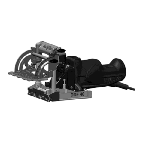
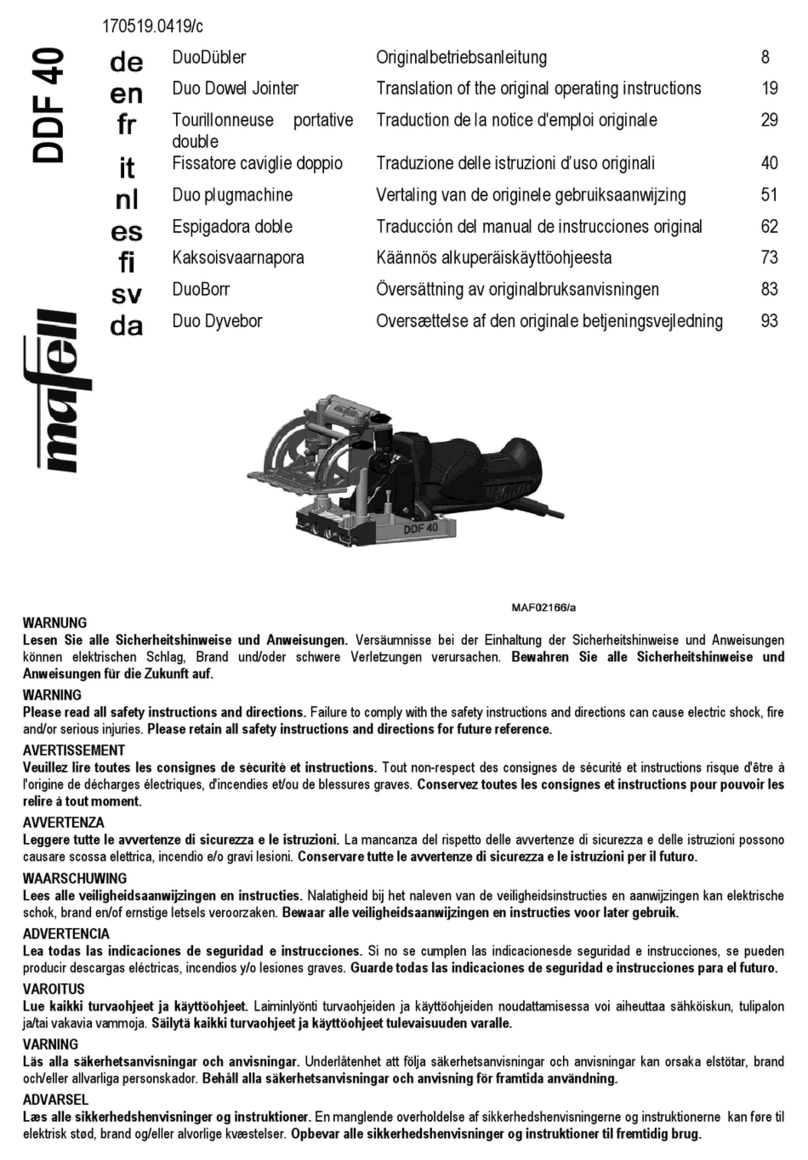
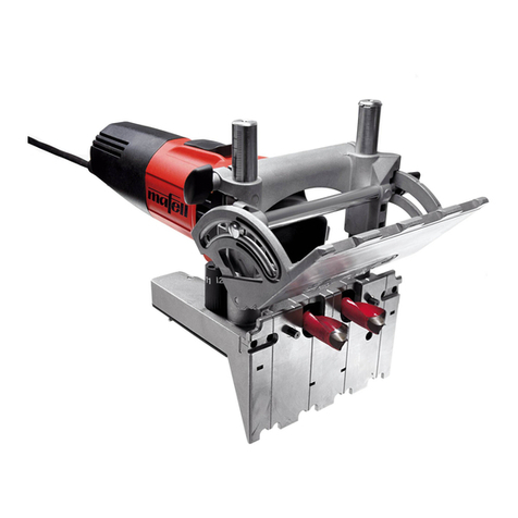
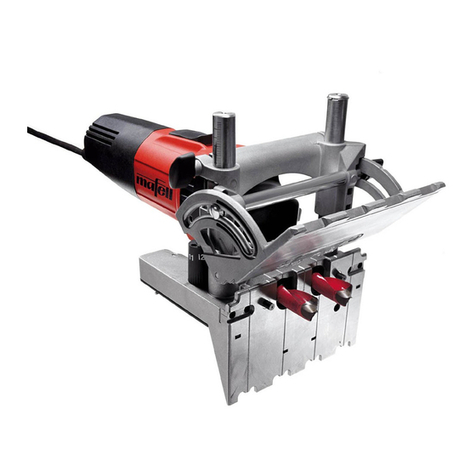
Mafell DD40G User manual

DD40G / DD40P
077039.0317/k
DuoDübler Originalbetriebsanleitung 5
Duo Dowel Jointer Original operating instructions 13
Tourillonneuse portative
double
Traduction de la notice d'emploi originale 21
Fissatore caviglie doppio Istruzioni per l'uso originali 29
Duo plugmachine Originele gebruiksaanwijzing 38
Espigadora doble Manual de instrucciones original 46
Kaksoisvaarnapora Alkuperäiskäyttöohje 55
DuoBorr Originalbruksanvisning 63
Duo Dyvebor Original driftsvejledning 71
WARNUNG
Lesen Sie alle Sicherheitshinweise und Anweisungen. Versäumnisse bei der Einhaltung der Sicherheitshinweise und Anweisungen
können elektrischen Schlag, Brand und/oder schwere Verletzungen verursachen. Bewahren Sie alle Sicherheitshinweise und
Anweisungen für die Zukunft auf.
WARNING
Please read all safety instructions and directions. Failure to comply with the safety instructions and directions can cause electric shock, fire
and/or serious injuries. Please retain all safety instructions and directions for future reference.
AVERTISSEMENT
Veuillez lire toutes les consignes de sécurité et instructions. Tout non-respect des consignes de sécurité et instructions risque d'être à
l'origine de décharges électriques, d'incendies et/ou de blessures graves. Conservez toutes les consignes et instructions pour pouvoir les
relire à tout moment.
AVVERTENZA
Leggere tutte le avvertenze di sicurezza e le istruzioni. La mancanza del rispetto delle avvertenze di sicurezza e delle istruzioni possono
causare scossa elettrica, incendio e/o gravi lesioni. Conservare tutte le avvertenze di sicurezza e le istruzioni per il futuro.
WAARSCHUWING
Lees alle veiligheidsaanwijzingen en instructies. Nalatigheid bij het naleven van de veiligheidsinstructies en aanwijzingen kan elektrische
schok, brand en/of ernstige letsels veroorzaken. Bewaar alle veiligheidsaanwijzingen en instructies voor later gebruik.
ADVERTENCIA
Lea todas las indicaciones de seguridad e instrucciones. Si no se cumplen las indicacionesde seguridad e instrucciones, se pueden
producir descargas eléctricas, incendios y/o lesiones graves. Guarde todas las indicaciones de seguridad e instrucciones para el futuro.
VAROITUS
Lue kaikki turvaohjeet ja käyttöohjeet. Laiminlyönti turvaohjeiden ja käyttöohjeiden noudattamisessa voi aiheuttaa sähköiskun, tulipalon
ja/tai vakavia vammoja. Säilytä kaikki turvaohjeet ja käyttöohjeet tulevaisuuden varalle.
VARNING
Läs alla säkerhetsanvisningar och anvisningar. Underlåtenhet att följa säkerhetsanvisningar och anvisningar kan orsaka elstötar, brand
och/eller allvarliga personskador. Behåll alla säkerhetsanvisningar och anvisning för framtida användning.
ADVARSEL
Læs alle sikkerhedshenvisninger og instruktioner. En manglende overholdelse af sikkerhedshenvisningerne og instruktionerne kan føre til
elektrisk stød, brand og/eller alvorlige kvæstelser. Opbevar alle sikkerhedshenvisninger og instruktioner til fremtidig brug.


-13-
English
Table of Contents
1 Signs and symbols ......................................................................................................... 14
2 Product information ........................................................................................................ 14
2.1 Manufacturer´s data .......................................................................................................14
2.2 Machine identification..................................................................................................... 14
2.3 Technical data ................................................................................................................15
2.4 Noise emission specifications ........................................................................................ 15
2.5 Vibration specifications................................................................................................... 15
2.6 Scope of supply.............................................................................................................. 15
2.7 Safety devices ................................................................................................................ 16
2.8 Use according to intended purpose................................................................................ 16
2.9 Residual risks ................................................................................................................. 16
3 Safety instructions .......................................................................................................... 17
4 Setting / Adjustment ....................................................................................................... 17
4.1 Mains connection ........................................................................................................... 17
4.2 Chip extraction ............................................................................................................... 17
4.3 Selection of tools ............................................................................................................ 17
4.4 Tool change....................................................................................................................17
4.5 Pivot adjustment............................................................................................................. 18
4.6 Drill depth adjustment..................................................................................................... 18
4.7 Adjusting the drilling clearance....................................................................................... 18
5 Operation........................................................................................................................18
5.1 Initial operation ...............................................................................................................18
5.2 Switching on and off ....................................................................................................... 18
5.3 Drilling according to tracing ............................................................................................ 18
5.4 Drilling with stop pin .......................................................................................................19
5.5 Drilling with additional stop.............................................................................................19
6 Service and maintenance............................................................................................... 19
6.1 Storage........................................................................................................................... 19
7 Troubleshooting.............................................................................................................. 19
8 Optional accessories ...................................................................................................... 20
9 Exploded drawing and spare parts list ...........................................................................20

-14-
1 Signs and symbols
This symbol appears at places where you will find instructions for your
own safety.
Non-compliance with these instructions may result in very serious injuries.
This symbol indicates a potentially hazardous situation.
If this situation is not avoided, the product or objects in its vicinity may get
damaged.
This symbol indicates tips for the user and other useful information.
2 Product information
for machines with product no. 916001, 916002, 916010, 916020, 916021, 916025, 916030, 916031, 916032,
916033, 916034, 916035, 916040, 916041, 916042, 916043, 916045
2.1 Manufacturer´s data
MAFELL AG, Beffendorfer Straße 4, D-78727 Oberndorf / Neckar, Phone +49 (0)7423/812-0, Fax +49
(0)7423/812-218
2.2 Machine identification
All details required for machine identification are available on the attached rating plate.
Protection class II
CE symbol to document compliance with the basic safety and health
requirements according to Appendix I of the Machinery Directive.
For EU countries only
Do not dispose of electric tools together with household waste material!
In accordance with the European directive 2002/96/EC on waste electrical and
electronic equipment and transposition into national law, obsolete electrical
tools must be collected separately and recycled in an environmentally-
compatible manner.
To reduce the risk of injury, please read the operating instructions.

-15-
2.3 Technical data
DD40P DD40G
Universal motor, radio and TV
interference suppressed
230 V~, 50 Hz or 110 V~, 50
Hz
230 V~, 50 Hz or 110 V~, 50
Hz
Power input (nominal load) 1000 W 700 W
Current at nominal load 4,3 A (230 V) or 9,1 A (110 V) 3,0 A (230 V) or 6,4 A (110 V)
Drill clearance 32 mm (1 1/4 in.) 32 mm (1 1/4 in.)
Drilling depth 0 - 40 mm (0 - 1 9/16 in.) 0 - 37 mm (0- 17/16 in.)
Swivel range 0 - 90° 0 - 90°
Tool diameter maximum
Tool diameter minimum
16 mm (5/8 in.)
6 mm (15/64 in.)
12 mm (15/32 in.)
3 mm (1/8 in.)
Tool receiving bore 8 mm (5/16 in.) 8 mm (5/16 in.)
Tool idling speed 13500 rpm 18500 rpm
Hose connector diameter 35 mm (1 3/8 in.) 35 mm (1 3/8 in.)
Weight without mains cable 2,8 kg 2.8 kg (6.2 lbs)
Dimensions (W x L x H) 130 x 300 x 185 mm (5 1/8 x
11 13/16 x 7 1/4 in.)
130 x 300 x 185 mm (5 1/8 x
11 13/16 x 7 1/4 in.)
2.4 Noise emission specifications
Noise emission values determined according to EN 60745-1:
Sound power level Workplace-related emission value
Idling 100 dB (A) 89 dB (A)
The noise measurement was recorded using the tool included in the standard equipment.
The values stated do not take into consideration any possible series variances and are not suitable for
determining the rating levels, as these fluctuate in dependence on the time in service, the respective type of
machining and the environmental influences. The noise rating level can therefore only be determined on an
individual basis at the machine user's position.
2.5 Vibration specifications
The typical hand-arm vibration is less than 2.5 m/s2.
2.6 Scope of supply
DD40G MidiMAX
Item No. 916001, 916020, 916021, 916025
2 carbide-tipped dowel drill bits ø 8 mm (5/16 in.)
1 pack of MAFELL special dowels ø 8x30 mm (5/16 x
1 3/16 in.)
(approx. 200 pcs.)
1 bottle of glue
2 anti-slip mats
1 Allen key with handle
1 service tool in bracket on the machine
1 carrying case
1 operating manual
1 folder “Safety Instructions”
DD40G MaxiMAX
Item No. 916002, 916030, 916031, 916032, 916033,
916034, 916035
2 carbide-tipped dowel drill bits ø 6 mm (1/4 in.)
2 carbide-tipped dowel drill bits ø 8 mm (5/16 in.)
2 carbide-tipped dowel drill bits ø 10 mm (3/8 in.)
1 pack of MAFELL special dowels ø 6x30 mm (1/4 x
1 3/16 in.)
(approx. 350 pcs.)

-16-
1 pack of MAFELL special dowels ø 8x30 mm (5/16 x
1 3/16 in.)
(approx. 200 pcs.)
1 pack of MAFELL special dowels ø 10x40 (3/8 mm x
1 9/16 in.)
(approx. 100 pcs.)
Further scope of delivery:
1 bottle of glue
1 dowel nozzle ø 8 mm (5/16 in.)
2 anti-slip mats
1 Allen key with handle
1 service tool in bracket on the machine
1 carrying case
1 operating manual
1 folder “Safety Instructions”
DD40P PowerMAX
Item No. 916010, 916040, 916041, 916042, 916043,
916045
2 carbide-tipped dowel drill bits ø 8 mm (5/16 in.)
2 carbide-tipped dowel drill bits ø 10 mm (25/64 in.)
2 carbide-tipped dowel drill bits ø 12 mm (15/32 in.)
1 pack of MAFELL special dowels ø 8x30 mm (5/16 x
1 3/16 in.)
1 pack of MAFELL special dowels ø 10x40 mm (3/8 x
1 9/16 in.)
1 pack of MAFELL special dowels ø 12x60 mm (1/2 x
2 3/8 in.)
Further scope of delivery as MaxiMAX
2.7 Safety devices
Danger
These devices are required for the
machine's safe operation and may
not be removed or rendered
inoperative.
The machine is equipped with the following safety
devices:
-Protection against contact with the bits
-Large bearing faces of limit stops
-Handles and handle supports
-Hose connector
2.8 Use according to intended purpose
The DuoDübler is exclusively intended for drilling of
solid wood and panel materials such as chip board,
coreboard and Mdf-boards, using the drill bits
permitted, with diameters between 3 mm and 12 mm
(1/8 and 15/32 in.) (DD40G) and from 6 mm to 16 mm
(15/64 and 5/8 in.) (DD40P).
Any other use than described above is not
permissible. The manufacturer cannot be held liable
for any damage arising from such other use.
In order to use the machine as intended, comply with
the operating, maintenance, and repair instructions
specified by Mafell.
2.9 Residual risks
Danger
Even if used in accordance with its
intended purpose and despite
conforming with the safety
instructions, residual risks caused
by the intended use will always
remain.
-Touching the drill bits when fitted in or when
outside the base plate.
-Touching the drill bits on the workpiece rear when
drilling.
-Breakage of the drills and risk of the drill bits or
parts of them being hurled away.
-Touching live parts with the housing open and the
mains plug not removed.
-Hearing can be impaired when working for long
periods without ear protectors.
-Emission of harmful wood dusts during longer
operation without extraction.

-17-
3 Safety instructions
Danger
Always observe the following safety
instructions and the safety
regulations applicable in the
respective country of use!
General instructions:
-Children and adolescents must not operate this
machine. This rule does not apply to young
persons receiving training and being supervised by
an expert.
-Never work without the protection devices
prescribed for the respective operating sequence
and do not make any changes to the machine that
could impair safety.
-When operating the machine outdoors, use of an
earth-leakage circuit-breaker is recommended.
-Damaged cables or plugs must be immediately
replaced.
-Avoid sharp bends in the cable. Especially when
transporting and storing the machine, do not wind
the cable around the machine.
Do not use:
-Damaged drill bits and drill bits that have changed
their form.
-Blunt drill bits as they impose an excessive load on
the motor.
-Drill bits that are not suitable for the drill's idling
speed.
Instructions on the use of personal protective
equipment:
-Always wear ear protectors during work.
-Always where a dust mark during work.
Instructions on operation:
-Do not reach with your hands into the drilling area
and do not touch the drill bits. With your other
hand, support the supplementary handle or the
motor casing.
-Do not reach under the workpiece.
-Never support the workpiece in your hand or over
your leg. Secure the workpiece against a sturdy
support.
-Only hold the device by its isolated handle
surfaces when carrying out work during which the
cutting tool could hit hidden power cables or its
own connection cable.
-Before starting to drill, tighten the drilling depth and
cutting angle adjustments.
-Examine the workpiece for foreign objects. Never
attempt to drill into nails or other metal objects.
Instructions on service and maintenance:
-Regularly cleaning the machine, especially the
adjusting devices and guides, constitutes an
important safety factor.
-Only original MAFELL spare parts and accessories
may be used. Otherwise, the manufacturer will not
accept any warranty claims and cannot be held
liable.
4 Setting / Adjustment
4.1 Mains connection
Prior to commissioning make sure that the mains
voltage complies with the operating voltage stated on
the machine's rating plate.
4.2 Chip extraction
Connect the machine to a suitable external dust
extractor during all work generating a considerable
amount of dust. The air velocity must be at least 20
m/s (65.6 ft / sec.).
The inside diameter of hose connector 1 (Fig. 1) is 35
mm (1 3/8 in.).
4.3 Selection of tools
Use the dowel drill bits listed in chapter 8 "Special
Accessories".
These carbide-tipped drills were developed specially
for the DD40G/P and are suitable for all types of
wood.
4.4 Tool change
Danger
Pull the power plug during all
service work.
The basic requirement for correct drilling are well
ground drill bits.
Proceed as follows for the tool change:

-18-
Turn the tool holding fixture 2 (Fig. 2) such that
the screws 3 are on top.
Unfasten the screws with the Allen key.
Pull off the drill bits 4 to the front.
Push the new drill bits into the tool holding
fixture up to the limit stop. Align the plain
surface of the drill bits with the screw holes.
Tighten the screws against the plain surfaces.
Check the drill bits' seat.
After the tool change, you have to
readjust the zero setting for the drill
depth.
Unfasten the wing nut 11 (Fig. 3)
Completely swing open the tilting stop 9.
Tighten the wing nut 11.
Place the machine with the swung open limit
stop onto a flat surface.
Push the motor casing 5 forward until the tip of
the drill bears on this surface.
Unfasten the wing screw 6.
Push the depth stop 7 up to the limit stop to the
top and tighten the wing screw.
Push the indicator 8 to zero.
4.5 Pivot adjustment
The tilting stop 9 (Fig. 3) can be
continuously adjusted in the range
from 0° to 90°. Three latching
positions facilitate a fast setting of
the angles 22.5°, 45° and 67.5°.
Unfasten the wing screw 11.
Tilt the tilting stop to the desired angle.
Retighten the wing nut.
4.6 Drill depth adjustment
The drill depth can be continuously
adjusted in a range between 0 - 37
mm (0 - 1 7/16in.) on the DD40G or
0 - 40 mm (0 - 1 9/16 in.) on the
DD40P.
Unfasten the wing nut 6 (Fig. 3)
Push the depth stop 7 to the desired value.
Retighten the wing nut.
4.7 Adjusting the drilling clearance
The edge clerance is continuously
variable between 7 and 40 mm
(9/32 and 1 9/16 in.).
Unfasten the wing nut 16 (Fig. 4)
Push the tilting stop 9 (Fig. 3) to the desired
scale value.
Retighten the wing nut.
With the rotating revolver limit stop 17 you can select
five firmly preset edge clearances:
6.5 mm, 8 mm, 9.5 mm, 11 mm, 12.5 mm (1/4 in.,
5/16 in., 3/8 in., 7/16 in., 1/2 in.)
5 Operation
5.1 Initial operation
Personnel entrusted to work with the machine must
be made aware of the operating instructions, calling
particular attention to the chapter "Safety
instructions".
5.2 Switching on and off
Switching on: Push the switch 23 (Fig. 5)
forward until it engages.
Switching off: Push onto the rear end of the
switch. The switch jumps into off position.
5.3 Drilling according to tracing
The tilting stop 9 (Fig. 3) has three reference
markings. The reference markings on the left and
right each correspond to the centre of the drill.
Clamp the workpiece or prevent it from moving
by using the anti-slip mats supplied.
Position the machine on the workpiece and align
the machine by means of the reference
markings.
With your free hand, press the tilting stop
against the workpiece.
-19-
Switch on the machine (see chapter 5.2) and
push the motor casing forward up to the limit
stop.
Pull back the motor casing and switch off the
machine.
5.4 Drilling with stop pin
The base plate 22 (Fig. 5) is equipped with two
resilient stop pins. They are used to place the drill
holes at a fixed distance to the outer edge of the
workpiece. The machine stop can be positioned at
the left or right.
Clamp the workpiece or prevent it from moving
by using the anti-slip mats supplied.
Position the machine on the workpiece. At the
same time you push in a stop pin 20 and allow
the other stop pin to butt at the outer edge of the
workpiece.
With your free hand, press the tilting stop
against the workpiece.
Switch on the machine (see chapter 5.2) and
push the motor casing forward up to the limit
stop.
Pull back the motor casing and switch off the
machine.
5.5 Drilling with additional stop
see page 77
6 Service and maintenance
Danger
Pull the power plug during all
service work.
MAFELL machines are designed to be low in
maintenance.
The ball bearings used are greased for life. When the
machine has been in operation for a longer period of
time, we recommend to hand the machine in at an
authorised MAFELL customer service shop for
inspection.
Only use our special grease, order No. 049040 (1 kg
tin) for all greasing points.
6.1 Storage
If the machine is not used for a longer period of time,
it has to be carefully cleaned. Spray bright metal parts
with a rust inhibitor.
7 Troubleshooting
Danger
Determining the causes for existing defects and eliminating these always
requires increased attention and caution. Pull the mains plug beforehand!
Some of the most frequent defects and their causes are listed in the following chart. In case of other defects,
contact your dealer or the MAFELL customer service.
Defect Cause Elimination
No mains voltage Check power supply
Mains fuse defective Replace fuse
Machine cannot be switched on
Carbon brushes worn Take the machine to a MAFELL
customer service shop
Machine stops while drilling is in
process
Mains failure Check mains back-up fuses
Burn marks on the drill holes Blunt drill bit Regrind drill bit or replace
Wood is too dampChip ejection blocked
Extended drilling without
extraction
Connect to an external exhaustion,
e.g. portable dust extractor

-20-
8 Optional accessories
-Dowel drill bit - HS-TiN Ø 3 mm (1/8 in.) Order No. 090 083
-Dowel drill bit - HM Ø 5 mm (13/64 in.) Order No. 090 089
-Dowel drill bit - HM Ø 6 mm (15/64 in.) Order No. 090 096
-Dowel drill bit - HM Ø 6.1 mm (1/4 in.) Order No. 090 120
-Dowel drill bit - HM Ø 7 mm (9/32 in.) Order No. 090 121
-Dowel drill bit - HM Ø 8 mm (5/16 in.) Order No. 090 097
-Dowel drill bit - HM Ø 8.1 mm (5/16 in.) Order No. 090 122
-Dowel drill bit - HM Ø 8.2 mm (21/64 in.) Order No. 090 123
-Dowel drill bit - HM Ø 10 mm (25/64 in.) Order No. 090 098
-Dowel drill bit - HM Ø 10.1 mm (25/64 in.) Order No. 090 124
-Dowel drill bit - HM Ø 10.2 mm (13/32 in.) Order No. 090 125
-Dowel drill bit - HM Ø 12 mm (15/32 in.) Order No. 090 099
-Dowel drill bit - HM Ø 12.1 mm (15/32 in.) Order No. 090 126
-Dowel drill bit - HM Ø 12.2 mm (31/64 in.) Order No. 090 127
-Dowel drill bit - HM Ø 14 mm (35/64 in.) (only for DD40P) Order No. 090 128
-Dowel drill bit - HM Ø 15 mm (19/32 in.) (only for DD40P) Order No. 090 129
-Dowel drill bit - HM Ø 16 mm (5/8 in.) (only for DD40P) Order No. 090 085
-Dowel drill bit - HM Ø 16.2 mm (41/64 in.) (only for DD40P) Order No. 090 130
-dowel gauge with clamping device Order No. 203 980
-Dowel drilling template extension 1600 cpl., length 1600 mm (63 in.) Order No. 203 434
-Adaptor for dowel template extension Order No. 203 437
-MAFELL special dowels Ø 6x30 mm (1/4 x 1 3/16 in.), 6 x 350 pcs. Order No. 802 000
-MAFELL special dowels Ø 8x30 mm (5/16 x 1 3/16 in.), 6 x 200 pcs. Order No. 802 010
-MAFELL special dowels Ø 8x40 mm (5/16 x 1 9/16 in.), 6 x 120 pcs. Order No. 802 011
-MAFELL special dowels Ø 10x40 mm (3/8 x 1 9/16 in.), 6 x 100 pcs. Order No. 802 020
-MAFELL special dowels Ø 10x60 mm (3/8 x 2 3/8 in.), 6 x 50 pcs. Order No. 802 021
-MAFELL special dowels Ø 12x60 mm (1/2 x 2 3/8 in.), 6 x 40 pcs. Order No. 802 030
-MAFELL special dowels Ø 16x75 mm (63/100 x 2 19/20 in.), 6 x 30 pcs. Order No. 802 040
-Dowel nozzle ø 8 mm (5/16 in.) Order No. 095 060
-Bottle of glue Order No. 095 059
-Anti-slip mat wrapped, 2 pcs. Order No. 095 063
-Allen key with handle Order No. 093 282
9 Exploded drawing and spare parts list
The corresponding information in respect of spare parts can be found on our homepage: www.mafell.com
Other manuals for DD40G
1
This manual suits for next models
1
Table of contents
Other Mafell Power Tools manuals

Mafell
Mafell DDF 40 Quick guide

Mafell
Mafell FM 800 User manual

Mafell
Mafell DDF 40 Quick guide

Mafell
Mafell P1CC Series Guide

Mafell
Mafell DD40P Assembly instructions

Mafell
Mafell LNF 20 User manual

Mafell
Mafell LO 65 Ec User manual

Mafell
Mafell DD40G User manual

Mafell
Mafell FM 800 Quick guide

Mafell
Mafell KSP 55 Guide