Makita M3600 User manual

M3600
EN Router INSTRUCTION MANUAL 8
SL Rezkar NAVODILA ZA UPORABO 15
SQ Freza MANUALI I PËRDORIMIT 22
BG Фреза РЪКОВОДСТВО ЗА
ЕКСПЛОАТАЦИЯ 29
HR Glodalica PRIRUČNIK S UPUTAMA 37
МК Глодач УПАТСТВО ЗА УПОТРЕБА 44
SR Глодалица УПУТСТВО ЗА УПОТРЕБУ 51
RO Maşină de frezat verticală MANUAL DE INSTRUCŢIUNI 58
UK Фрезер ІНСТРУКЦІЯ З
ЕКСПЛУАТАЦІЇ 65
RU Фрезер РУКОВОДСТВО ПО
ЭКСПЛУАТАЦИИ 72

1
2
3
4
5
6
Fig.1
1
Fig.2
1
2
3
4
5
Fig.3
1
Fig.4
1
2
Fig.5
1
Fig.6
1
2
3
4
4
2
Fig.7
1
23
4
Fig.8
2

1
2
B
3
A
Fig.9
1
2
Fig.10
C1
A
B
2
Fig.11
Fig.12
1
2
3
Fig.13
1
2
3
4
5
6
7
Fig.14
1
2
3
4
B
A
C
Fig.15
1
2
B
A
C
Fig.16
3

3
1
2
Fig.17
1
2
Fig.18
12
3
Fig.19
1
Fig.20
1
2
Fig.21
Fig.22
1
Fig.23
1
Fig.24
4

1
Fig.25
Fig.26
R
Fig.27
Fig.28
Fig.29
Fig.30
Fig.31
Fig.32
5

Fig.33
Fig.34
Fig.35
Fig.36
Fig.37
Fig.38
Fig.39
6

Fig.40
Fig.41
Fig.42
Fig.43
Fig.44
Fig.45
7

8ENGLISH
ENGLISH (Original instructions)
SPECIFICATIONS
Model: M3600
Collet chuck capacity 12 mm or 1/2″
Plunge capacity 0 - 60 mm
No load speed 22,000 min-1
Overall height 300 mm
Net weight 5.5 kg
Safety class /II
• Due to our continuing program of research and development, the specications herein are subject to change
without notice.
• Specications may differ from country to country.
• Weight according to EPTA-Procedure 01/2003
Intended use
The tool is intended for ush trimming and proling of
wood, plastic and similar materials.
Power supply
The tool should be connected only to a power supply of
the same voltage as indicated on the nameplate, and
can only be operated on single-phase AC supply. They
are double-insulated and can, therefore, also be used
from sockets without earth wire.
For public low-voltage distribution
systems of between 220 V and
250 V.
Switching operations of electric apparatus cause volt-
age uctuations. The operation of this device under
unfavorable mains conditions can have adverse effects
to the operation of other equipment. With a mains
impedance equal or less than 0.35 Ohms it can be pre-
sumed that there will be no negative effects. The mains
socket used for this device must be protected with a
fuse or protective circuit breaker having slow tripping
characteristics.
Noise
The typical A-weighted noise level determined accord-
ing to EN60745:
Sound pressure level (LpA) : 86 dB(A)
Sound power level (LWA) : 97 dB (A)
Uncertainty (K) : 3 dB(A)
WARNING: Wear ear protection.
Vibration
The vibration total value (tri-axial vector sum) deter-
mined according to EN60745:
Work mode: cutting grooves in MDF
Vibration emission (ah) : 2.5 m/s2
Uncertainty (K) : 1.5 m/s2
NOTE: The declared vibration emission value has
been measured in accordance with the standard test
method and may be used for comparing one tool with
another.
NOTE: The declared vibration emission value
may also be used in a preliminary assessment of
exposure.
WARNING: The vibration emission during actual
use of the power tool can differ from the declared
emission value depending on the ways in which the
tool is used.
WARNING: Be sure to identify safety measures
to protect the operator that are based on an estima-
tion of exposure in the actual conditions of use (taking
account of all parts of the operating cycle such as
the times when the tool is switched off and when it is
running idle in addition to the trigger time).
EC Declaration of Conformity
For European countries only
Makita declares that the following Machine(s):
Designation of Machine: Router
Model No./ Type: M3600
Conforms to the following European Directives:
2006/42/EC
They are manufactured in accordance with the following
standard or standardized documents: EN60745
The technical le in accordance with 2006/42/EC is
available from:
Makita, Jan-Baptist Vinkstraat 2, 3070, Belgium
4.8.2015
Yasushi Fukaya
Director
Makita, Jan-Baptist Vinkstraat 2, 3070, Belgium

9ENGLISH
General power tool safety warnings
WARNING: Read all safety warnings and
all instructions. Failure to follow the warnings and
instructions may result in electric shock, re and/or
serious injury.
Save all warnings and instruc-
tions for future reference.
The term "power tool" in the warnings refers to your
mains-operated (corded) power tool or battery-operated
(cordless) power tool.
Router safety warnings
1. Hold power tool by insulated gripping sur-
faces, because the cutter may contact its own
cord. Cutting a “live” wire may make exposed
metal parts of the power tool “live” and shock the
operator.
2. Use clamps or another practical way to secure
and support the workpiece to a stable plat-
form. Holding the work by your hand or against
the body leaves it unstable and may lead to loss of
control.
3. Wear hearing protection during extended
period of operation.
4. Handle the router bits very carefully.
5. Check the router bit carefully for cracks or
damage before operation. Replace cracked or
damaged bit immediately.
6. Avoid cutting nails. Inspect for and remove all
nails from the workpiece before operation.
7. Hold the tool rmly with both hands.
8. Keep hands away from rotating parts.
9. Make sure the router bit is not contacting the
workpiece before the switch is turned on.
10. Before using the tool on an actual workpiece,
let it run for a while. Watch for vibration or
wobbling that could indicate improperly
installed bit.
11. Be careful of the router bit rotating direction
and the feed direction.
12. Do not leave the tool running. Operate the tool
only when hand-held.
13. Always switch off and wait for the router bit to
come to a complete stop before removing the
tool from workpiece.
14. Do not touch the router bit immediately after
operation; it may be extremely hot and could
burn your skin.
15. Do not smear the tool base carelessly with
thinner, gasoline, oil or the like. They may
cause cracks in the tool base.
16. Use router bits of the correct shank diameter
suitable for the speed of the tool.
17. Some material contains chemicals which may
be toxic. Take caution to prevent dust inhala-
tion and skin contact. Follow material supplier
safety data.
18. Always use the correct dust mask/respirator
for the material and application you are work-
ing with.
SAVE THESE INSTRUCTIONS.
WARNING: DO NOT let comfort or familiarity
with product (gained from repeated use) replace
strict adherence to safety rules for the subject
product. MISUSE or failure to follow the safety
rules stated in this instruction manual may cause
serious personal injury.
FUNCTIONAL
DESCRIPTION
CAUTION: Always be sure that the tool is
switched off and unplugged before adjusting or
checking function on the tool.
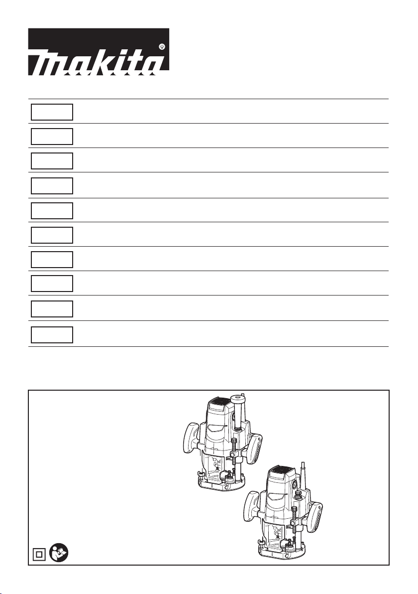
Adjusting the depth of cut
Place the tool on a at surface. Loosen the lock lever
and lower the tool body until the router bit just touches
the at surface. Press the lock lever down to lock the
tool body. While pressing the fast-feed button, move the
stopper pole up or down until the desired depth of cut is
obtained. Minute depth adjustments can be obtained by
turning the stopper pole (1.5 mm (1/16″) per turn).
► Fig.1: 1. Nylon nut 2. Stopper pole 3. Fast-feed
button 4. Adjusting hex bolt 5. Stopper
6. Lock lever
CAUTION: The depth of cut should not be
more than 20 mm (13/16″) at a pass when cutting
grooves. For extra-deep grooving operations,
make two or three passes with progressively
deeper router bit settings.
Nylon nut
For tool without the knob
The upper limit of the tool body can be adjusted by
turning the nylon nut. Do not lower the nylon nut too low.
The router bit will protrude dangerously.
For tool with the knob
By turning the knob, the upper limit of the tool body can
be adjusted. When the tip of the router bit is retracted
more than required in relation to the base plate surface,
turn the knob to lower the upper limit. Do not lower the
knob too low. The router bit will protrude dangerously.
► Fig.2: 1. Knob
CAUTION: Since excessive cutting may cause
overload of the motor or difculty in controlling
the tool, the depth of cut should not be more than
20 mm (13/16″) at a pass when cutting grooves.
When you wish to cut grooves more than 20 mm
(13/16″) deep, make several passes with progres-
sively deeper router bit settings.
CAUTION: Do not lower the knob too low. The
router bit will protrude dangerously.

10 ENGLISH
Stopper block
As the rotary stopper has three adjusting hex bolts, you
can easily obtain three different depths of cut without
readjusting the stopper pole. To adjust the hex bolts,
loosen the hex nuts on them and turn the hex bolts.
After obtaining the desired position, tighten the hex nuts
to secure the hex bolts.
► Fig.3: 1. Stopper pole 2. Chip deector 3. Stopper
4. Adjusting hex bolt 5. Hex nut
Switch action
CAUTION: Before plugging in the tool, always
check to see that the tool is switched off.
CAUTION: Make sure that the shaft lock is
released before the switch is turned on.
To start the tool, move the switch lever to the I position.
To stop the tool, move the switch lever to the O position.
► Fig.4: 1. Switch lever
CAUTION: Hold the tool rmly when turning
off the tool, to overcome the reaction.
ASSEMBLY
CAUTION: Always be sure that the tool is
switched off and unplugged before carrying out
any work on the tool.
Installing or removing the router bit
Insert the router bit all the way into the collet cone.
Press the shaft lock to keep the shaft stationary and
use the wrench to tighten the collet nut securely. When
using router bits with smaller shank diameter, rst insert
the appropriate collet sleeve into the collet cone, then
install the router bit as illustrated.
To remove the router bit, follow the installation proce-
dure in reverse.
► Fig.5: 1. Shaft lock 2. Wrench
CAUTION: Install the router bit securely.
Always use only the wrench provided with the
tool. A loose or overtightened router bit can be
dangerous.
CAUTION: Do not tighten the collet nut with-
out inserting a router bit or install small shank
bits without using a collet sleeve. Either can lead
to breakage of the collet cone.
OPERATION
CAUTION: Before operation, always make
sure that the tool body automatically rises to
the upper limit and the router bit does not pro-
trude from the tool base when the lock lever is
loosened.
CAUTION: Before operation, always make
sure that the chip deector is installed properly.
► Fig.6: 1. Chip deector
Set the tool base on the workpiece to be cut without
the router bit making any contact. Then turn the tool on
and wait until the router bit attains full speed. Lower the
tool body and move the tool forward over the workpiece
surface, keeping the tool base ush and advancing
smoothly until the cutting is complete.
When doing edge cutting, the workpiece surface should
be on the left side of the router bit in the feed direction.
► Fig.7: 1. Workpiece 2. Bit revolving direction
3. View from the top of the tool 4. Feed
direction
NOTE: Moving the tool forward too fast may cause
a poor quality of cut, or damage to the router bit or
motor. Moving the tool forward too slowly may burn
and mar the cut. The proper feed rate will depend on
the router bit size, the kind of workpiece and depth
of cut.
Before beginning the cut on the actual workpiece, it
is advisable to make a sample cut on a piece of scrap
lumber. This will show exactly how the cut will look as
well as enable you to check dimensions.
NOTE: When using the straight guide or the trimmer
guide, be sure to install it on the right side in the feed
direction. This will help to keep it ush with the side of
the workpiece.
► Fig.8: 1. Feed direction 2. Router bit revolving
direction 3. Workpiece 4. Straight guide
Straight guide
The straight guide is effectively used for straight cuts
when chamfering or grooving.
Straight guide (Type A)
Optional accessory
Install the straight guide on the guide holder with the
thumb screw (B). Insert the guide holder into the holes
in the tool base and tighten the thumb screw (A). To
adjust the distance between the router bit and the
straight guide, loosen the thumb screw (B) and turn the
ne adjusting screw. At the desired distance, tighten the
thumb screw (B) to secure the straight guide in place.
► Fig.9: 1. Guide holder 2. Fine adjusting screw
3. Straight guide
Straight guide (Type B)
Optional accessory
Insert the straight guide into the holes in the tool base
and tighten the thumb screw. To adjust the distance
between the router bit and the straight guide, loosen the

11 ENGLISH
thumb screw. At the desired distance, tighten the thumb
screw to secure the straight guide in place.
Wider straight guide of desired dimensions may be
made by using the convenient holes in the guide to bolt
on extra pieces of wood.
► Fig.10: 1. Thumb screw 2. Straight guide
When using a large diameter router bit, attach pieces
of wood to the straight guide which have a thickness of
more than 15 mm (5/8″) to prevent the router bit from
striking the straight guide.
When cutting, move the tool with the straight guide ush
with the side of the workpiece.
► Fig.11: 1. Straight guide 2. Wood
A=55 mm (2-3/16″)
B=55 mm (2-3/16″)
C=15 mm (5/8″) or thicker
Templet guide
The templet guide provides a sleeve through which the
router bit passes, allowing use of the tool with templet
patterns. To install the templet guide, loosen the screws
on the tool base, insert the templet guide and then
tighten the screws.
► Fig.12
Secure the templet to the workpiece. Place the tool on
the templet and move the tool with the templet guide
sliding along the side of the templet.
► Fig.13: 1. Templet guide 2. Screws 3. Base plate
NOTE: The workpiece will be cut a slightly different
size from the templet. Allow for the distance (X)
between the router bit and the outside of the templet
guide. The distance (X) can be calculated by using
the following equation:
Distance (X) = (outside diameter of the templet
guide - router bit diameter) / 2
► Fig.14: 1. Router bit 2. Base 3. Templet
4. Workpiece 5. Distance (X) 6. Outside
diameter of the templet guide 7. Templet
guide
Trimmer guide
Trimming, curved cuts in veneers for furniture and the
like can be done easily with the trimmer guide. The
guide roller rides the curve and assures a ne cut.
Trimmer guide (Type A)
Optional accessory
Install the trimmer guide on the guide holder with the
thumb screw (B). Insert the guide holder into the holes
in the tool base and tighten the thumb screw (A). To
adjust the distance between the router bit and the
trimmer guide, loosen the thumb screw (B) and turn the
ne adjusting screw. When adjusting the guide roller up
or down, loosen the thumb screw (C). After adjusting,
tighten all the thumb screws securely.
► Fig.15: 1. Guide holder 2. Fine adjusting screw
3. Trimmer guide 4. Guide roller
Trimmer guide (Type B)
Optional accessory
Install the trimmer guide on the straight guide with the
thumb screws (B). Insert the straight guide into the
holes in the tool base and tighten the thumb screw (A).
To adjust the distance between the router bit and the
trimmer guide, loosen the thumb screws (B). When
adjusting the guide roller up or down, loosen the thumb
screw (C). After adjusting, tighten all the thumb screws
securely.
► Fig.16: 1. Guide roller 2. Trimmer guide
When cutting, move the tool with the guide roller riding
the side of the workpiece.
► Fig.17: 1. Router bit 2. Guide roller 3. Workpiece
Dust cover (For tool with the knob)
Optional accessory
Dust cover prevents sawdust from being drawn into the
tool in the inverted position.
Install the dust cover as illustrated when using the tool
with a router stand available in the market.
Remove it when using the tool in the normal position.
► Fig.18: 1. Screw 2. Dust cover
Spacer (For tool with the knob)
Optional accessory
The spacer prevents the router bit from dropping into
the chuck when replacing the router bit in the inverted
position.
Insert the spacer as illustrated when using the tool with
a router stand available in the market.
► Fig.19: 1. Collet nut 2. Collet cone 3. Spacer
Dust extraction
Optional accessory
Use the vacuum head for dust extraction.
► Fig.20: 1. Vacuum head
Installing the vacuum head
► Fig.21: 1. Support 2. Lock lever
1. Raise the lock lever of the vacuum head.
2. Place the vacuum head on the tool base so that its
top will be caught in the hook on the tool base.
3. Insert the supports on the vacuum head into the
hooks on the front of the tool base.
4. Push down the lock lever onto the tool base.
5. Connect a vacuum cleaner to the vacuum head.
► Fig.22
Removing the vacuum head
1. Raise the lock lever.
2. Pull the vacuum head out of the tool base while
holding the supports between thumb and nger.

12 ENGLISH
MAINTENANCE
CAUTION: Always be sure that the tool is
switched off and unplugged before attempting to
perform inspection or maintenance.
NOTICE: Never use gasoline, benzine, thinner,
alcohol or the like. Discoloration, deformation or
cracks may result.
Replacing carbon brushes
► Fig.23: 1. Limit mark
Check the carbon brushes regularly.
Replace them when they wear down to the limit mark.
Keep the carbon brushes clean and free to slip in the
holders. Both carbon brushes should be replaced at the
same time. Use only identical carbon brushes.
1. Use a screwdriver to remove the brush holder
caps.
2. Take out the worn carbon brushes, insert the new
ones and secure the brush holder caps.
► Fig.24: 1. Brush holder cap
For tool with the knob
CAUTION: Be sure to re-install the knob after
inserting new carbon brush.
Release the lock lever and remove the knob by turning
it counterclockwise.
► Fig.25: 1. Knob
NOTE: The compression spring will come out of
the knob, so be careful not to lose the compression
spring.
To maintain product SAFETY and RELIABILITY,
repairs, any other maintenance or adjustment should
be performed by Makita Authorized or Factory Service
Centers, always using Makita replacement parts.
OPTIONAL
ACCESSORIES
Router bits
Straight bit
► Fig.26
Unit:mm
D A L1 L2
620 50 15
1/4″
12 12 60 30
1/2″
12 10 60 25
1/2″
8 8 60 25
6 8 50 18
1/4″
6 6 50 18
1/4″
“U”Grooving bit
► Fig.27
Unit:mm
D A L1 L2 R
6 6 50 18 3
“V”Grooving bit
► Fig.28
Unit:mm
D A L1 L2 θ
1/4″ 20 50 15 90°
Dovetail bit
► Fig.29
Unit:mm
D A L1 L2 θ
814.5 55 10 35°
3/8″
814.5 55 14.5 23°
3/8″
812 50 930°
3/8″

13 ENGLISH
Drill point ush trimming bit
► Fig.30
Unit:mm
D A L1 L2 L3
12 12 60 20 35
8 8 60 20 35
6 6 60 18 28
Drill point double ush trimming bit
► Fig.31
Unit:mm
D A L1 L2 L3 L4
6 6 70 40 12 14
Slotting cutter
► Fig.32
Unit:mm
D A L1 L2
12 30 55 6
1/2″
12 30 55 3
1/2″
Board-jointing bit
► Fig.33
Unit:mm
DA1 A2 L1 L2 L3
12 38 27 61 420
Corner rounding bit
► Fig.34
Unit:mm
DA1 A2 L1 L2 L3 R
625 948 13 5 8
620 845 10 4 4
Chamfering bit
► Fig.35
Unit:mm
DA1 A2 L1 L2 L3 C
12 30 20 55 12 20 4
1/2″
► Fig.36
Unit:mm
D A L1 L2 L3 θ
623 46 11 630°
620 50 13 545°
620 49 14 260°
Beading bit
► Fig.37
Unit:mm
DA1 A2 L1 L2 L3 R
12 30 20 55 12 20 4
1/2″
Cove beading bit
► Fig.38
Unit:mm
D A L1 L2 R
620 43 8 4
625 48 13 8
Ball bearing ush trimming bit
► Fig.39
Unit:mm
D A L1 L2
610 50 20
1/4″
Ball bearing corner rounding bit
► Fig.40
Unit:mm
DA1 A2 L1 L2 L3 R
615 837 73.5 3
621 840 10 3.5 6
1/4″ 21 840 10 3.5 6
Ball bearing chamfering bit
► Fig.41
Unit:mm
DA1 A2 L1 L2 θ
626 842 12 45°
1/4″
620 841 11 60°

14 ENGLISH
Ball bearing beading bit
► Fig.42
Unit:mm
DA1 A2 A3 L1 L2 L3 R
620 12 840 10 5.5 4
626 12 842 12 4.5 7
Ball bearing cove beading bit
► Fig.43
Unit:mm
DA1 A2 A3 A4 L1 L2 L3 R
620 18 12 840 10 5.5 3
626 22 12 842 12 5 5
Ball bearing roman ogee bit
► Fig.44
Unit:mm
DA1 A2 L1 L2 L3 R1 R2
620 840 10 4.5 2.5 4.5
626 842 12 4.5 3 6
Double ball bearing round corner bit
► Fig.45
Unit:mm
DA1 A2 A3 L1 L2 L3 R
12 35 27 19 70 11 3.5 3
1/2″

15 SLOVENŠČINA
SLOVENŠČINA (Originalna navodila)
TEHNIČNI PODATKI
Model: M3600
Zmogljivost vpenjalne glave 12 mm ali 1/2″
Zmogljivost ugreznjenja 0 - 60 mm
Hitrost brez obremenitve 22.000 min-1
Skupna višina 300 mm
Neto teža 5,5 kg
Razred zaščite /II
• Ker nenehno opravljamo raziskave in razvijamo svoje izdelke, se lahko tehnični podatki v tem dokumentu
spremenijo brez obvestila.
• Tehnični podatki se lahko razlikujejo od države do države.
• Teža v skladu s postopkom EPTA 01/2003
Predvidena uporaba
Orodje je namenjeno za poravnano prirezovanje in
proliranje lesa, plastike in podobnih materialov.
Priključitev na električno omrežje
Napetost električnega omrežja se mora ujemati s
podatki na tipski ploščici. Stroj deluje samo z enofazno
izmenično napetostjo. Stroj je po evropskih smernicah
dvojno zaščitno izoliran, zato se ga lahko priključi tudi v
vtičnice brez ozemljitvenega voda.
Za javna nizkonapetostna električna
omrežja z napetostjo med 220 V in
250 V.
Vklopi in izklopi električnih aparatov povzročajo nihanje
električne napetosti. Delovanje te naprave v neugodnih
omrežnih pogojih ima lahko neželene učinke na delova-
nje drugih priključenih naprav. Pri impedanci omrežja, ki
je enaka ali manjša od 0,35 Ohma, je možno predposta-
viti, da ne bo negativnih učinkov. Omrežna vtičnica, na
katero bo priključena ta naprava, mora biti zaščitena z
varovalko ali s tokovnim zaščitnim stikalom s počasno
karakteristiko proženja.
Hrup
Običajna A-ovrednotena raven hrupa v skladu z
EN60745:
Raven zvočnega tlaka (LpA): 86 dB (A)
Raven zvočne moči (LWA): 97 dB (A)
Odstopanje (K): 3 dB (A)
OPOZORILO: Uporabljajte zaščito za sluh.
Vibracije
Skupne vrednosti vibracij (vektorska vsota treh osi) v
skladu z EN60745:
Delovni način: rezanje utorov v plošče MDF
Emisije vibracij (ah): 2,5 m/s2
Odstopanje (K): 1,5 m/s2
OPOMBA: Navedena vrednost oddajanja vibracij
je bila izmerjena v skladu s standardnimi metodami
testiranja in se lahko uporablja za primerjavo orodij.
OPOMBA: Navedena vrednost oddajanja vibra-
cij se lahko uporablja tudi pri predhodni oceni
izpostavljenosti.
OPOZORILO: Oddajanje vibracij med dejansko
uporabo električnega orodja se lahko razlikuje od
navedene vrednosti oddajanja, odvisno od načina
uporabe orodja.
OPOZORILO: Upravljavec mora za lastno zaš-
čito poznati varnostne ukrepe, ki temeljijo na oceni
izpostavljenosti v dejanskih pogojih uporabe (poleg
časa proženja je treba upoštevati celoten delovni
cikel, vključno s časom, ko je orodje izklopljeno, in
časom, ko deluje v prostem teku).
ES Izjava o skladnosti
Samo za evropske države
Družba Makita izjavlja, da so naslednji izdelki:
Oznaka stroja: Rezkar
Številka/tip modela: M3600
skladni z naslednjimi evropskimi direktivami:
2006/42/ES
Izdelani so v skladu z naslednjim standardom ali stan-
dardiziranimi dokumenti: EN60745
Tehnična dokumentacija v skladu z direktivo 2006/42/
ES je na voljo na naslovu:
Makita, Jan-Baptist Vinkstraat 2, 3070, Belgija
4.8.2015
Yasushi Fukaya
Direktor
Makita, Jan-Baptist Vinkstraat 2, 3070, Belgija

16 SLOVENŠČINA
Splošna varnostna opozorila za
električno orodje
OPOZORILO: Preberite vsa varnostna opo-
zorila in navodila. Neupoštevanje opozoril in navodil
lahko privede do električnega udara, požara in/ali
resnih telesnih poškodb.
Shranite vsa opozorila in navo-
dila za poznejšo uporabo.
Izraz „električno orodje“ v opozorilih se nanaša na vaše
električno orodje (s kablom) ali baterijsko električno
orodje (brez kabla).
Varnostna opozorila pri uporabi
rezkarja
1. Električno orodje držite samo na izoliranih
držalnih površinah, saj se lahko rezalnik
dotakne lastnega kabla. Ob stiku z vodniki pod
napetostjo dobijo napetost vsi neizolirani kovinski
deli električnega orodja, zaradi česar lahko upo-
rabnik utrpi električni udar.
2. Uporabljajte sponke ali druge praktične načine
za pritrditev in podporo obdelovanca na sta-
bilno podlago. Če držite obdelovanca z roko
ali ga naslanjate na telo, je nestabilen in lahko
povzroči izgubo nadzora.
3. Med daljšo uporabo uporabljajte zaščito za
sluh.
4. Z nastavki rezkarja ravnajte zelo previdno.
5. Pred uporabo skrbno preverite nastavek rez-
karja glede obrabe, razpok ali poškodb. Takoj
zamenjajte počen ali poškodovan nastavek.
6. Izogibajte se rezanju žebljev. Pred delom poi-
ščite in odstranite vse žeblje iz obdelovanca.
7. Orodje trdno držite z obema rokama.
8. Ne približujte rok vrtečim se delom.
9. Preden vklopite stikalo, se prepričajte, ali se
nastavek rezkarja ne dotika obdelovanca.
10. Pred začetkom dela na obdelovancu pustite
orodje delovati nekaj časa v prostem teku.
Bodite pozorni na vibracije ali majanje, ki
bi lahko kazalo na nepravilno nameščen
nastavek.
11. Bodite pozorni na smer vrtenja nastavka rez-
karja in smer pomika.
12. Orodja ne pustite delovati brez nadzora.
Dovoljeno ga je uporabljati samo ročno.
13. Orodje vedno izključite in počakajte, da se
nastavek rezkarja popolnoma ustavi, preden
ga odstranite iz obdelovanca.
14. Takoj po končani obdelavi se ne dotikajte
nastavka rezkarja; ta je lahko zelo vroč in
lahko povzroči opekline kože.
15. Drsnika orodja ne mažite brezbrižno z razred-
čilom, bencinom, oljem ali podobnimi sredstvi.
To lahko povzroči razpoke v drsniku orodja.
16. Uporabite nastavke rezkarja s pravilnim pre-
merom osi, ki so primerni za hitrost orodja.
17. Nekateri materiali vsebujejo kemikalije, ki so
lahko strupene. Bodite previdni ter preprečite
vdihavanje prahu in stik s kožo. Upoštevajte
varnostne podatke dobavitelja materiala.
18. Vedno uporabite ustrezno protiprašno masko/
respirator za načrtovani material in uporabo.
SHRANITE TA NAVODILA.
OPOZORILO: NE dovolite, da bi zaradi udob-
nejšega dela ali znanja o uporabi izdelka (prido-
bljenega z večkratno uporabo) opustili strogo
upoštevanje varnostnih zahtev v okviru pravilne
uporabe orodja. ZLORABA ali neupoštevanje var-
nostnih zahtev v teh navodilih za uporabo lahko
povzroči resne telesne poškodbe.
OPIS DELOVANJA
POZOR: Pred vsako nastavitvijo ali pregle-
dom nastavitev orodja se prepričajte, da je orodje
izklopljeno in izključeno z električnega omrežja.
Nastavitev globine rezanja
Orodje položite na ravno podlago. Popustite zaklepno
ročico in znižajte telo orodja, da se nastavek rezkarja
dotakne ravne površine. Pritisnite zaklepno ročico
navzdol, da ksirate telo orodja. Medtem ko pritiskate
gumb za hitro podajanje, premaknite ustavljalni drog
navzgor ali navzdol, da dosežete želeno globino.
Prilagoditev minimalne globine lahko dosežete z vrte-
njem ustavljalnega droga (1,5 mm (1/16″) na obrat).
► Sl.1: 1. Najlonska matica 2. Ustavljalni drog
3. Gumb za hitro podajanje 4. Prilagoditveni
šestrobi vijak 5. Omejevalnik 6. Zaklepna
ročica
POZOR: Globina reza ne sme biti več kot 20
mm (13/16″) na delovni korak rezanja utorov. Za
rezanje izjemno globokih utorov izvedite dva ali
tri delovne korake s postopnim povečevanjem
nastavitev nastavka rezkarja.
Najlonska matica
Za orodje brez gumba
Zgornje omejevalo telesa orodja lahko prilagodite z
vrtenjem najlonske matice. Najlonske matice ne spuš-
čajte prenizko. Nastavek rezkarja bo nevarno prebil
površino.
Za orodje z gumbom
Zgornje omejevalo telesa orodja lahko prilagodite z
vrtenjem gumba. Kadar je konica nastavka rezkarja
glede na površino osnovne plošče uvlečena bolj kot je
treba, zavrtite gumb, da spustite zgornje omejevalo.
Gumba ne spuščajte prenizko. Nastavek rezkarja bo
nevarno prebil površino.
► Sl.2: 1. Gumb

17 SLOVENŠČINA
POZOR: Dolgotrajno rezkanje lahko preobre-
meni motor in povzroči težave z vodenjem orodja,
zato pri izdelavi utorov pazite, da nastavljena
globina reza ne bo večja od 20 mm (13/16″) na
delovni korak rezanja utorov. Če želite rezati utore
z globino nad 20 mm (13/16″), zarežite večkrat s
postopnim večanjem nastavitve globine nastavka
rezkarja.
POZOR: Gumba ne spuščajte prenizko.
Nastavek rezkarja bo nevarno prebil površino.
Omejevalnik
Ker ima vrtljivi omejevalnik tri prilagoditvene šestrobe
vijake, lahko enostavno dobite tri različne globine reza
brez ponovnega prilagajanja ustavljalnega droga. Da
nastavite šestrobe vijake, s ključem odvijte šestrobe
matice na njih, nato pa zavrtite šestrobe vijake. Ko
dosežete želeni položaj, zategnite šestrobe matice, da
pritrdite šestrobe vijake.
► Sl.3: 1. Ustavljalni drog 2. Odbijalnik odrezkov
3. Omejevalnik 4. Prilagoditveni šestrobi vijak
5. Šestroba matica
Delovanje stikala
POZOR: Preden priključite orodje, se vedno
prepričajte, ali je orodje izklopljeno.
POZOR: Preden vklopite stikalo, se prepri-
čajte, ali je blokada osi sproščena.
Za zagon orodja premaknite preklopno ročico v polo-
žaj I.
Za ustavitev orodja premaknite preklopno ročico v
položaj O.
► Sl.4: 1. Preklopna ročica
POZOR: Med izklopom trdno držite orodje, da
obvladate reakcijo.
MONTAŽA
POZOR: Pred vsakim posegom v orodje se
prepričajte, da je orodje izklopljeno in izključeno z
električnega omrežja.
Nameščanje ali odstranjevanje
nastavka rezkarja
Vstavite nastavek rezkarja do konca v vpenjalni stožec.
Pritisnite blokado osi, da pritrdite vreteno in uporabite
ključ, da trdno zategnete vpenjalno matico. Kadar upo-
rabljate nastavke rezkarja z manjšim premerom osi,
najprej vstavite ustrezni adapter v vpenjalni stožec, nato
pa namestite nastavek rezkarja, kot je prikazano.
Za odstranjevanje nastavka rezkarja izvedite postopek
namestitve v obratnem vrstnem redu.
► Sl.5: 1. Zapora vretena 2. Ključ
POZOR: Trdno namestite nastavek rezkarja.
Vedno uporabljajte ključ, ki je priložen orodju.
Ohlapno ali premočno zategnjeni nastavki rezkarja so
lahko nevarni.
POZOR: Ne zategujte vpenjalne matice brez
vstavljanja nastavka rezkarja in ne nameščajte
nastavkov z majhnim osnim premerom brez upo-
rabe vpenjalnega adapterja. Oboje lahko povzroči
zlom vpenjalnega stožca.
UPRAVLJANJE
POZOR: Pred uporabo se vedno prepričajte,
ali se ohišje orodja samodejno dvigne do zgor-
njega omejila in da nastavek rezkarja ne štrli iz
drsnika orodja, ko je zaklepna ročica popuščena.
POZOR: Pred uporabo se vedno prepričajte,
ali je odbijalnik odrezkov pravilno nameščen.
► Sl.6: 1. Odbijalnik odrezkov
Postavite drsnik orodja na obdelovanca tako, da se
nastavek rezkarja ne dotika obdelovanca. Nato vklopite
orodje in počakajte, da nastavek rezkarja doseže polno
število vrtljajev. Spustite ohišje stroja, nato pa stroj
plosko in enakomerno potiskajte naprej po površini
obdelovanca, dokler rez ni dokončan.
Robove posnemajte tako, da je površina obdelovanca,
gledano v smeri pomika, levo od nastavka rezkarja.
► Sl.7: 1. Obdelovanec 2. Smer vrtenja nastavka
3. Pogled na orodje od zgoraj 4. Smer
podajanja
OPOMBA: Prehitro potiskanje orodja lahko poslabša
natančnost reza ali povzroči poškodbo nastavka
rezkarja ali okvaro motorja. Če stroj potiskate prepo-
časi, lahko rez povzroči nastanek ožganih mest ali
poškodb v obdelovancu. Pravšnja hitrost pomika je
vselej odvisna od velikosti nastavka rezkarja, materi-
ala obdelovanca in globine reza.
Pred začetkom rezkanja je priporočljivo narediti
poskusni rez na vzorčnem, odpadnem kosu materi-
ala, ki ga obdelujete. Na ta način je najlažje oceniti
učinek rezkanja in preveriti mere obdelave.
OPOMBA: Če delate z vzporednim prislonom ali
vodilom za prirezovanje, ga namestite na desni
strani, gledano v smeri pomika. S tem je zagotovljen
tesen stik med pripomočkom in stranskim robom
obdelovanca.
► Sl.8: 1. Smer podajanja 2. Smer vrtenja nastavka
rezkarja 3. Obdelovanec 4. Vzporedni prislon
Vzporedni prislon
Vzporedni prislon je učinkovit pripomoček za posnema-
nje robov ali izdelavo vzdolžnih rezov.
Vzporedni prislon (tip A)
Dodatna oprema
Namestite vzporedni prislon na držalo prislona s krilatim
vijakom (B). Držalo prislona vstavite v luknje v drsniku

18 SLOVENŠČINA
stroja in privijte krilati vijak (A). Nastavite razmik med
nastavkom rezkarja in vzporednim prislonom, tako da
popustite krilati vijak (B) in zavrtite vijak za no nastavi-
tev. Ko je želeni razmik nastavljen, zategnite krilati vijak
(B), da pritrdite vzporedni prislon.
► Sl.9: 1. Držalo vodila 2. Vijak za no nastavitev
3. Vzporedni prislon
Vzporedni prislon (tip B)
Dodatna oprema
Držalo vzporednega prislona vstavite v luknje v drsniku
stroja in privijte krilati vijak. Za prilagoditev razmika med
nastavkom rezkarja in vzporednim prislonom odvijte
krilato matico. Ko je želeni razmik nastavljen, zategnite
krilati vijak, da pritrdite vzporedni prislon.
Vzporedni prislon, ki je širši od želenih dimenzij, lahko
naredite tako, da uporabite priročne luknje na prislonu
za privitje dodatnih kosov lesa.
► Sl.10: 1. Krilati vijak 2. Vzporedni prislon
Pri uporabi nastavka rezkarja z večjim premerom pritr-
dite na vzporedni prislon kose lesa, ki so debelejši od
15 mm (5/8″), da preprečite trk nastavka ob vzporedni
prislon.
Med rezanjem premikajte orodje z vzporednim prislo-
nom poravnano s stranico obdelovanca.
► Sl.11: 1. Vzporedni prislon 2. Les
A = 55 mm (2-3/16″)
B = 55 mm (2-3/16″)
C = 15 mm (5/8″) ali debelejši
Vodilo za šablone
Vodilo za šablone je opremljeno z vencem, skozi kate-
rega prehaja nastavek rezkarja, kar omogoča uporabo
orodja s šablonskimi vzorci. Vodilo za šablone name-
stite tako, da popustite vijake v drsniku stroja, vstavite
vodilo za šablone in ponovno zategnete vijake.
► Sl.12
Pritrdite šablono na obdelovanca. Položite orodje na
šablono in ga pomikajte tako, da vodilo za šablone drsi
vzdolž bočne strani šablone.
► Sl.13: 1. Vodilo za šablone 2. Vijaki 3. Osnovna
plošča
OPOMBA: Rez v obdelovancu nekoliko odstopa od
velikosti šablone. Upoštevajte odmik (X) med nastav-
kom rezkarja in zunanjostjo vodila za šablone. Odmik
(X) se izračuna po spodnji enačbi:
odmik (X) = (zunanji premer vodila za šablone –
premer nastavka rezkarja)/2
► Sl.14: 1. Nastavek rezkarja 2. Osnovna plošča
3. Šablona 4. Obdelovanec 5. Razdalja (X)
6. Zunanji premer vodila za šablone 7. Vodilo
za šablone
Vodilo za prirezovanje
Prirezovanje, ukrivljeni rezi v furnir pohištva in podobno
so z vodilom za prirezovanje enostavno izvedljivi.
Kolešček vodila sledi krivulji in zagotavlja natančen rez.
Vodilo za prirezovanje (tip A)
Dodatna oprema
Namestite vodilo za prirezovanje na držalo prislona s
krilatim vijakom (B). Držalo prislona vstavite v luknje v
drsniku stroja in privijte krilati vijak (A). Nastavite razmik
med nastavkom rezkarja in vodilom za prirezovanje,
tako da popustite krilati vijak (B) in zavrtite vijak za no
nastavitev. Pri nastavljanju koleščka vodila navzgor ali
navzdol popustite krilati vijak (C). Po prilagajanju trdno
zategnite vse krilate vijake.
► Sl.15: 1. Držalo vodila 2. Vijak za no nastavitev
3. Vodilo za prirezovanje 4. Koleščka vodila
Vodilo za prirezovanje (tip B)
Dodatna oprema
Namestite vodilo za prirezovanje na vzporedni prislon
s krilatimi vijaki (B). Držalo vzporednega prislona
vstavite v luknje v drsniku stroja in privijte krilati vijak
(A). Za prilagoditev razmika med nastavkom rezkarja
in vodilom za prirezovanje odvijte krilate vijake (B). Pri
nastavljanju koleščka vodila navzgor ali navzdol popus-
tite krilati vijak (C). Po prilagajanju trdno zategnite vse
krilate vijake.
► Sl.16: 1. Koleščka vodila 2. Vodilo za prirezovanje
Med rezanjem premikajte orodje s koleščkom vodila
poravnano s stranico obdelovanca.
► Sl.17: 1. Nastavek rezkarja 2. Koleščka vodila
3. Obdelovanec
Protiprašni pokrov (za orodje z
gumbom)
Dodatna oprema
Protiprašni pokrov preprečuje vstop žagovine v orodje,
če ga uporabljate v obrnjenem položaju.
Če uporabljate orodje s stojalom rezkarja, ki je na
voljo na tržišču, namestite protiprašni pokrov, kot je
prikazano.
Ko orodje uporabljate v običajnem položaju, pokrov
odstranite.
► Sl.18: 1. Vijak 2. Protiprašni pokrov
Distančnik (za orodje z gumbom)
Dodatna oprema
Ko zamenjujete nastavek rezkarja pri uporabi orodja v
obrnjenem položaju, distančnik preprečuje, da bi nasta-
vek rezkarja padel v vpenjalno glavo.
Če uporabljate orodje s stojalom rezkarja, ki je na voljo
na tržišču, vstavite distančnik, kot je prikazano.
► Sl.19: 1. Vpenjalna matica 2. Vpenjalni stožec
3. Distančnik
Odsesavanje prahu
Dodatna oprema
Uporabite sesalno glavo za odsesavanje prahu.
► Sl.20: 1. Sesalna glava

19 SLOVENŠČINA
Nameščanje sesalne glave
► Sl.21: 1. Podpora 2. Zaklepna ročica
1. Dvignite zaklepno ročico sesalne glave.
2. Postavite sesalno glavo na drsnik orodja, tako da
je njen vrh ujet v kavelj na drsniku orodja.
3. Vstavite podpore na sesalni glavi v kavlje na
sprednjem delu drsnika orodja.
4. Zaklepno ročico potisnite navzdol na drsnik
orodja.
5. Nato na sesalno glavo priključite sesalnik za prah.
► Sl.22
Odstranjevanje sesalne glave
1. Dvignite zaklepno ročico.
2. Izvlecite sesalno glavo iz drsnika orodja, pri čemer
s palcem in kazalcem držite podpore.
VZDRŽEVANJE
POZOR: Preden se lotite pregledovanja ali
vzdrževanja orodja, se vedno prepričajte, da je
orodje izklopljeno in vtič izvlečen iz vtičnice.
OBVESTILO: Nikoli ne uporabljajte bencina,
razredčila, alkohola ali podobnega sredstva. V
tem primeru se lahko orodje razbarva ali defor-
mira oziroma lahko nastanejo razpoke.
Menjava karbonskih krtačk
► Sl.23: 1. Mejna označba
Karbonski krtački preverjajte redno.
Ko sta obrabljeni do mejne označbe, ju zamenjajte.
Karbonski krtački morata biti čisti, da lahko neovirano
zdrsneta v držali. Zamenjajte obe karbonski krtački
naenkrat. Uporabljajte le enaki karbonski krtački.
1. Z izvijačem odstranite pokrova držal krtačk.
2. Izvlecite izrabljeni karbonski krtački, namestite
novi in privijte oba pokrova držal krtačk.
► Sl.24: 1. Pokrov držala krtačk
Za orodje z gumbom
POZOR: Ko vstavite novo karbonsko krtačko,
znova namestite gumb.
Sprostite zaklepno ročico in odstranite gumb z vrtenjem
v nasprotni smeri urnega kazalca.
► Sl.25: 1. Gumb
OPOMBA: Kompresijska vzmet izstopi iz gumba,
zato pazite, da je ne izgubite.
VARNO in ZANESLJIVO delovanje tega izdelka bo
zagotovljeno le, če boste popravila, vzdrževanje in
nastavitve prepustili pooblaščenemu servisu za orodja
Makita ali tovarniškemu osebju, ki vgrajuje izključno
originalne nadomestne dele.
DODATNA OPREMA
Nastavki rezkarja
Ploski nastavek
► Sl.26
Enota: mm
D A L1 L2
620 50 15
1/4″
12 12 60 30
1/2″
12 10 60 25
1/2″
8 8 60 25
6 8 50 18
1/4″
6 6 50 18
1/4″
Nastavek za utor „U“
► Sl.27
Enota: mm
D A L1 L2 R
6 6 50 18 3
Nastavek za utor „V“
► Sl.28
Enota: mm
D A L1 L2 θ
1/4″ 20 50 15 90°
Nastavek, spodaj razcepljen
► Sl.29
Enota: mm
D A L1 L2 θ
814,5 55 10 35°
3/8″
814,5 55 14,5 23°
3/8″
812 50 930°
3/8″

20 SLOVENŠČINA
Nastavek za poravnano prirezovanje
v točki vrtanja
► Sl.30
Enota: mm
D A L1 L2 L3
12 12 60 20 35
8 8 60 20 35
6 6 60 18 28
Nastavek za dvojno poravnano
prirezovanje v točki vrtanja
► Sl.31
Enota: mm
D A L1 L2 L3 L4
6 6 70 40 12 14
Rezalnik žlebov
► Sl.32
Enota: mm
D A L1 L2
12 30 55 6
1/2″
12 30 55 3
1/2″
Nastavek za spoje desk
► Sl.33
Enota: mm
DA1 A2 L1 L2 L3
12 38 27 61 420
Nastavek za zaobljanje kotov
► Sl.34
Enota: mm
DA1 A2 L1 L2 L3 R
625 948 13 5 8
620 845 10 4 4
Nastavek za posnemanje robov
► Sl.35
Enota: mm
DA1 A2 L1 L2 L3 C
12 30 20 55 12 20 4
1/2″
► Sl.36
Enota: mm
D A L1 L2 L3 θ
623 46 11 630°
620 50 13 545°
620 49 14 260°
Nastavek za izrezovanje izboklin
► Sl.37
Enota: mm
DA1 A2 L1 L2 L3 R
12 30 20 55 12 20 4
1/2″
Nastavek za izrezovanje vdolbin
► Sl.38
Enota: mm
D A L1 L2 R
620 43 8 4
625 48 13 8
Nastavek s krogličnim ležajem za
poravnano prirezovanje
► Sl.39
Enota: mm
D A L1 L2
610 50 20
1/4″
Nastavek s krogličnim ležajem za
zaobljanje kotov
► Sl.40
Enota: mm
DA1 A2 L1 L2 L3 R
615 837 73,5 3
621 840 10 3,5 6
1/4″ 21 840 10 3,5 6
Other manuals for M3600
8
Table of contents
Languages:
Other Makita Wood Router manuals

Makita
Makita RP0900 User manual

Makita
Makita 3606 User manual

Makita
Makita RP1801F User manual

Makita
Makita RP1802 User manual

Makita
Makita 4403 User manual

Makita
Makita RP2301FC User manual

Makita
Makita RP1803F User manual

Makita
Makita M3602 User manual

Makita
Makita RP0910 User manual

Makita
Makita RP2302FC User manual

Makita
Makita RP0900 User manual

Makita
Makita M3601 User manual

Makita
Makita RP1100 User manual

Makita
Makita RP1800 User manual

Makita
Makita RP1800F User manual

Makita
Makita RP0900 User manual

Makita
Makita RF1100 User manual

Makita
Makita 4403 User manual

Makita
Makita M3601 User manual

Makita
Makita RP0910 User manual