manuals.online logo
Brands
  1. Home
  2. •
  3. Brands
  4. •
  5. National
  6. •
  7. Indoor Furnishing
  8. •
  9. National Crank User manual

National Crank User manual

Parts Included
Foot Kit:
·2 Feet
·2 Top Supports
J-Rail Kit:
·2 J-Rails
·Hex Rod to be Included on a Crank
Assembly only.
Column Kit:
·2 Electric or Crank
Columns
·3rd Leg option for 3 leg
Assembly
Electrical Components:
·(A) Control Switch
·(B) Control Box
·Plug Set
A
B
Crank Components:
·(C) Crank Handle Assembly
·(D) Hex Rod
·(E) 3 Extension For 30 Deep Top Only*
C
D
E*
Crank
Electric
3 Leg Table Components:
·(I) LH 90 Degree Adapter (J) RH 90 Degree Adapter
·(K) LH 120 Degree Adapter (L) RH 120 Degree Adapter
·Need a 3rd Column to match Crank or Electric and 18 total Qty.
of screw (F).
Hardware Pack:
·(F) M6x12mm Socket Head - QTY: 12 or 18
·(G) M6x12mm Flat Head - QTY: 4
·(H) M10x20mm Button Head - QTY: 4
F
G
H
I
J
K
L
EXTERNALLY MANAGED DOCUMENT, KIMBALL DOCUMENT NUMBER 2497634,-
Crank Assembly Instructions
Crank Handle Assembly is
supposed to line up flush to
the front edge of the table
when compressed.
1. Line up J-Rails to the appropriate Column and
attach using the M6x12mm Socket head screws
provided.
- Note: The Leg Columns are marked
right and left handed inside the Gear
Box Case. Right hand is marked with a
blue circle and left hand is marked with
a black circle.
Fig. 1
Fig. 4
Fig. 2
2. Insert Hex Rod into the Thru Hole on either
Leg Column (Fig. 2) and slide it through into
the other leg. Center the Hex Rod in the
assembly.
3. After the Hex Rod is in place, attach the top
supports to the appropriate columns with
the M6x12mm Flat Head Screws. (Fig. 3)
4. Carefully flip the table as show in Fig. 4 and
then attach the T-Feet using the M10x20mm
Button Head Screws provided.
REQUIRED TOOLS:
·#2 Phillips Driver
·Metric Allen Wrenches
EACH TABLE INCLUDES:
·Column Kit
·J-Rail Kit w/ Hex Rod
·
Foot Kit w/ Top Supports
Fig. 3
5. To attach the table top to the assembly;
place the top supports an appropriate distance
from the front of the table top and then center
onto the table top.
Fig. 5
Electric Assembly Instructions
1. Line up J-Rails to the Columns and attach using
the M6x12mm Socket head screws provided.
Fig. 1
Fig. 4
Fig. 2
2. Attach the top support to the leg column
using the M6x12mm flat head screws
provided. (Fig. 2)
3. After step 2 is complete, flip the assembly
over onto the bottom side of the table top.
4. Attach the feet to the columns using the
M10x20mm Button Head Screws provided.
While making sure they are pointing the
same way as the top supports. (Fig. 3)
5. Below is a layout of how a proper assembly
should look. (Fig. 4)
PLEASE NOTE:
·To synchronize the control and motors plug in all of
the control cables, power cable, and the switch.
·Hold the down button until the unit bottoms out,
you will hear a clicking sound and the columns will
move slightly upward.
·If you lose power to the unit you will have to
re-synchronize.
REQUIRED TOOLS:
·#2 Phillips Driver
·Metric Allen Wrenches
EACH TABLE INCLUDES:
·Column Kit
·J-Rail Kit
·Foot Kit w/
Top Supports
Fig. 3
3-Leg Assembly Instructions
3 Leg Table Components:
·(I) LH 90 Degree Adapter (J) RH 90 Degree Adapter
·Need a 3rd Column to match Crank or Electric.
I
J
1. Attach the 90° or 120° adapters to the 3rd column
by first screwing the M6x12mm Socket Head screws
almost all the way into the motor box, and then
hang the adapter over the screws and finish driving
the screws down. (Fig. 1)
2. Just like with a 2 leg assembly, line up the J-Rails to
the assembly, except this time you will attach them
to the 90° or 120° adapters as shown. (Fig. 2)
3. The 3 Leg Assembly should lay out as shown. (Fig. 3)
The example shown is a 90° 3-Leg Table with T-
Feet.
Fig. 2
Fig. 3
90° 3-Leg Assembly
90° Adapters
Fig. 1
I
J
3rd Leg Top Support Instructions
1. Attach the RH and LH adapters to the side of
the motor box on the column with the
M6x12mm Socket Head Screws provided.
(Fig. A)
2.
After the adapters are fastened to the sides
of the motor box, place the top support
provided on the outside of the column so
that the 2 holes line up with the ones on the
back of the motor box.
3.
Fasten the top support with the M6x12mm
Flat Head Screws provided. (Fig. B)
4.
Use the wood screws provided to attach the
top support to the work surface. (Fig. C)
Fig. B
Fig. A
Fig. C

Other National Indoor Furnishing manuals
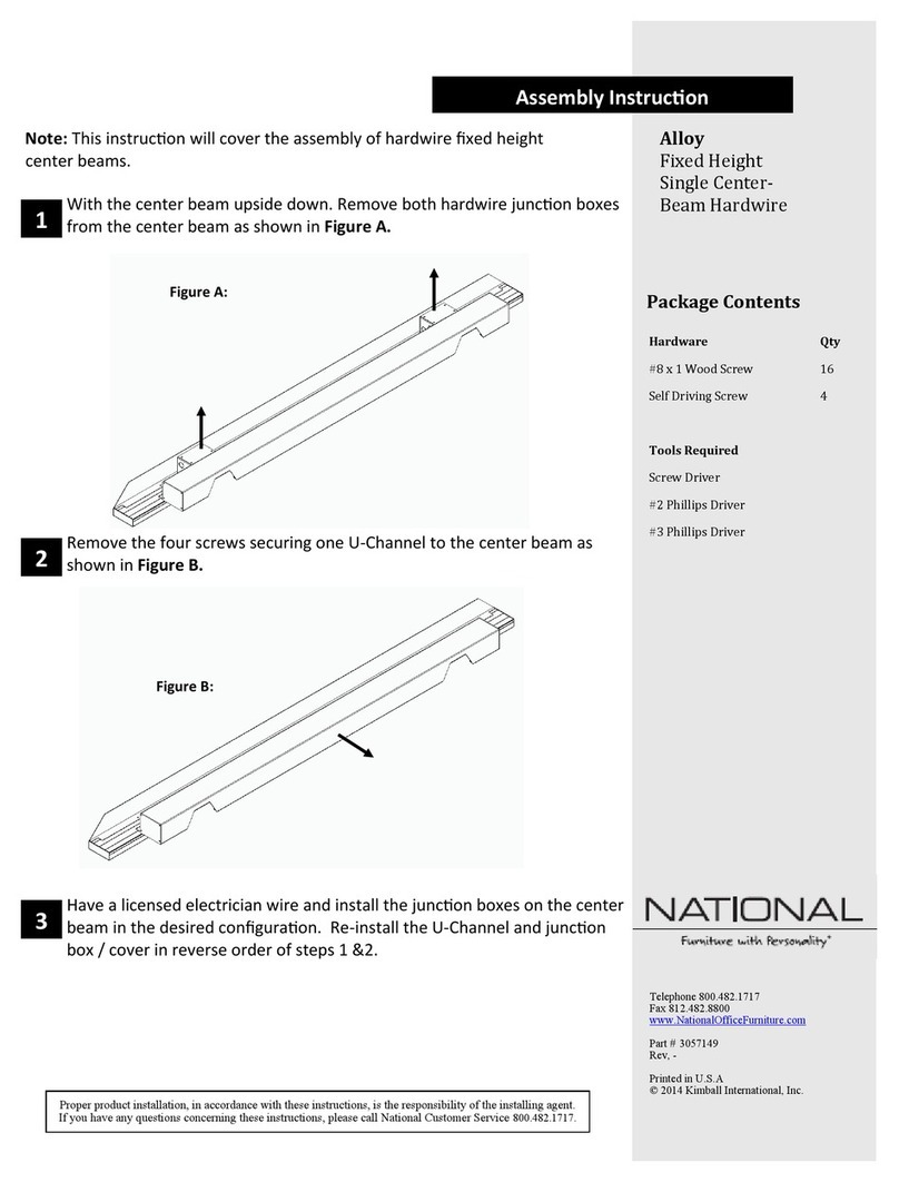
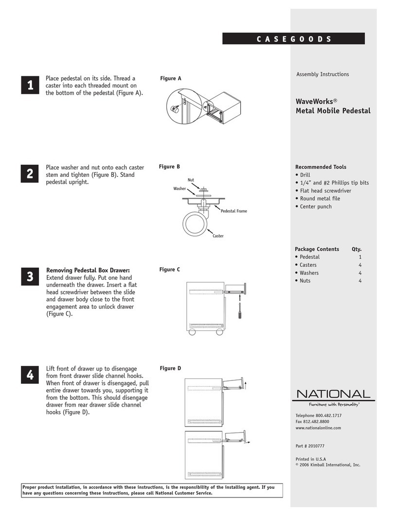
National Alloy User manual

National

National Alloy User manual

National Alloy User manual

National

National Alloy User manual

National LOCHLYN CORNICE TOP User manual

National

National LOCHLYN CORNICE TOP User manual

National Vora User manual

National

National Vora User manual

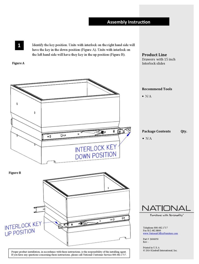
National Drawers with 15 inch Interlock slides User manual

National

National Drawers with 15 inch Interlock slides User manual

National Alloy User manual

National

National Alloy User manual

National Alloy User manual

National

National Alloy User manual

National Confide Chair Ganging User manual

National

National Confide Chair Ganging User manual

National Captivate Series User manual

National

National Captivate Series User manual

National Maneuver Educational Desk Series User manual

National

National Maneuver Educational Desk Series User manual

National Alloy User manual

National

National Alloy User manual

National Alloy User manual

National

National Alloy User manual

National Vora User manual

National

National Vora User manual

National WaveWorks User manual

National

National WaveWorks User manual

National Fringe User manual

National

National Fringe User manual

National TESSERA HGT. ADJ. DESK User manual

National

National TESSERA HGT. ADJ. DESK User manual

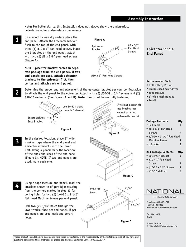
National Epicenter Single End Panel User manual

National

National Epicenter Single End Panel User manual

National Alloy User manual

National

National Alloy User manual

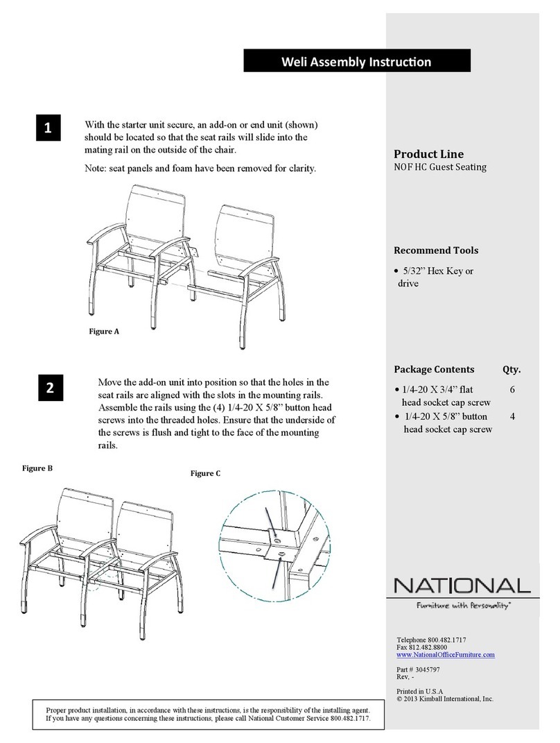
National NOF HC Guest Seating User manual

National

National NOF HC Guest Seating User manual

National Alloy User manual

National

National Alloy User manual

National LOCHLYN User manual

National

National LOCHLYN User manual

National Fierce Task Chair User manual

National

National Fierce Task Chair User manual

National Barrington User manual

National

National Barrington User manual

National Eloquence Series Ganging Center andCorner... User manual
National

National Eloquence Series Ganging Center andCorner... User manual

Popular Indoor Furnishing manuals by other brands

Regency LWMS3015 Assembly instructions

Regency

Regency LWMS3015 Assembly instructions

Furniture of America CM7751C Assembly instructions

Furniture of America

Furniture of America CM7751C Assembly instructions

Safavieh Furniture Estella CNS5731 manual

Safavieh Furniture

Safavieh Furniture Estella CNS5731 manual

PLACES OF STYLE Ovalfuss Assembly instruction

PLACES OF STYLE

PLACES OF STYLE Ovalfuss Assembly instruction

Trasman 1138 Bo1 Assembly manual

Trasman

Trasman 1138 Bo1 Assembly manual

Costway JV10856 manual

Costway

Costway JV10856 manual

moss DESIGN Caisson Credenza Assembly instructions

moss DESIGN

moss DESIGN Caisson Credenza Assembly instructions

Aquaglide FULL DECK 15.0 owner's manual

Aquaglide

Aquaglide FULL DECK 15.0 owner's manual

AREBOS AR-HE-SW30 user manual

AREBOS

AREBOS AR-HE-SW30 user manual

Till-Hilft Fulda 87005.330 Assembly instructions

Till-Hilft

Till-Hilft Fulda 87005.330 Assembly instructions

Twoey Outside 2010 quick start guide

Twoey Outside

Twoey Outside 2010 quick start guide

Hettich Easys 200 operating instructions

Hettich

Hettich Easys 200 operating instructions

The bedboss RELAX 404 Series owner's manual

The bedboss

The bedboss RELAX 404 Series owner's manual

Oeseder Möbelindustrie Bern 991 720 Assembly instructions

Oeseder Möbelindustrie

Oeseder Möbelindustrie Bern 991 720 Assembly instructions

Costway HW68469 user manual

Costway

Costway HW68469 user manual

Next ALIX A27743 Assembly instructions

Next

Next ALIX A27743 Assembly instructions

BROSA Hans Assembly guide

BROSA

BROSA Hans Assembly guide

Prodigg MINIKA PBA015T-FUR installation manual

Prodigg

Prodigg MINIKA PBA015T-FUR installation manual

manuals.online logo
manuals.online logoBrands
  • About & Mission
  • Contact us
  • Privacy Policy
  • Terms and Conditions

Copyright 2025 Manuals.Online. All Rights Reserved.