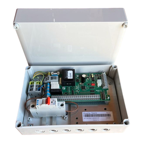
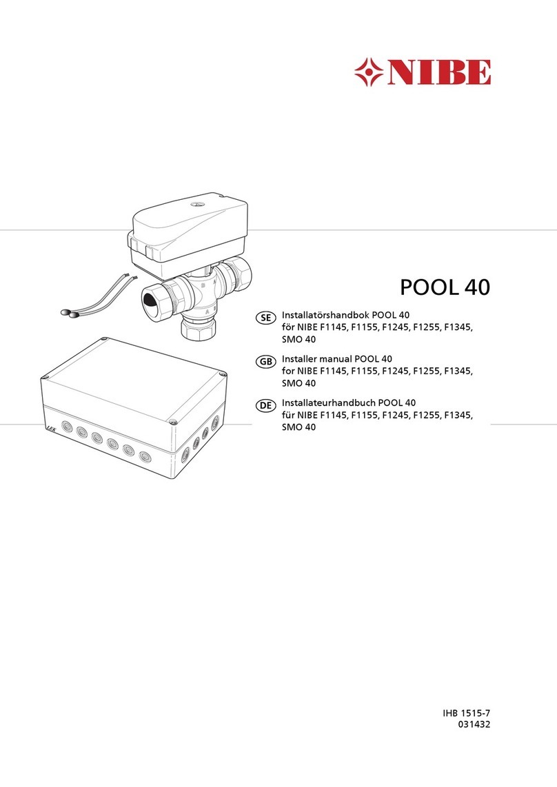
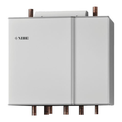
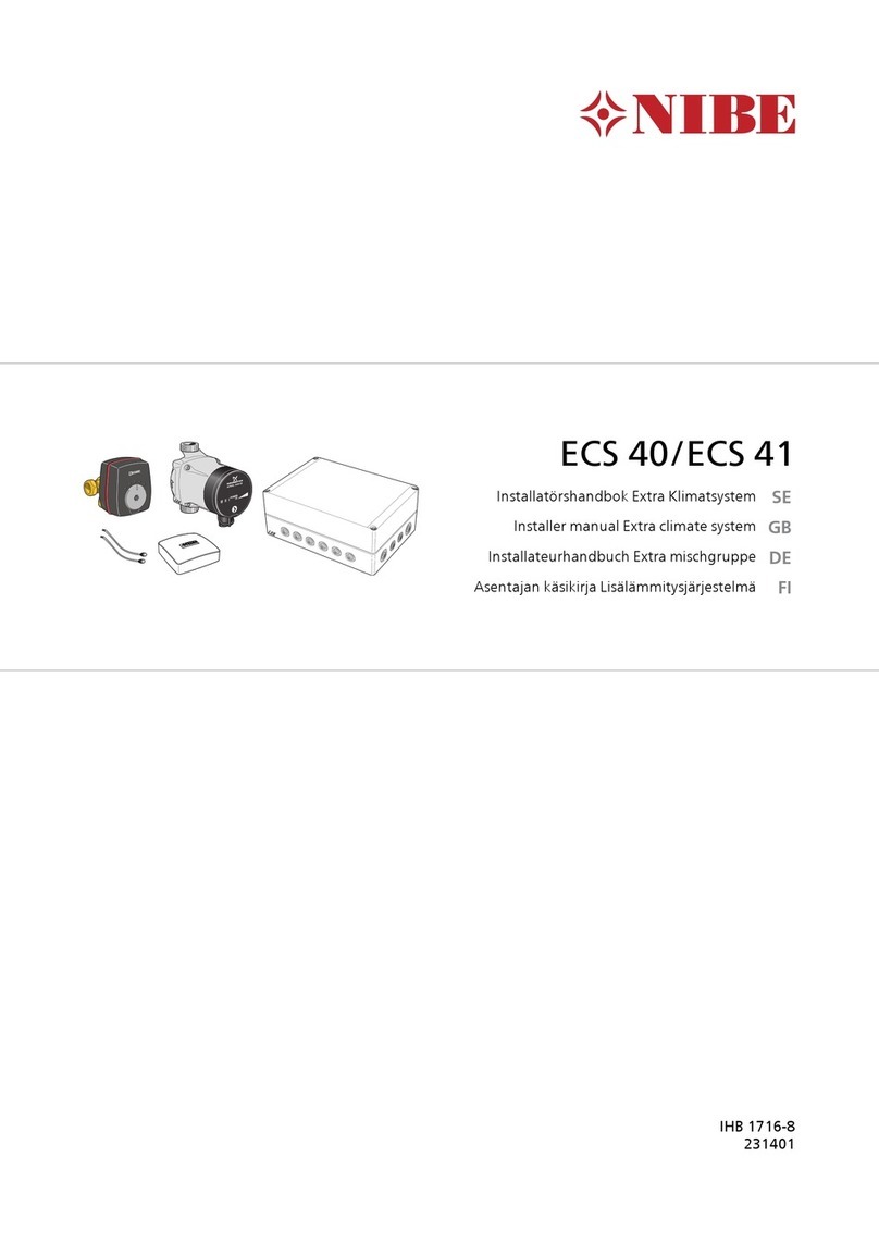
Nibe HPAC 42 User guide

LEK
HPAC 42
Installatörshandbok, HPAC 42 och F1345
SE
Installer manual, HPAC 42 and F1345
GB
Installateurhandbuch, HPAC 42 und F1345
DE
Manual de instalación, HPAC 42 y F1345
ES
IHB 1303-3
231159


Allmänt
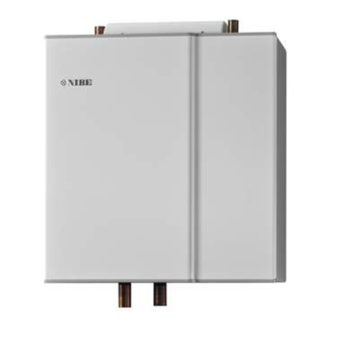
Tillbehöret HPAC 42 är en klimatväxlingsmodul som ska
ingå i ett system med värmepumpen NIBE F1345. NIBE
F1345 har inbyggt styrsystem för styrning av värme/kyla,
inbyggda cirkulationspumpar och ansluts via HPAC
42-modulen till yttre kollektor och husets klimatsystem
för värme och kyla.
Värmeväxlingen från värmekällan (berg, mark eller sjö)
sker via ett slutet köldbärarsystem där vatten blandat med
frysskyddsmedel cirkulerar till värmepumpen.
Även grundvatten kan användas som värmekälla. Men
det kräver en mellanliggande värmeväxlare mellan HPAC
42 och grundvattnet.
Innehåll
Väggfäste1st
Låsbleck1st
Kit för tillbehörskort1st
Rak koppling8st
Isoleringsrör, 45 mm6st
Isoleringsrör, 125 mm2st
Transport och förvaring
HPAC 42 ska transporteras och förvaras liggande samt
torrt.
;/;/
;/;/ ;/;/;/;/
3
Svenska, Installatörshandbok - HPAC 42
SE

Montering
Montera HPAC 42 med hjälp av den medlevererade
upphängningskonsolen, vilken först skruvas upp enligt
bild nedan.
Därefter hängs HPAC 42 på konsolen. HPAC 42 är nu till
viss del skjutbar i sidled, vilket underlättar rörinstallation.
OBS!
Montera bifogat låsbleck som tippskydd på valfri
plats nedtill på baksidan av HPAC 42 för ytterli-
gare fixering.
Installationskontroll
Enligt gällande regler skall värme-/kylanläggningen under-
gå installationskontroll innan den tas i bruk. Kontrollen
får endast utföras av person som har kompetens för
uppgiften och skall dokumenteras.
Ovanstående gäller slutna värme-/kylanläggningar. Utbyte
av värmepump eller HPAC-modul får ej ske utan förnyad
kontroll.
Styrning
Reglering av kyltillförsel till huset sker enligt inställningar
för framledningstemperatur i meny 1.9.5.
Vid stort kylbehov då passiv kyla inte är tillräcklig kopplas
aktiv kyla in vid inställt gradminutervärde.
När kylbehovet har upphört och värmepumpen ska återgå
till värmedrift eller tvärt om kan det ske tidigast efter 2
timmar (inställbart i meny 1.9.5).
Passiv kyla
Vid behov av passiv kyla startar cirkulationspumparna i
värmepumpen som cirkulerar vätska från mark-/bergkol-
lektorn in i husets klimatsystem och kyler huset. Kylan
tas från mark-/bergkollektorn.
Aktiv kyla
Vid aktiv kyla startar kompressorn i värmepumpen och
den producerade kylan cirkulerar till husets klimatsystem
och värmen cirkulerar ut till mark-/bergkollektorn.
4
SE

Växelventiler
Ventillägen
Värme-/kylläge styrs av 4 stycken växelventiler som beroende på utetemperaturen och behov växlar mellan olika lägen.
FLOWCONTROL FLOWCONTROL FLOWCONTROL FLOWCONTROL
41 41 41 41
)¸QVWUHQD S§ YHQWLOHUQD
NDQ YLVD EO§WW HOOHU U¸WW
EHURHQGH S§ RP )
J¸U Y¦UPH HOOHU N\OD
QN16QN14QN15QN13
röttröttröttröttVärme
blåttblåttröttröttPassiv kyla
blåttblåttblåttblåttAktiv kyla
Ovanstående gäller spänningssatt anläggning.
Pilen markerar i vilket läge ventilen står.
Ventilkontroll
FLOWCONTROL
Om ventilmotorerna har lossats och ventilerna har kommit
ur läge, justera ventilernas läge med exempelvis en skift-
nyckel för att få rätt ventilinställning.
Justera ventilerna enligt "värme" i tidigare tabell och
montera ventilmotorerna strömlösa, ställda i grundläge
(ström på, styrström av) och ena fönstret på motorn visar
rött.
Vid ingående styrsignal roterar ventilerna 90°.
TÄNK PÅ!
Vid ändring av värme-/kylläge föreligger en för-
dröjning på ca 60 sek innan ändringen av venti-
lernas läge äger rum.
5
SE

Kylmodulens konstruktion
41
41
41
;/ ;/
;/
;/;/
;/
41
;/;/8%
;
Växelventil 1, aktiv kylaQN13
Växelventil 2, passiv kylaQN14
Växelventil 3, aktiv kylaQN15
Växelventil 4, passiv kylaQN16
Kabelgenomföring, matning och signalUB1
Anslutningsplint, matning och signalX9
Värmebärare framXL1
Värmebärare returXL2
Köldbärare inXL6
Köldbärare utXL7
Dockning in (VB från värmepump)XL8
Dockning ut (VB till värmepump)XL9
Dockning in (KB från värmepump)XL16
Dockning ut (KB till värmepump)XL17
LEK
AA5-X4
AA5-S2
AA5-X2 AA5-X9 X1
FA1
AA5-F1AA5
Elkomponenter
Automatsäkring, 10AFA1
Anslutningsplint, spänningsmatningX1
TillbehörskortAA5
Anslutningsplint, givare och extern blocke-
ring
AA5-X2
Anslutningsplint, kommunikationAA5-X4
Anslutningsplint, cirkulationspump, shunt
och hjälprelä
AA5-X9
DIP-switchAA5-S2
Finsäkring, T4AH250VAA5-F1
Beteckningar i komponentplacering enligt standard IEC
81346-1 och 81346-2.
6
SE

Röranslutning
Allmänt
Rörinstallationen skall utföras enligt gällande regler. HPAC
42 kan endast arbeta upp till en returtemperatur av ca
50 °C och en utgående temperatur från värmepumpen
av ca 65 °C. Då värmepumpen inte är utrustad med av-
stängningsventiler måste sådana monteras utanför värme-
pumpen för att underlätta eventuell framtida service.
Vätskan i husets distributionssystem är densamma som i
mark-/bergkollektorn, om ingen avskiljande värmeväxlare
är inkopplad.
Rörinkoppling, husets klimatsystem
Anslut värmepumpen till HPAC 42 och eventuell varmvat-
tenberedning.
Rörinkoppling sker i botten och på toppen av HPAC 42.
Montera erforderlig säkerhetsutrustning, avstängnings-
ventiler (monteras så nära kylmodulen som möjligt), samt
smutsfilter (levereras med värmepumpen) så att även
HPAC 42 skyddas.
Om HPAC 42 ansluts till system med termostater i alla
konvektorer skall flöde garanteras antingen genom att
montera en överströmningsventil eller att demontera ett
antal termostater.
Rörinkoppling, kollektorsida
Kollektorslangens längd varierar beroende på
berg/markförhållanden och på klimatsystem.
Se till att kollektorslangen är konstant stigande mot vär-
mepumpen för att undvika luftfickor. Om det inte är
möjligt ska högpunkterna förses med avluftningsmöjlig-
heter.
Klimatsystemet skall förses med två tryckexpansionskärl.
Kondensisolera systemets samtliga rör utom rören till
varmvattenberedaren.
Då temperaturen på köldbärarsystemet kan understiga
0 °C måste detta frysskyddas genom inblandning av
propylenglykol (OBS! Ej etanol). Blandningsförhållandet
skall vara ca 25 % propylenglykol och resterande del
vatten. Som riktvärde för volymberäkning används 1 liter
färdigblandad köldbärarvätska per meter kollektorslang,
(gäller vid PEM-slang 40 x 2,4 PN 6,3).
Anläggningen ska märkas med det frysskyddsmedel som
används.
Montera avstängningsventiler så nära värmepumpen som
möjligt. Montera smutsfilter på inkommande ledning.
Vid anslutning till öppet grundvattensystem ska, p.g.a.
smuts och frysrisk i förångaren, en mellanliggande frys-
skyddad krets anordnas. Detta kräver en extra värmeväx-
lare. Dessutom skall grundvattenflödet vara tillräckligt
stort med hänsyn till alla komponenter.
OBS!
Denna systemlösning innebär att köldbäraren
kommer att cirkulera även genom värmesyste-
met.
Kontrollera att alla ingående komponenter är
konstruerade för aktuell köldbärare.
Tryckexpansionskärl
Köldbärarkretsen ska förses med tryckexpansionskärl (av
membrantyp). Eventuellt befintligt nivåkärl byts ut.
Tryckexpansionskärlet bör dimensioneras enligt diagram,
för att undvika driftstörningar. Tryckexpansionskärlet
täcker temperaturområdet från -10 °C till +20 °C vid
förtrycket 0,5 bar och säkerhetsventilens öppningstryck
3 bar. Köldbärarsidan skall normalt trycksättas till mellan
1,0 och 1,5 bar.
0
0100 200 300
10
20
30
40
50
400 500 600 700 800 900 1000
7U\FNH[SDQVLRQVN¦UO
.¸OGE¦UDUYRO\P
Kondensisolering
För att undvika kondensbildning måste rörledningar och
övriga kalla ytor isoleras med diffusionstätt material.
Då systemet kan köras med låga temperaturer måste en
eventuell fläktkonvektor vara utrustad med droppskål
och avloppsanslutning.
7
SE

Principschema
Förklaring
Värmepumpsystem (Master)EB100
Temperaturgivare, uteBT1
Temperaturgivare, varmvattenladdningBT6
Temperaturgivare, värmebärare fram, ExternBT25
Temperaturgivare, värmebärare retur, ExternBT71
Värmepump, F1345EB100
Kylmodul AEP14
Kylmodul BEP15
Säkerhetsventil, köldbärarsidaFL11 - FL12
Säkerhetsventil, värmebärarsidaFL13 - FL14
SmutsfilterHQ12 - HQ15
Avstängningsventil, köldbärarsidaQM50 - QM53
Avstängningsventil, värmebärarsidaQM54 - QM57
Växelventil, värme/varmvattenQN10
BackventilRM10 - RM13
HPAC 42EQ1
TillbehörskortAA5
Växelventil, kyla/värmeQN13 - QN16
Övrigt
Manometer, köldbärarsidaBP6
Ackumulatortank med varmvattenslingaCP10, CP11
Utjämningskärl (UKV)CP20
Expansionskärl slutet, värmebärarsidaCM1
Expansionskärl slutet, köldbärarsidaCM3
Kollektor, köldbärarsidaEP12
Säkerhetsventil, värmebärarsidaFL2
Säkerhetsventil, köldbärareFL3
Cirkulationspump, värmebärare externGP10
Avluftningsventil, köldbärarsidaQM21
Avstängningsventil, köldbärare framQM33
Avstängningsventil, köldbärare returQM34
TrimventilRN60 - RN63
Anslutning, påfyllning köldbärareXL27 - XL28
Beteckningar enligt standard IEC 81346-1 och 81346-2.
Principschema F1345 med HPAC 42
-EB100-BT71
-EP12
-EB100-BT1
-EB100-BT25
-EQ1
-CM3
P
-BP6 -QM21 -FL3
-XL28-XL27
-QM33
-QM34
-QN13 -QN15 -QN14 -QN16
-HQ15
-HQ14
-RM12
-RM13
-QM54
-FL12
-QM55
-QM56
-QM57
-FL13
-HQ13
-RM11
-HQ12
-RM10-QM50
-QM51
-FL10
-QM52
-QM53
-FL11
-EB100
-EP15
-EP14
-EB100
-EB100
-BT6
-CP10
-CM1
-FL2
-RN63
-RN62
-CP11
-RN60
-RN61
-EB100-QN10
-CP20
-GP13
-EQ1-AA5
8
SE

Elinkoppling
OBS!
All elektrisk inkoppling skall ske av behörig
elektriker.
Elektrisk installation och ledningsdragning skall
utföras enligt gällande bestämmelser.
Värmepumpen ska vara spänningslös vid instal-
lation av HPAC 42.
Elschema finns i slutet av denna installatörshandbok.
Anslutning av kommunikation
Detta tillbehör innehåller ett tillbehörskort (AA5) som ska
anslutas direkt till värmepumpen på plint X6 i F1345.
Om flera tillbehör ska anslutas eller redan finns installera-
de måste nedanstående instruktion följas.
Det första tillbehörskortet ska anslutas direkt på plint X6
i F1345. De efterföljande korten ansluts i serie med före-
gående kort.
Använd kabeltyp LiYY, EKKX eller likvärdig.
1
2
3
4
5
6
7
8
AA5-X4
A
B
GND
A
B
GND
A
B
GND
A
B
GND
1
2
3
4
5
6
7
8
AA5-X4
X6
1234
A
B
GND
7LOOEHK¸UVNRUW
7LOOEHK¸UVNRUW
ON
12345678
-X9
-X2
24 20212223 1516171819 1011121314 567891
1
N
L
PE
PE
1
2
3
4
5
6
7
8
2
3
4
5
6
7
8
9
234
-X8
-X4
-X10
-X1
$$;
ON
12345678
-X9
-X2
24 20212223 1516171819 1011121314 567891
1
N
L
PE
PE
1
2
3
4
5
6
7
8
2
3
4
5
6
7
8
9
234
-X8
-X4
-X10
-X1
$$;
(%
LEK
)
;
Anslutning av matning
Anslut spänningsmatningen till plint X1 enligt bild.
3
2
1N
230V 50Hz-X1
L
PE
$SSDUDWO§GD ([WHUQW
9
SE

ON
12345678
-X9
-X2
24 20212223 1516171819 1011121314 567891
1
N
L
PE
PE
1
2
3
4
5
6
7
8
2
3
4
5
6
7
8
9
234
-X8
-X4
-X10
-X1
$$; $$;
$$;
OBS!
All elektrisk inkoppling skall ske av behörig
elektriker.
Elektrisk installation och ledningsdragning skall
utföras enligt gällande bestämmelser.
F1345 ska vara spänningslös vid installation av
HPAC 42.
Anslutning av extern blockering
Använd kabeltyp LiYY, EKKX eller likvärdig.
Extern blockering, passiv kyla (valfritt)
En kontakt (NO) kan anslutas till AA5-X2:23-24 för att
kunna blockera passiv kyla. När kontakten sluts blockeras
passiv kyla.
Extern blockering, aktiv kyla (valfritt)
En kontakt (NO) kan anslutas till AA5-X2:21-22 för att
kunna blockera aktiv kyla. När kontakten sluts blockeras
aktiv kyla.
24 20212223 1516171819 1314
$$;
([WHUQW
$SSDUDWO§GD
([WHUQ EORFNHULQJ
$ %
$ 3DVVLY N\OD
% $NWLY N\OD
TÄNK PÅ!
Reläutgångarna på tillbehörskortet får max be-
lastas med 2 A (230 V) totalt.
Anslutning av HPAC 42 till tillbehörskort
(AA5)
Anslut anslutningsplint (X9) i HPAC 42 till tillbehörskort
(AA5) enligt följande. X9:L till AA5-X10:2 (230 V), X9:N
till AA5-X10:1 (N), X9:1 till AA5-X9:2 (manöver, ACX),
X9:2 till AA5-X9:2 (manöver, PCX) och jordstift (PE) till
X1:3 (PE).
1
2
1
2
3
4
5
6
7
8
9
3
2
1
NL12
PCX
ACX
230 V
N
PE
$$;
$$;
;
;
$SSDUDWO§GD +3$&
Anslutning av eventuell cirkulationspump
(GP13)
Anslut cirkulationspumpen (GP13) till AA5-X9:8 (230 V),
AA5-X9:7 (N) och X1:3 (PE).
1
2
3
4
5
6
7
8
9
L
N
PE
3
2
1
$SSDUDWO§GD ([WHUQW
*3
$$; ;
DIP-switch
DIP-switchen på tillbehörskortet ska ställas in enligt ne-
dan.
ON
12345678
ON
12345678
-X9
-X2
24 20212223 1516171819 1011121314 567891
1
N
L
PE
PE
1
2
3
4
5
6
7
8
2
3
4
5
6
7
8
9
234
-X8
-X4
-X10
-X1
$$6
10
SE

Reläutgång för kyllägesindikering
Möjlighet finns till extern kyllägesindikering genom relä-
funktion via ett potentialfritt växlande relä (max 2 A) på
kopplingsplint X5.
Ansluts kyllägesindikering till kopplingsplint X5 måste det
väljas i meny 5.4.
Programinställningar
Programinställningen av HPAC 42 kan göras via startgui-
den eller direkt i menysystemet i NIBE F1345.
TÄNK PÅ!
Se även Drifthandboken för F1345.
Startguiden
Startguiden visas vid första uppstart efter värmepumpsin-
stallationen, men finns även i meny 5.7.
Menysystemet
Om du inte gör alla inställningar via startguiden eller be-
höver ändra någon inställning kan du göra detta i meny-
systemet.
Meny 5.2.4 - tillbehör
Aktivering/avaktivering av tillbehör.
Välj: "passiv/aktiv kyla 2-rör".
Meny 1.1 - temperatur
Inställning av inomhustemperatur (kräver rumstempera-
turgivare).
Meny 1.9.5 - kylinställningar
Här kan du exempelvis göra följande inställningar:
႑Lägsta framledningstemperatur vid kyla.
႑Önskad framledningstemperatur vid utomhustempe-
raturen +20 och +40 °C.
႑Tid mellan kyla och värmedrift eller tvärt om.
႑Val om rumsgivare ska styra kylan.
႑Hur mycket rumstemperaturen får sjunka respektive
öka jämfört med önskad temperatur innan övergång
till värme respektive kyldrift (kräver rumsgivare).
႑Gradminutnivåer för kyla.
႑Diverse shuntinställningar.
Meny 5.6 - tvångsstyrning
Tvångsstyrning av de olika komponenterna i värmepum-
pen samt i de olika tillbehören som eventuellt är anslutna.
EQ1-AA5-K1: Signal till växelventilerna (QN13) och
(QN15).
EQ1-AA5-K2: Signal till växelventilerna (QN14) och
(QN16).
EQ1-AA5-K3: Ingen funktion.
EQ1-AA5-K4: Aktivering av cirkulationspump (GP13).
11
SE

Tekniska uppgifter
Mått
600
300
694 76,5
76,5
847
928
37,5
100 200 100
62,5
497
286,5
54,5
286,5
230,5
150
12
SE

Tekniska data
230V 50 HzSpänning
690(mm)Höjd
600(mm)Bredd
495(mm)Djup
20-40(kW)Avsedd för värmepumpar
Cu42 (1,5”)(mm)Röranslutning
45(kg)Vikt
13
SE

General
The accessory HPAC 42 is a climate exchange module
that is to be included in a system with heat pump NIBE
F1345. NIBE F1345 has an integrated control system to
control heating/cooling, integrated circulation pumps and
is connected via the HPAC 42 module to the external
collector and the building's climate system for heating
and cooling.
The heat exchange from the heat source (rock, surface
soil or lake) takes place via a closed brine system in which
water mixed with antifreeze circulates to the heat pump.
Ground water can also be used as heat source. However,
an intermediate heat exchanger is required between
HPAC 42 and the ground water.
Contents
Wall bracket1x
Securing plate1x
Kit for accessory card1x
Straight connection8x
Insulation pipe, 45 mm6x
Insulation pipe, 125 mm2x
Transport and storage
HPAC 42 must be transported and stored horizontally
and dry.
;/;/
;/;/ ;/;/;/;/
14
English, Installer manual - HPAC 42
GB

Mounting
Install HPAC 42 using the supplied mounting brackets,
which should be screwed into place first, see the follow-
ing illustration.
Then mount HPAC 42 on the brackets. HPAC 42 can now
be easily moved sideways, which facilitates pipe installa-
tion.
NOTE
Install the accompanying securing plate any-
where at the bottom rear of HPAC 42 for further
fastening.
Inspection of the installation
In accordance with current norms, the heating/cooling
installation must undergo an installation check before
being used. The inspection must be carried out by a
suitably qualified person and should be documented.
The above applies to closed heating/cooling installations.
If the heat pump or the HPAC module are replaced the
installation must be inspected again.
Control
The cooling supply to the building is controlled by the
flow temperature settings in menu 1.9.5.
When the cooling requirement is large and passive cooling
is not sufficient, active cooling is engaged at the set de-
gree minute value.
When the demand for cooling has stopped and the heat
pump is to return to heating mode or vice versa, there is
at least a 2 hour delay (adjustable in menu 1.9.5) before
switching.
Passive cooling
When passive cooling is required, the circulation pumps
in the heat pump start, to circulate fluid from the surface
soil/rock collector through the building’s distribution sys-
tem and cool the building. Cooling comes from the sur-
face soil/rock collector.
Active cooling.
With active cooling the compressor in the heat pump
starts and the resulting cold medium circulates to the
building’s distribution system and the heat circulates out
to the surface soil/rock collector.
15
GB

Reversing valves
Valve positions
The heating/cooling modes are controlled by 4 reversing valves, which, depending on the outdoor temperature, switch
between the different modes.
FLOWCONTROL FLOWCONTROL FLOWCONTROL FLOWCONTROL
41 41 41 41
7KH ZLQGRZV RQ WKH
YDOYHV FDQ VKRZ EOXH RU
UHG GHSHQGLQJ RQ ZKHWKHU
) SURYLGHV KHDWLQJ RU
FRROLQJ
QN16QN14QN15QN13
redredredredHeating
blueblueredredPassive cooling
blueblueblueblueActive cooling.
The above applies to powered systems.
The arrow indicates in which position the valve is set.
Valve position checks
FLOWCONTROL
If the valve motors have become loose and the valves
have come out of position, adjust the position of the
valves using a wrench to obtain the right valve setting.
Adjust the valves according to the previous table "heat-
ing" and install with the valve motors unpowered, set to
default position (current on, control current off) and one
window on the motor displaying red.
At input control signal the valves rotate 90°.
Caution
When changing the heating/cooling mode, there
is a delay of approximately 60 seconds before
the valves change their positions.
16
GB

The cooling module's design
41
41
41
;/ ;/
;/
;/;/
;/
41
;/;/8%
;
Reversing valve 1, active coolingQN13
Reversing valve 2, passive coolingQN14
Reversing valve 3, active coolingQN15
Reversing valve 4, passive coolingQN16
Cable grommet, supply and signalUB1
Terminal block, supply and signalX9
Heating medium supplyXL1
Heating medium returnXL2
Brine inXL6
Brine outXL7
Docking in (HM from heat pump)XL8
Docking out (HM to heat pump)XL9
Docking in (Brine from heat pump)XL16
Docking out (Brine to heat pump)XL17
LEK
AA5-X4
AA5-S2
AA5-X2 AA5-X9 X1
FA1
AA5-F1AA5
Electrical components
Miniature circuit-breaker. 10AFA1
Terminal block, power supplyX1
Accessory cardAA5
Terminal block, sensors and external bloc-
king
AA5-X2
Terminal block, communicationAA5-X4
Terminal block, circulation pump, mixing
valve and auxiliary relay
AA5-X9
DIP switchAA5-S2
Fine wire fuse, T4AH250VAA5-F1
Designations in component locations according to
standard IEC 81346-1 and 81346-2.
17
GB

Pipe connections
General
Pipe installation must be carried out in accordance with
current norms and directives. HPAC 42 can only operate
up to a return temperature of about 50 °C and an outgo-
ing temperature of about 65 °C from the heat pump.
When the heat pump is not equipped with shut off valves;
these must be installed outside the heat pump to facilitate
any future servicing.
The fluid in the building's distribution system is the same
as in the surface soil/rock collector, if no other heat ex-
changer is connected.
Pipe connection, the building’s climate sy-
stem
Connect the heat pump to HPAC 42 and, where applic-
able, hot water heating.
Pipe connections are made at the bottom and top of
HPAC 42. All required safety devices, shut-off valves (in-
stalled as close to the cooling module as possible), and
particle filter (supplied with the heat pump) are to be fit-
ted in such a way that HPAC 42 is also protected.
If HPAC 42 is connected to a system with thermostats on
all convectors, a bypass valve must be fitted, or a thermo-
stat must be removed to ensure sufficient flow.
Pipe connection, collector side
The length of the collector hose varies depending on the
rock /surface soil conditions and on the climate system.
Ensure the collector hose rises constantly towards the
heat pump to avoid air pockets. If this is not possible,
airvents should be used.
The climate system must be supplied with two pressure
expansion vessels.
All the system's pipes must be condensation insulated
except the pipes to the water heater.
If the temperature of the brine system can fall below 0
°C this must be protected against freezing through the
mixture of propylene glycol (NOTE! Not ethanol). The
mixing ratio should be approximately 25 % propylene
glycol and the remainder water. As a guideline for the
volume calculation, use 1 litre of ready mixed brine per
meter of collector hose, (for 40 x 2.4 PN 6.3 PEM hose).
The installation should be marked with the antifreeze
used.
Install shut off valves as close to the heat pump as pos-
sible. Fit a particle filter to the incoming pipe.
In the case of connection to an open groundwater system,
an intermediate frost-protected circuit must be provided,
because of the risk of dirt and freezing in the evaporator.
This requires an extra heat exchanger. In addition, the
ground water flow must be sufficiently large for all com-
ponents.
NOTE
This system solution means that the brine will
also circulate through the heating system.
Check that all component parts are designed
for the brine in question.
Expansion vessel
The brine circuit must be supplied with a pressure expan-
sion vessel (membrane type). If there is already a level
vessel installed this should be replaced.
The pressure expansion vessel should be dimensioned as
set out in the diagram, to prevent operating disturbances.
The pressure expansion vessel covers the temperature
range from -10 °C to +20 °C for the brine at a pre-pres-
sure of 0,5 bar and the safety valve's opening pressure
of 3 bar. The brine side must normally be pressurised to
at between 1,0 and 1,5 bar.
0
0100 200 300
10
20
30
40
50
400 500 600 700 800 900 1000
([SDQVLRQ YHVVHO
%ULQH YROXPH
Condensation insulation
Pipes and other cold surfaces must be insulated with dif-
fusion-proof material to prevent condensation.
Where the system may be operated at low temperatures,
any convection fan used must be fitted with a drip tray
and drain connection.
18
GB

Outline diagram
Explanation
Heat pump system (Master)EB100
Temperature sensor, outdoorBT1
Temperature sensor, hot water chargingBT6
Temperature sensor, heating medium flow,
External
BT25
Temperature sensor, heating medium return,
External
BT71
Heat pump, F1345EB100
Cooling module AEP14
Cooling module BEP15
Safety valve, collector sideFL11 - FL12
Safety valve, heating medium sideFL13 - FL14
Particle filterHQ12 - HQ15
Shut-off valve, brine sideQM50 - QM53
Shut-off valve, heating medium sideQM54 - QM57
Reversing valve, heating/hot waterQN10
Non-return valveRM10 - RM13
HPAC 42EQ1
Accessory cardAA5
Reversing valve, cooling/heatingQN13 - QN16
Miscellane-
ous
Manometer, brine sideBP6
Accumulator tank with hot water coilCP10, CP11
Buffer vessel (UKV)CP20
Expansion vessel, closed, heating medium
side
CM1
Expansion vessel, closed, brine sideCM3
Collector, brine sideEP12
Safety valve, heating medium sideFL2
Safety valve, brineFL3
Circulation pump, heating medium externalGP10
Venting valve, brine sideQM21
Shut off valve, brine flowQM33
Shut off valve, brine returnQM34
Trim valveRN60 - RN63
Connection, filling brineXL27 - XL28
Designations according to standards 81346-1 and 81346-
2.
Outline diagram F1345 with HPAC 42
-EB100-BT71
-EP12
-EB100-BT1
-EB100-BT25
-EQ1
-CM3
P
-BP6 -QM21 -FL3
-XL28-XL27
-QM33
-QM34
-QN13 -QN15 -QN14 -QN16
-HQ15
-HQ14
-RM12
-RM13
-QM54
-FL12
-QM55
-QM56
-QM57
-FL13
-HQ13
-RM11
-HQ12
-RM10-QM50
-QM51
-FL10
-QM52
-QM53
-FL11
-EB100
-EP15
-EP14
-EB100
-EB100
-BT6
-CP10
-CM1
-FL2
-RN63
-RN62
-CP11
-RN60
-RN61
-EB100-QN10
-CP20
-GP13
-EQ1-AA5
19
GB

Electrical connection
NOTE
All electrical connections must be carried out by
an authorised electrician.
Electrical installation and wiring must be carried
out in accordance with the stipulations in force.
The heat pump must not be powered when in-
stalling HPAC 42.
The electrical circuit diagram is at the end of this Installer
handbook.
Connecting communication
This accessory contains an accessory card (AA5) that must
be connected directly to the heat pump on terminal block
X6 in F1345.
If several accessories are to be connected or are already
installed, the following instructions must be followed.
The first accessory card must be connected directly to the
terminal block X6 in F1345. The following cards must be
connected in series with the previous card.
Use cable type LiYY, EKKX or similar.
1
2
3
4
5
6
7
8
AA5-X4
A
B
GND
A
B
GND
A
B
GND
A
B
GND
1
2
3
4
5
6
7
8
AA5-X4
X6
1234
A
B
GND
$FFHVVRU\ FDUG
$FFHVVRU\ FDUG
ON
12345678
-X9
-X2
24 20212223 1516171819 1011121314 567891
1
N
L
PE
PE
1
2
3
4
5
6
7
8
2
3
4
5
6
7
8
9
234
-X8
-X4
-X10
-X1
$$;
ON
12345678
-X9
-X2
24 20212223 1516171819 1011121314 567891
1
N
L
PE
PE
1
2
3
4
5
6
7
8
2
3
4
5
6
7
8
9
234
-X8
-X4
-X10
-X1
$$;
(%
LEK
)
;
Connecting the supply
Connect the power supply to terminal block X1 as illus-
trated.
3
2
1N
230V 50Hz-X1
L
PE
8QLW ER[ ([WHUQDO
20
GB
Table of contents
Languages:
Other Nibe Temperature Controllers manuals
Popular Temperature Controllers manuals by other brands

DOTECH
DOTECH TX3 Series operating instructions

Ropex
Ropex RESISTRON RES-5027 operating instructions

Gemo
Gemo LT102HT quick start guide

Carbolite
Carbolite 201 operating instructions

REGLOPLAS
REGLOPLAS 300L operating instructions

Viessmann
Viessmann VITOSOLIC 100 Installation and service instructions for contractors