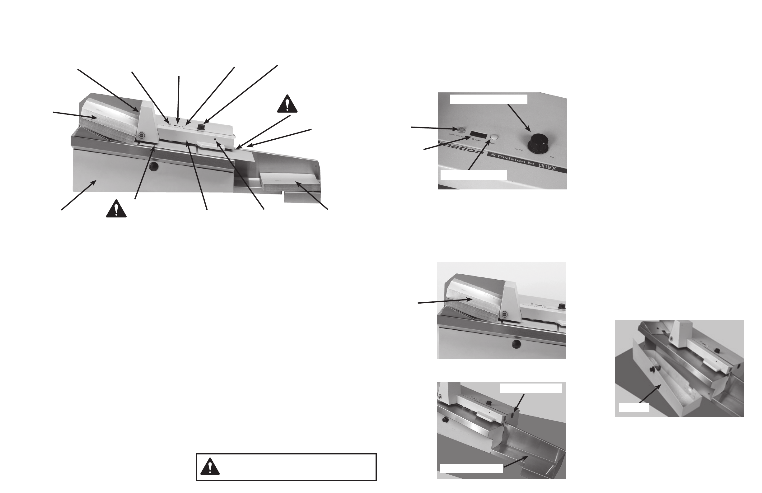
manuals.online logo
Brands
  1. Home
  2. •
  3. Brands
  4. •
  5. Opex
  6. •
  7. Postal Equipment
  8. •
  9. Opex Pitnew Bowes Omation 2100 Manual

Opex Pitnew Bowes Omation 2100 Manual

Opex Omation 2100
Letter Opener
Operator Guide
Cutter Adjustment
The 2100 will arrive with the cutter preset from the factory.
However, the cutter can be adjusted to accomodate differ-
ent mail thicknesses by turning the Cutter Adjustment Screw
(which can be accessed through the access hole- See pic
below). Turn off power to the 2100. Insert the supplied 5/32”
long-arm hex wrench through the small hole and engage the
Cutter Adjustment Screw. Turning the Cutter Adjustment Screw
clockwise will increase the depth of cut, turning the screw
counter-clockwise will decrease the depth of cut.
Upper Transport Cover Removal/Replacement
The Upper Transport Cover (See Pic Below) may be removed
to facilitate cleaning of the 2100. To remove the Upper Trans-
port Cover, turn the machine off. Grasp the right end of the
Upper Transport Cover, pull upwards and remove. Reverse the
procedure to re-install the Upper Transport Cover. The 2100
will not operate until the Upper Transport Cover is properly
installed.
Maintenance
Cleaning the 2100
Cleaning the 2100 should be performed daily after use.
1. Unplug the power cord.
2. Remove the Upper Transport Cover (See
previous column).
3. Remove and Empty the Chip Bin (See Chip
Bin Full information on previous page).
4. Vacuum loose paper chips from the machine.
5. Use a cloth moistened with liquid cleaner to
wipe down the exterior of the machine.
NOTE: Do not apply liquid cleaner directly to
the 2100.
6. Re-install Chip Bin and Upper Transport
Cover.
Speci cations
Length: 102cm
Depth: 39cm
Height: 36cm
Weight: 28Kg
Power: 220-240 VAC, 50Hz, 3 Amps.
Speed: 400 Envelopes per minute
Envelopes Supported: All Main Envelope Sizes
Thickness: Up to 5mm
Depth of Cut: 0.25-2.5mm
Noise Level: <80 dBA
Cutter Adjustment Screw
Upper Transport Cover
Adjusting the Separator Stones
The separator stones facilitate feeding and help to prevent
double-feeds. For most envelopes, set the stone pair .010 inch
above the top of feed belt level. You should be able to see light
between the stones and the belt. Set the stones slightly higher
for thick envelopes or slightly below the belt level for thin enve-
lopes.
1. Place yourself eye level with the belt and stones.
2. Find the access hole for adjusting screw in the centre
of the letter tray plate in the feed hopper (See pic in
next column).
3. Use a 5/32-inch hex key to adjust the separator
stones (See Pic Below).
Stone Adjustment Screw
It is certified that the system complies with all
applicable Directives of the European Union.
Envelope Feed
Hopper
LED Counter
Indicator Readout
Window
Chip Bin Full
Indicator Light
Counter Reset
Button
Cut/No Cut
Selector Knob
CAUTION!
Pinch Point
Power On/Off
Switch
Envelope
Catch Tray
Cutter Adjustment
Screw Access
Hole
Upper
Transport
Cover
Chip Bin
CAUTION!
Pinch Point
2100 Letter Opener
Identication
Safety
Follow the normal safety precautions for all office equipment:
• Use only Pitney Bowes approved supplies, in particular
aerosol dusters. Improper storage and use of aerosol
dusters or flammable aerosol dusters can cause an
explosive-like condition that could result in personal injury
and/or property damage. Never use aerosol dusters
labeled flammable and always read instructions and safety
precautions on the duster label.
• To obtain supplies, please contact our Supply Line™ to
place orders. Material Safety Data Sheets can be obtained
on the web or from our Supply Line™. Refer to the Contact
Information List for more information.
• Use the power cord supplied with the machine and plug
it into a properly grounded wall outlet located near the
machine and easily accessible. Failure to properly ground
the machine can result in severe personal injury and/or
fire.
• Avoid touching moving parts or materials while the
machine is in use. Keep hands, loose clothing, jewellery
and long hair away from all moving parts.
• Do not remove covers or defeat safety interlock switches.
Covers enclose hazardous parts that should only
be accessed by properly trained service personnel.
Immediately report to service any damaged or non-
functioning components that renders the unit unsafe.
• Place the unit in an accessible location to allow for proper
venting of the equipment and to facilitate servicing.
• The power cord wall plug is the primary means of
disconnecting the machine from the AC supply.
• Do not use an adapter plug on the line cord or wall outlet.
• Do not remove the ground pin from the line cord.
• Avoid using wall outlets that are controlled by wall
switches, or shared with other equipment.
• Do not route the power cord over sharp edges or trap
between furniture.
• Ensure there is no strain on the power cord and that it
does not become jammed between the equipment, walls
or furniture.
• Be certain the area in front of the wall receptacle into
which the machine is plugged is free from obstruction.
• Before clearing a stoppage, be sure machine mechanisms
come to a stop.
• When removing stalled material, avoid using too much
force to protect against minor personal injury and
damaging equipment.
• To prevent overheating, do not cover any vent openings.
• Operation of this equipment without periodic maintenance
will inhibit optimum operating performance and could
cause the equipment to malfunction. Contact your machine
supplier for required service schedule.
• Read all instructions before attempting to operate the
equipment.
• Use this equipment only for its intended purpose.
• Always follow the specific occupational safety and health
standards for your workplace.
WARNING: THIS EQUIPMENT MUST BE EARTHED
The socket outlet should be near to the equipment and
should be easily accessible.
Operation
Operating the 2100
1. Make sure the power cord is connected to the 2100
and the plug is securely connected to the power
receptacle.
2. Select either ‘No Cut’ or ‘Cut’ position on the Cut/No
Cut Selector Knob (See pic below) located on the
top of the 2100. See Cut/No Cut Function for more
information.
3. Reset Counter, if desired, by pressing the Counter
Reset Button (See Pic Above) next to the LED Count
Indicator Readout Window. See Counter Function
for more information.
4. Load mail (approximately 50 pieces) onto the Enve-
lope Feed Hopper (See Pic below). Be sure to justify
the side of the mail to be cut against the back of the
Feed Hopper.
5. To begin Operation turn the On/Off Power Switch
(See Pic below) to the On position.
LED Count
Indicator
Readout
Window
6. Once the Envelope Feed Hopper is empty, empty the
Envelope Catch Tray (See Pic on previous column).
7. To continue processing, repeat the above steps.
Cut/No Cut Function
The 2100 is capable of counting individual pieces of mail with
or without opening the envelope. This function can be selected
by turning the Cut/No Cut Knob to the desired selection posi-
tion.
NOTE: Adjusting the cutter to the maximum depth of cut can
defeat the ‘No Cut’ option.
Counter Function
The 2100 Letter Opener counts individual pieces of mail
processed in either the ‘No Cut’ or ‘Cut’ mode. Even if power is
lost to the machine or the machine is turned off, the 2100 will
maintain the count total. Once the count is reset the previous
count is lost. The condition of the mail and the cleanliness of
the machine can effect the accuracy of the count.
Removal/ Replacement and Adjustments
Chip Bin Full
The Chip Bin Full Indicator Light (See pic below) indicates that
the Chip Bin is full and needs to be emptied. Removal and
Replacement of the Chip Bin resets the indicator. The Chip Bin
which is located under the cutting deck can be accessed by
pressing the black pop-out button, located in the centre of the
bin and rotating it in either direction, while pulling towards the
operator. the bin can be completely removed for easy disposal.
To replace the Chip Bin, slide the bin forward into the machine
until completely in place. Press the button in, to lock the bin
in place. the machine will not run unless the bin is properly
locked into place.
NOTE: Be sure to clean the cavity in which the Chip Bin
resides. Build up of chips behind the Chip Bin can prevent the
bin locking into place and the machine from working.
Cut/No Cut Selector Knob
Counter Reset Button
Feed
Hopper
On/Off Power Switch
Envelope Catch Tray
Chip Bin Full
Indicator
Light
Chip Bin
Stone
Adjustment
Screw
Access Hole

Other Opex Postal Equipment manuals

Opex Model 72 User manual

Opex

Opex Model 72 User manual

Opex Omation Envelopener 210 Series User manual

Opex

Opex Omation Envelopener 210 Series User manual

Opex Envelopener Omation 2100 Specifications

Opex

Opex Envelopener Omation 2100 Specifications

Opex Omation 306 User manual

Opex

Opex Omation 306 User manual

Opex Sure Sort User manual

Opex

Opex Sure Sort User manual

Opex Omation Envelopener 210 Series User manual

Opex

Opex Omation Envelopener 210 Series User manual

Opex Falcon+ User manual

Opex

Opex Falcon+ User manual

Opex Omation 206 Manual

Opex

Opex Omation 206 Manual

Opex Omation 206 Manual

Opex

Opex Omation 206 Manual

Opex Envelopener Omation 306 User manual

Opex

Opex Envelopener Omation 306 User manual

Opex Sure Sort User manual

Opex

Opex Sure Sort User manual

Opex 51 User manual

Opex

Opex 51 User manual

Opex Sure Sort User manual

Opex

Opex Sure Sort User manual

Opex MPS 40 User manual

Opex

Opex MPS 40 User manual

Opex AS7200 User manual

Opex

Opex AS7200 User manual

Opex Perfect Pick User manual

Opex

Opex Perfect Pick User manual

Opex Perfect Pick Cortex User manual

Opex

Opex Perfect Pick Cortex User manual

Opex Eagle Remittance Processor User manual

Opex

Opex Eagle Remittance Processor User manual

Opex Omation Envelopener 210 Series User manual

Opex

Opex Omation Envelopener 210 Series User manual

Popular Postal Equipment manuals by other brands

Salsbury Industries 4325 installation instructions

Salsbury Industries

Salsbury Industries 4325 installation instructions

Neopost IN-360 Self-installation guide

Neopost

Neopost IN-360 Self-installation guide

Pitney Bowes SendPro HVF1 user guide

Pitney Bowes

Pitney Bowes SendPro HVF1 user guide

Zippity MAJESTIC Assembly instructions

Zippity

Zippity MAJESTIC Assembly instructions

Neopost IJ35 Getting started

Neopost

Neopost IJ35 Getting started

Frama Fs 3 Series Quick installation guide

Frama

Frama Fs 3 Series Quick installation guide

quadient IN-600 user guide

quadient

quadient IN-600 user guide

Neopost ij25 user guide

Neopost

Neopost ij25 user guide

SSS Siedle BE 611-3/1-0 Product information

SSS Siedle

SSS Siedle BE 611-3/1-0 Product information

Ricoh mSorter OCR user manual

Ricoh

Ricoh mSorter OCR user manual

PAKETSAFE Paketsafe Plus Loxone Installation

PAKETSAFE

PAKETSAFE Paketsafe Plus Loxone Installation

Mayne Woodhaven Sign Post Assembly instructions

Mayne

Mayne Woodhaven Sign Post Assembly instructions

quadient IS-280 Guide

quadient

quadient IS-280 Guide

Pitney Bowes PCN 9H00 Operator's guide

Pitney Bowes

Pitney Bowes PCN 9H00 Operator's guide

Neopost IJ 70 manual

Neopost

Neopost IJ 70 manual

Gibraltar Industries AF FLORENCE ExpressLocker Maintenance & Troubleshooting guide

Gibraltar Industries

Gibraltar Industries AF FLORENCE ExpressLocker Maintenance & Troubleshooting guide

FP Mailing Solutions MyMail Operator's manual

FP Mailing Solutions

FP Mailing Solutions MyMail Operator's manual

Pitney Bowes DM125 Software instructions

Pitney Bowes

Pitney Bowes DM125 Software instructions

manuals.online logo
manuals.online logoBrands
  • About & Mission
  • Contact us
  • Privacy Policy
  • Terms and Conditions

Copyright 2025 Manuals.Online. All Rights Reserved.