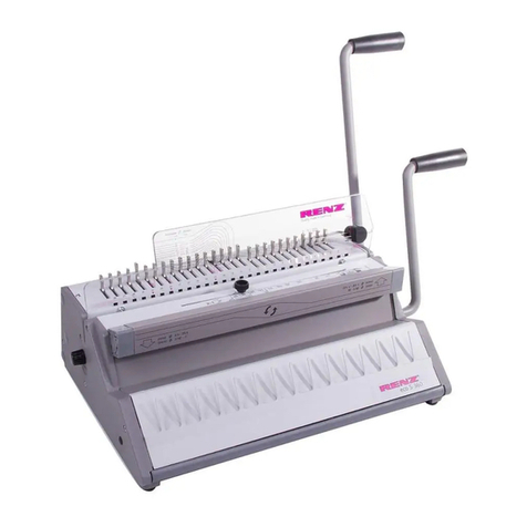
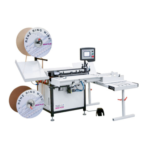
Renz Mobi 360 User manual

Operating instructions
Mobi 360
(semi-automatic RingWire binding machine)
Chr. RENZ GmbH
Rechbergstr. 44
73540 Heubach
Deutschland
Phone: + 49 (0) 7173/186-0
Fax: + 49 (0) 7173/3720
mail@renz-germany.de
www.renz.com
www.renz-germany.de

MOBI360 Table of contents page 2
1 Table of contents
1 Table of contents ...................................................................................................2
2 EC Declaration of Conformity...............................................................................4
3 As-delivered condition of your MOBI360.............................................................5
4 Product description...............................................................................................6
5 General safety advice............................................................................................7
6 Transport and start-up.........................................................................................11
7 RENZ MOBI360 - technical data..........................................................................14
8 RENZ RING WIRE ®Table....................................................................................15
9 Control console and switch................................................................................16
9.1.1 Start screen....................................................................................................................................................17
9.1.2 Settings ..........................................................................................................................................................17
9.1.3 Input screen....................................................................................................................................................17
9.1.4 Parameters:....................................................................................................................................................18
9.1.5 Reference run:................................................................................................................................................18
9.1.6 Automatic mode: ............................................................................................................................................18
10 Setting up the MOBI360.......................................................................................19
10.8.1 Adjusting the stroke limiter:............................................................................................................................23
10.8.2 Adjusting the rear guide rail ...........................................................................................................................24
10.8.3 Adjusting the front guide rail...........................................................................................................................24
10.8.4 Adjusting the clamping...................................................................................................................................25
4.1 Intended use................................................................................................................................6
4.2 Description of operation.............................................................................................................6
4.3 Description of operational sequence ........................................................................................6
5.1 Operator’s duty of care ..............................................................................................................7
5.2 Safety advice...............................................................................................................................7
5.3 Explanation of Symbols .............................................................................................................8
5.4 Safety precautions during normal operation............................................................................9
5.5 Safety precautions during maintenance...................................................................................9
5.6 Work on electrical equipment..................................................................................................10
5.7 Environmental standards.........................................................................................................10
6.1 Safety advice regarding transport...........................................................................................11
6.2 Unpacking the machine............................................................................................................11
6.3 Lifting points when transporting with industrial trucks.........................................................12
6.4 Space requirements and assembly .........................................................................................12
6.5 Electrical connections..............................................................................................................13
6.6 Start- up.....................................................................................................................................13
7.1 Binding formats........................................................................................................................14
7.2 Electrical connections..............................................................................................................14
7.3 Space requirement....................................................................................................................14
7.4 Site conditions..........................................................................................................................14
7.5 Weights......................................................................................................................................14
9.1 Individual screens.....................................................................................................................16
10.1 Changing the RING WIRE spool ..............................................................................................19
10.2 Track of separation paper........................................................................................................19
10.3 Cover for small sizes................................................................................................................20
10.4 Paper guiding rail......................................................................................................................20
10.5 Changing the feed wheel (2:1 or 3:1 pitch) .............................................................................21
10.6 Set up of the feeding section...................................................................................................22
10.7 Adjusting the guide slot on the hanger station ......................................................................23
10.8 Adjusting the closing unit........................................................................................................23

MOBI360 Table of contents page 3
10.8.4.1 Mounting the clamping into the lower position ...........................................................................................25
10.8.4.2 Mounting the clamping into the upper position...........................................................................................26
10.8.4.3 Warning about the T-bar.............................................................................................................................26
10.9.1 Settings ..........................................................................................................................................................27
10.9.2 Clamp settings on the display........................................................................................................................28
10.9.3 Programming the counter...............................................................................................................................28
10.9.4 Preset counter................................................................................................................................................28
10.9.5 Step by step mode .........................................................................................................................................29
10.10.1 Feed test.....................................................................................................................................................31
10.10.2 Parameter settings......................................................................................................................................32
10.11.1 Simple delivery device (standard) ..............................................................................................................33
10.11.2 Conveyor belt (optional) .............................................................................................................................33
11 Short overview "Setting up the MOBI360" ........................................................34
12 KA300(R) hanger dispenser................................................................................35
12.1.1 Installation KA300 ..........................................................................................................................................35
13 Error messages....................................................................................................36
13.1.1 Incorrect input.................................................................................................................................................36
13.1.2 Hanger empty.................................................................................................................................................36
13.1.3 Fault on the hanger device.............................................................................................................................36
13.1.4 Fault in the closing device..............................................................................................................................36
14 Troubleshooting...................................................................................................37
14.1.1 Faults when inserting the hanger...................................................................................................................37
15 Default values and factory settings ...................................................................39
16 some space for your notes .................................................................................40
10.9 Entering display data................................................................................................................27
10.10 Feed test and parameter settings............................................................................................31
10.11 Delivery device..........................................................................................................................33
12.1 KA300 ........................................................................................................................................35
13.1 Error messages on the display................................................................................................36
14.1 Faults when drawing in loops..................................................................................................37
14.2 Faults in transporting of the material to be bound into the closing unit ..............................38
14.3 Poor binding..............................................................................................................................38
14.4 General faults............................................................................................................................38
15.1 Default in the settings display ................................................................................................. 39
15.2 Values in the parameter display ..............................................................................................39

MOBI360 EC Declaration of Conformity page 4
2 EC Declaration of Conformity
According to EC Directives
xEC Machinery Directive 2006/42/EG
xElectromagnetic compatibility according to 2004/108/EG
xLow-voltage 2006/95/EG
The following equipment:
Product: Semi-automatic binding machine
Type: MOBI360
Valid from machine no.: 10099
Year of construction: 08/2011
was developed, designed and manufactured according to the above EC Directives exclusively by
Company: Chr. Renz GmbH, Rechbergstraße 44, D-73540 Heubach
The following harmonised standards were applied:
EN ISO 12100, Safety of Machinery, Basic concepts, general principles for design
EN 60204-1, Safety of Machinery, Electrical Equipment of Machines
.............................................................................................................................................................
.............................................................................................................................................................
.............................................................................................................................................................
.............................................................................................................................................................
The following national standards, guidelines and specifications were applied:
............................................................................................................................................................
............................................................................................................................................................
............................................................................................................................................................
Complete technical documentation is available.
The machine’s manual is available
;in the original version
;in the following European languages: German, English, Italian, Spanish, French,
Heubach, Aug. 2011 Managing Director
(Place, date) Signature (Position)

MOBI360 As-delivered condition of your MOBI360 page 5
3 As-delivered condition of your MOBI360
Machine number: 4036015 .
Year of construction :
Pitch (en): 2:1 3:1
Voltage: V
Frequency : Hz
PLC- program :
Display- program :
Calendar hanger tool: KA s/n . no cal. hanger tool
Delivery device: standard delivery device
conveyor belt
s/n .
Additional accessories :
Heubach, Thursday, 01 December 2011
signature

MOBI360 Product description page 6
4 Product description
4.1 Intended use
The RENZ® MOBI360 binding machine is exclusively intended for binding with a wire comb. As an
option, the wire comb elements can also be cut.
xThe machine is not intended for applications other than those specified here
xNon-compliance with this manual will be considered to be inappropriate use!
In particular, we point out that the following is not allowed:
xThe uses of the machine for purposes other than binding with wire comb elements.
Danger
xIf the MOBI360 is not used in accordance with these requirements, the safe
operation of the machine cannot be guaranteed.
xAny damage to property and persons resulting from inappropriate use is the
responsibility of the operator of the machine, not the manufacturer.
4.2 Description of operation
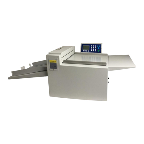
The RENZ MOBI360 is a semi-automatic wire comb binding machine.
It binds wire combs from 50 –500mm in length and a diameter of 3/16" – – 11/4“.
A calendar hanger feed (KA300), available as an option, enables an automatic feed of calendar hangers
during the binding process.
It is possible to skip bind up to 3 elements as standard.
4.3 Description of operational sequence
xThe product to be bound is fitted into the available wire comb elements.
xOn pressing the foot pedal, the product is transported to the right into the binding unit.
xAt the same time a new wire comb is positioned ready (with the KA300 option, the calendar hanger
also drops into the elements).
xThe product is clamped in the binding unit and moved upwards.
xThe upper position is now bound.
xWhen the binding procedure has ended, the closing bar moves back far enough to allow the finished
bound product to slide downward into the magazine.
xThe machine is now ready for a new binding cycle.

MOBI360 General safety advice page 7
5 General safety advice
5.1 Operator’s duty of care
xThe MOBI360 binding machine has been designed and built according to
carefully selected harmonised standards and additional technical specifications.
It therefore meets the latest technical standards, offering the highest possible
level of safety in operation.
xHowever the machine can only be operated safely if all the required steps are
taken. It is a part of the operator’s duty of care to plan for and monitor the
execution of these steps.
In particular the operator must ensure that
xThe machine is only used as intended
xThe machine is only operated when in perfect functional condition and the safety
devices in particular are regularly checked for their functionality.
xExisting safety devices must not to be altered or defeated.
xThe personal safety equipment required for personnel involved in operation,
maintenance and repair must be available and be worn.
xThe manual is legible and complete, and is always available where the machine
is used.
xThe machine may only be operated, serviced and repaired by qualified and
authorised personnel.
xSuch personnel are given regular training in all matters relating to health and
safety and the protection of the environment, and should be conversant with the
manual and in particular the safety advice contained in it.
xAll safety and warning notices attached to the machine should not be removed
and must be legible.
5.2 Safety advice
These operating instructions provide valuable safety advice regarding unavoidable residual risks that
exist in the operation of the machinery.
These residual risks may pose danger to:
xPersonnel, in particular operators
xThe product and the machine
xThe environment

MOBI360 General safety advice page 8
5.3 Explanation of Symbols
The symbols listed below appear in the operating instructions where appropriate, highlighting the
specified residual risks.
Danger
This symbol indicates a particular risk to personnel! (danger to life, risk of injury)
Caution
This symbol indicates a particular risk to the equipment, the material and / or the
environment. (damage, collision)
This symbol indicates an electrical risk. (See also Chapter 5.6) (danger to life, risk of
injury or fire)
This symbol indicates a risk of crushing hands and fingers.
Stickers have been placed on the machine at the relevant position.
The main aim of this health and safety advice is to prevent personal injuries.
xIf a warning triangle marked “Danger” is placed next to safety advice, this does not exclude the
possibility of risks to the equipment, material and / or the environment as well.
xIf the warning triangle indicating electrical danger is placed next to safety advice, this does not
exclude the possibility of risks to the machine, material, environment and personnel.
xIf the warning triangle marked “Warning” is placed next to safety advice, there is no risk to
personnel.
In all cases, the symbol does not replace the text of the safety advice. The text must always be
read thoroughly!
information
This symbol indicates matters of special importance to the operator and/or provides further
information to assist in understanding the workings of the machine.

MOBI360 General safety advice page 9
5.4 Safety precautions during normal operation
xThe machine may only be operated by personnel who are authorised and
trained in its use, who are conversant with the manual and can work according
to the instructions laid down in it.
Before switching on the machine, check and make sure that
xonly authorised personnel are present in the working area around the machine
and that nobody can be injured when the machine starts up.
xbefore starting production, check the machine for visible damage and make
sure that it is only operated if it is in perfect condition! Any defects should be
reported to the operator’s superior immediately.
xbefore starting production, remove all material and items not required for
production from the work area around the machine.
xbefore starting production, ensure all safety devices are functioning correctly!
5.5 Safety precautions during maintenance
Warning
Keep to the inspection and maintenance intervals laid out in the manual.
Pay attention to the repair and maintenance manuals for the individual components in
this instruction booklet.
Before carrying out maintenance or repair work, bar access to unauthorised
personnel in the work area around the machine! Attach or set up a sign drawing
attention to the fact that maintenance or repair work is being carried out.
Before maintenance and repair work is carried out, switch off at the mains and
secure the electricity supply with a padlock. The key to this lock must be in hands of
the person who is carrying out the maintenance or repair work. Furthermore the
machine must be disconnected from the mains.
When changing heavy machine parts, only use only suitable lifting devices and
slinging equipment.
Before maintenance and repair work is carried out ensure that all parts of the
machine with which contact may be made have cooled down to ambient temperature.
Dispose of environmentally hazardous lubricating, cooling or cleaning agents in a
responsible manner.

MOBI360 General safety advice page 10
5.6 Work on electrical equipment
Repair work on electrical equipment in the machine may only be carried out by a
trained electrician.
xExamine electrical equipment regularly.
xTighten loose connections immediately.
xChange damaged conductors / cables immediately.
xAlways keep the switchgear cabinet closed. Access is restricted to authorised
personnel with the appropriate key and tools.
xNever clean switchgear cabinets and other electrical equipment housings by
hosing down with water.
5.7 Environmental standards
When working on, or with the machine, adhere to all legal requirements avoiding the
production of waste, recycling and disposal. It is of particular importance during
installation, repair or maintenance work that the following pollutants do not enter the
groundwater, or drainage system:
xLubricating greases and oils
xHydraulic oils
xCooling agents
xCleaning fluids containing solvents
These materials must placed in suitable containers, transported away from the
machine, collected and disposed of.

MOBI360 Transport and start-up page 11
6 Transport and start-up
6.1 Safety advice regarding transport
Danger
To prevent damage to the machine and possible lethal injuries during transport, the
following should be considered:
xLifting devices and slinging equipment must meet the requirements of the
regulations for the prevention of industrial accidents.
xWhen choosing lifting devices and slinging equipment, take account of the
weight of the MOBI360 (approximately 470kg).
xThe routes over which the equipment is to be transported should be closed off
and marked out such that no unauthorised personnel can enter the danger area.
xThe transport of the equipment may only be carried out by qualified authorised
personnel.
xThe individual components of the machine may only be transported with a fork-
lift truck or a pallet truck that has sufficient load carrying capacity
xUse only those lifting devices that have forks of a sufficient length to reach
through the entire machine frame, thus ensuring safe transport conditions.
xTake note of the position of lifting points in the diagram below
xTransport across ramps should only be attempted with suitable lifting devices
6.2 Unpacking the machine
If the machine has been delivered in a transport crate, please proceed as follows:
xUndo the screws on the upper cover. Remove the cover.
xUndo the screws on the sides and remove them.
xRemove the machine’s rear and side covers.
xRemove the clamps that fasten the machine to the floor of the crate.
xRemove the accessories, which can be found inside the machine.
xUsing a suitable stacker truck, lift the MOBI360 off the floor of the crate.
Danger
xThe sides and the cover of the transport crate are relatively heavy. Two people
are needed to remove these items.
Caution
xWhen transporting the machine and lifting it from the floor of the crate, ensure
the cables are not damaged.

MOBI360 Transport and start-up page 12
6.3 Lifting points when transporting with industrial trucks
xPlace the forks of the stacker truck or pallet
truck as wide apart as possible. Lift the machine
in the centre, by its frame (see diagram on left).
xOn steep slopes, do not use with lifting devices
that have no brakes.
6.4 Space requirements and assembly
xPlease note that for safe operation
of the machine, the operator’s work
space must be sufficiently large.
xThe machine should be set up on
an even and stable surface.
xPlease note the additional space
requirement for opening the
switching cabinet and when using
an optional available conveyor belt.
Caution
xThe weight of the MOBI360 (approximately 470kg without calendar tool) is
distributed over four castors. Take care to ensure that the floor is sufficiently
strong and stable.

MOBI360 Transport and start-up page 13
6.5 Electrical connections
xThe voltage is 230V (single phase) 50Hz [where required, 115V (single phase) 60Hz]
xThe socket must be earthed.
xThe socket must be equipped with a 16 Amp. fuse.
xIf you are uncertain as to whether, or not the socket meets the specification, please
consult an electrician before start-up.
6.6 Start- up
Danger
To prevent people from tripping:
xLay the cable in such a way that there is no risk of tripping (use troughs, bridges
etc.)
To ensure smooth running of the machine:
xPrepare the area such that the machine stands horizontally on an even floor.
xLay the cable such that there is no tensile load placed on the plugs.
xAvoid chafing on the cable.
Information
Before starting the MOBI360 for the first time, check:
xHave all transit supports and desiccation bags been removed?
xIs the electrical connection correct?
xAre all safety devices bolted on?
Information
Before starting the MOBI360 for the first time, the following tasks must be carried
out:
xClean the painted surfaces and the metal parts in the working area with a mild
cleaning agent, in order to remove any traces of rust preventing fluid that has been
applied for transport.

MOBI360 RENZ MOBI360 - technical data page 14
7 RENZ MOBI360 - technical data
7.1 Binding formats
Bound side min. 50 mm - max. 360 mm
Unbound side min. 90 mm
Block thickness max. 27 mm
RENZ RING WIRE£1/4" – 1 1/4 "
Pitches Standard: 3:1 and 2:1
Mechanical output 1000 bindings per hour
7.2 Electrical connections
Voltage See page 5
Average power demand 600 VA
Max. power demand 900 VA
Type of protection IP42
7.3 Space requirement
Length approx. 1,9 m
Width approx. 1.4 m (approx. 2,3m with conveyor belt)
Height approx. 1.8 m
7.4 Site conditions
Ambient temperature (in operation) min. 15°C - max. 35°C
Ambient temperature (when not in use) min. 5°C - max. 50°C
Maximum air humidity: Max. 85% relative air humidity (non-condensing)
7.5 Weights
MOBI360 binder 470 kg (approx. net without calendar device)
MOBI360 with packing (wooden box) 610 kg (approx. gross weight without calendar device)

MOBI360 RENZ RING WIRE ® Table page 15
8 RENZ RING WIRE ®Table
recommended
perforation cross
section in mm
inch mm loops /
inch
max. book
thickness
w/o hanger
max. book
thickness
with hanger
min.
binding
width
max.
binding
width
rectangular
hole round hole
1/4" 6,9 3:1 5,0 3,5 50 500 4,0 x 4,0 ø 4,5
5/16" 8,0 3:1 6,0 4,5 50 500 4,0 x 4,0 ø 4,5
3/8" 9,5 3:1 7,5 6,0 50 500 4,0 x 4,0 ø 4,5
7/16" 11,0 3:1 9,0 7,5 50 500 4,0 x 4,0 ø 4,5
1/2" 12,7 3:1 10,0 50 500 4,0 x 4,0 ø 4,5
9/16" 14,3 3:1 11,0 50 500 4,0 x 4,0 ø 4,5
5/8" 16,0 2:1 13,5 100 500
c
6,0 x 6,0 ø 6,0
3/4" 19,0 2:1 15,0 100 500
c
6,0 x 6,0 ø 6,0
7/8" 22,0 2:1 18,0 100 500
c
6,0 x 6,0 ø 6,0
1" 25,4 2:1 20,0 100 500
c
6,0 x 6,0 ø 6,0
11/8"28,5 2:1 23,0 100 500
c
6,0 x 6,0 ø 6,0
11/4"31,7 2:1 27,0 100 500
c
6,0 x 6,0 ø 6,0
c
In the case of products from 5/8"to 1 1/4 " with product lengths of 300mm to 360mm and full block thickness, problems can occur when
binding due to the weight and condition of the paper. As a result of the higher weight and possibly too little clamping friction between the pages
it is possible that the product is not shifted upward into the binding position correctly. Before processing large numbers, such products should
first be tested on the MOBI360.
Information
xCalendars with hangers should only be bound with diameters from 1/4"to 3/8".
With diameters of 7/16" and above the hanger slides out of the binding.
xPlease refer to the table above when selecting the perforation, the binding
diameter and the block thickness.
xIncreasing the block thickness beyond the values specified above will inevitably
lead to problems in quality and production.

MOBI360 Control console and switch page 16
9 Control console and switch
cTouch screen surface
The touch screen display is not only a display, but is
also used for inputting machine and production data.
Data that can be altered can be changed or deleted
by touching the screen lightly in the relevant
position.
dOn button
Pressing the green button causes power to flow to
the control units and the machine to start operating
eOff button
Pressing the red button switches the machine off.
fPotentiometer for the spool drive
With this potentiometer you can regulate the speed
of the spool payoff.
xPosition "0" = OFF (the wire comb spool is not
paid off )
xPosition "1" - "10" = (the wire comb spool is paid
off. The higher the value, the faster the payoff
speed)
hMain switch
The main switch is on the switchbox door at the back
of the machine.
Danger
xRepair work on electrical equipment in the machine may only be
carried out by a trained electrician.
xOnly authorised personnel are permitted to opening the control box.
xThe control box key is to be stored in a safe place.
9.1 Individual screens
Caution
The touch screen has a contact-sensitive surface. Lightly tapping the appropriate
virtual button triggers the relevant activity. Do not operate the display with hard or
pointed items, as they destroy the surface and thus the function of the display.
Information
Only the grey shaded buttons can be operated on the screens. The other switches
cannot be used.

MOBI360 Control console and switch page 17
9.1.1 Start screen
xA few seconds after switching on the MOBI360, the start
screen appears.
xYou can select the language, set the time , and change
the contrast .
xYou progress onto the next screen by pressing the
button
9.1.2 Settings
xAll the data required to process a particular product can be
entered into the screen.
xAll buttons can be operated and changed.
xPressing the "Parameter" switch causes the screen to
change to parameter settings.
xPressing the switch causes all servo motors and
knives to perform a reference run, following which the
machine changes over to automatic operation.
xAs a special option, the MOBI360 can be equipped with a
"cutting function". The cutting function means that RING
WIRE elements are cut off and ejected. The binding
machine is switched off. If your MOBI360 is equipped with
this function, pressing the button "Cutty" activates this
mode of operation.
9.1.3 Input screen
When operating buttons that require numeric inputs, after
tapping the input screen the following appears:
xcThis area displays the current data entered using the
numeric buttons.
xdNegative values can be entered using this switch (not
required).
xeThis button causes the value in the display to be
accepted. The input screen closes after this button has
been pressed.
xfThis button allows wrongly entered data to be deleted
from the display area.
xgNumeric buttons for entering numerical values.

MOBI360 Control console and switch page 18
9.1.4 Parameters:
xIn the parameter set up screen, the correction factors for the
servo motors can be set.
9.1.5 Reference run:
xThis is a pure information screen. It appears until all the
servomotors and the knife have reached their start positions.
Once the starting positions have been reached, the screen
changes to Automatic or Cut mode (optional).
9.1.6 Automatic mode:
The automatic mode screen displays the currently entered data.
The following values can be changed during automatic operation:,
for example the input speed and switching the calendar feed on
or off. The output counter can be changed and a feed test can be
carried out.
xAutomatic mode/step by step mode
xfeeding speed
xconveyor
xpiece counter (regular/preset)
xT-bar on/off
xhanger on/off
xwire feeding test

MOBI360 Setting up the MOBI360 page 19
10 Setting up the MOBI360
10.1 Changing the RING WIRE spool
Danger
The spring is under pressure. If you open the release handle the spring and the
clamping device possibly jumps off the shaft. It could hurt you or your
colleagues. Please take care when you release the release handle.
xLoosen the release handlecand remove the
clamping devicedand the compression springe
from the shaftf.
xTake the spoolgoff the shaft.
xPush the new spool onto the shaft, so that the
RING WIRE pays off from the left side.
xPush the compression spring and the clamping
device back onto the shaft.
xStretch the compression spring and tighten the
release handle.
xMove the pay-off arm back to a vertical position.
xPlace the feed plate into a slanting position again,
so that the paid off wire rests comfortably on the
switching surface of the initiator
10.2 Track of separation paper
Information
The separation paper will redirected twice and driven by a motor directly into a paper
basket . The separation paper must be fed in manually with each change of spool.
xFirst feed the papercbehind the upper guiding shaftd
xNow feed the paper behind the next guiding shaft and between the
two white guiding partse.
xLift up the upper rollerfand move the paper between the upper and
the lower roller gas long as it goes into your waste paper basket or
card board box.
xIf you operate the Mobi360 the paper will be transported into the
waste paper basket (or whatever you are using).

MOBI360 Setting up the MOBI360 page 20
10.3 Cover for small sizes
Information
To avoid problems during the paper transport into the binding unit with small sizes (smaller
than 150mm) you must install a sheet metal cover.
To install the cover please proceed as following:
xSwitch off the Mobi360 (main switch into pos. "0").
xOpen the protection covereof the binding unit.
xRemove the lower rear wavy railcby removing the three
allen screwsd.
xPut in the sheet metal coverf. It´ s been held by the
magnet stripes at its rear side.
xYou can now operate sizes smaller than 150mm
because this area is now covered and the paper could
not hit any edges.
xIf you want to go back to bigger sizes please switch the
main switch into pos. "0" and assemble the lower rear
clamping rail in reverse action to the above mentioned
sequence.
10.4 Paper guiding rail
Information
xTo move the paper "trouble-free" into the binding unit, you must install the paper guiding
rail.
xThe paper guiding railclifts the paper in its lower area. This makes sure that the paper
will be transported without any resistance. The paper will be high enough to get into the
delivery device.
The paper guiding railclifts the paper in its lower area. This
makes sure that the paper will be transported without any
resistance. The paper will be high enough to get into the
delivery device.
xThe paper guiding rail will be held by magnet stripes. This
enables you to fix it at any place at the front cover.
xMove the paper guiding rail to the lower third of your
product.
xIf you change your size you possibly must change the
position of the paper guiding rail.
Table of contents
Other Renz Binding Machine manuals

Renz
Renz eco s 360 User manual

Renz
Renz eco s 360 User manual

Renz
Renz PBS 340 User manual

Renz
Renz WBS 360 User manual

Renz
Renz Combi Comfort User manual

Renz
Renz Combi S User manual

Renz
Renz RENZ DTP 340A Owner's manual

Renz
Renz Combinette Type 33 Technical manual

Renz
Renz DTP 340 M User manual

Renz
Renz eco 360 comfort plus User manual

Renz
Renz SRW 360 comfort plus User manual

Renz
Renz combi comfort plus User manual

Renz
Renz Eco E User manual

Renz
Renz DTP A 340 User manual

Renz
Renz eco 360 comfortplus User manual

Renz
Renz PBS 340 User manual

Renz
Renz RW 360 User manual

Renz
Renz eco 360 comfortplus User manual

Renz
Renz SPB 360 comfortplus User manual

Renz
Renz WIRE|GO 3:1 User manual