Renz Autobind 500 HS User manual

Manual
Autobind 500 HS
(semi-automatic binding machine)
Chr. RENZ GmbH
Rechbergstr. 44
73540 Heubach
Deutschland
Phone: + 49 (0) 7173/186-0
Fax: + 49 (0) 7173/3720
www.renz.com
www.renz-germany.de

AB500HS
Table of contents page 1
1 Table of contents
1Table of contents ................................................................................................................. 1
2EG conformity declaration .................................................................................................. 3
3AB500HS specific machine datas ...................................................................................... 4
4General Information.............................................................................................................5
4.1 Intended Use..................................................................................................................................................5
4.2 Operating description .....................................................................................................................................5
4.3 Sequence of operation ...................................................................................................................................5
5General Safety Instructions ................................................................................................ 6
5.1 User´s Duty of Care .......................................................................................................................................6
5.2 Safety Instructions..........................................................................................................................................6
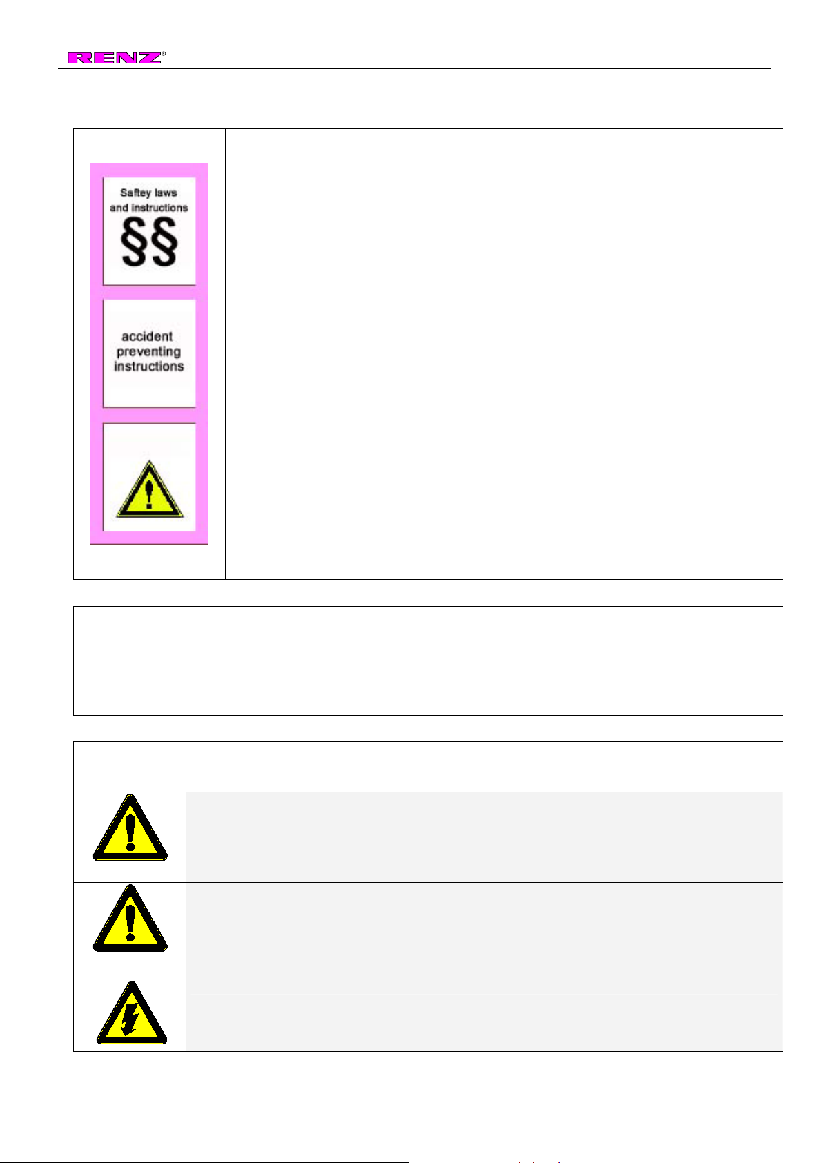
5.3 Description of symbols ...................................................................................................................................6
5.4 Safety Requirements for Normal Operation...................................................................................................7
5.5 Safety Requirements for Maintenance and Servicing....................................................................................7
5.6 Working on Electrical Equipment ...................................................................................................................8
5.7 Working on Pneumatic Equipment.................................................................................................................8
5.8 Environment Protection Regulations..............................................................................................................8
6Transport and Installation................................................................................................... 9
6.1 Safety Instructions for Transport....................................................................................................................9
6.2 Unpack the AB500HS ....................................................................................................................................9
6.3 Support points for transportation..................................................................................................................10
6.4 Space requirement with simple output tray..................................................................................................10
6.5 Space requirement with conveyor (shingle) belt..........................................................................................11
6.6 Electrical connection ....................................................................................................................................11
6.7 Installation ....................................................................................................................................................12
6.8 Installation of the de-spooling device...........................................................................................................12
7RENZ Autobind 500 - Technical data ............................................................................... 13
7.1 Binding format ..............................................................................................................................................13
7.2 Electrical connection ....................................................................................................................................13
7.3 Dimensions ..................................................................................................................................................13
7.4 Environmental conditions.............................................................................................................................13
7.5 Pneumatic requirement ................................................................................................................................13
7.6 Weights ........................................................................................................................................................13
8RENZ RING WIRE®Chart................................................................................................... 14
9Touch-screen display and switches................................................................................. 15
10 Adjustable machine elements ....................................................................................... 16
10.1 Paper side stops.......................................................................................................................................16
10.2 Clamping rail.............................................................................................................................................16
10.3 Table height adjustment ...........................................................................................................................16
10.4 Table front stop position ...........................................................................................................................16
10.5 Closing limiter ...........................................................................................................................................17
10.6 Opening limiter .........................................................................................................................................17
10.7 Simple output tray (optional) ....................................................................................................................17
10.8 Conveyor (shingle) belt.............................................................................................................................18
10.9 Maintenance unit for compressed air .......................................................................................................18
11 Handling of the touch-screen-display........................................................................... 19
11.1 Appearing screens....................................................................................................................................19
11.1.1 Starting screen......................................................................................................................................19
11.1.2 Set up screen........................................................................................................................................19
11.1.3 Operation mode (main menue).............................................................................................................19
11.1.4 Automatic ..............................................................................................................................................20
11.1.5 Manual Operation .................................................................................................................................20
11.1.6 Step by step ..........................................................................................................................................20
11.1.7 Inlet check.............................................................................................................................................21
11.1.8 Display messages.................................................................................................................................21
11.1.9 Input box ...............................................................................................................................................23
11.2 Example 1 for 3:1 pitch (Standard A4 book) ............................................................................................23
11.3 Example 2 for 3:1 pitch (with calendar hanger)........................................................................................25

AB500HS
Table of contents page 2
11.4 Example 3 for 3:1 pitch (skip binding) ......................................................................................................27
11.5 Programming for 2:1 pitch ........................................................................................................................28
12 Changing of the RING WIRE spool................................................................................ 28
13 Adjustment of the binding unit...................................................................................... 29
13.1 Changing of inlet channel and feeding wheel ..........................................................................................29
13.1.1 Changing of the inlet channel ...............................................................................................................29
13.1.2 Changing of the feeding wheel and height adjustment of the knife......................................................30
13.1.3 Changing of the closing bar ..................................................................................................................31
13.1.4 Adjusting the opening limitation ............................................................................................................32
13.1.5 Adjusting the closing limitation..............................................................................................................32
13.2 Binding table adjustments ........................................................................................................................33
13.2.1 Paper clamping rail ...............................................................................................................................33
13.2.1.1 Adjustment of the left side .............................................................................................................33
13.2.1.2 Adjustment of the right side ...........................................................................................................33
13.2.2 Side stops .............................................................................................................................................34
13.2.2.1 Adjustment of the paper side stops ...............................................................................................34
13.2.2.2 Installation and adjustment of the loop side stop ..........................................................................34
13.2.3 Table height ..........................................................................................................................................35
13.2.4 Front stop position of the table .............................................................................................................35
13.2.5 Adjustments in the automatic mode display .........................................................................................36
13.2.6 Ajust the output section.........................................................................................................................37
13.2.6.1 Adjust the conveyor (shingle) belt (CB120HS)..............................................................................37
13.2.6.2 Adjustment of the simple output tray (optional) .............................................................................38
14 Trouble shooting AB500HS............................................................................................ 38
15 Calendar hanger tool (KAS)/optional ............................................................................ 42
15.1 Technical data KAS ..................................................................................................................................42
15.2 Product information KAS unit ...................................................................................................................42
15.3 Sequence of operation .............................................................................................................................42
15.4 Closing bar protection cover.....................................................................................................................42
15.5 Connect the KAS at the AB 500HS ..........................................................................................................43
15.6 Set the KAS to different shaft lengths ......................................................................................................44
15.7 Adjustment of the KAS unit according to your product.............................................................................45
15.8 Adjustment of the slider inclination...........................................................................................................45
15.9 Supply the KAS unit with compressed air ................................................................................................46
15.10 Trouble shooting KAS unit........................................................................................................................47
16 Maintenance .................................................................................................................... 48
16.1 Regular maintenance work.......................................................................................................................48
17 For your notes................................................................................................................. 49

AB500HS
EG conformity declaration page 3
2 EG conformity declaration
according to the EG guidelines
- EG guidelines for machines 2006/42/EG
- electromagnetic consistency 2004/108/EG
- low tension 2006/95/EG
The construction of the machine/system
Model SEMI-AUTOMATIC BINDING MACHINE
Type AUTOBIND 500 HS
Machine no. 7541
Year of construction 02/2010
was developed, constructed and produced in accordance with the EG guidelines 89/392/EWG and with the sole
responsibility of
Company: Chr. Renz GmbH, Rechbergstraße 44, D-73540 Heubach
The following harmonized specifications were applied:
EN ISO 12100, security of machines, units and systems
EN 60 204-1, electrical equipment for industrial machines
..............................................................................................................................................................................
..............................................................................................................................................................................
..............................................................................................................................................................................
..............................................................................................................................................................................
The following national norms, guidelines and specifications were applied:
..............................................................................................................................................................................
..............................................................................................................................................................................
..............................................................................................................................................................................
..............................................................................................................................................................................
A complete technical documentation as well as the relevant manual is available.
The operating manual for the machine is available
;in the original version
;in the European languages German, English, Spanish,
Heubach, 02/2010
(place, date) signature General Manager

AB500HS
AB500HS specific machine datas page 4
3 AB500HS specific machine datas
Machine number : 405002200.7591
Year of construction : 02/2011
Pitch : 2:1 3:1 4:1
Voltage : 230V
Frequency : 50Hz
SPS / PLC program : AB_HS_V60_FX3U
Display program : AB_HS_V61_FX3U
Closing tools delivered together with the Autobind:
∅No. yes no
∅No. yes no ∅No. yes no
3/16" R1/4" 3980 R 5/16" 3984 R
3/8" R7/16" R 1/2" 3977 R
9/16" R5/8" 3943 R 3/4" 3942 R
7/8" R1" 3684 R 1 1/8" R
Calendar hanger unit:: KAS300 s/n 43300000561.4318 without KAS
Conveyor belt: CB120HS s/n 4350022135. without CB120HS
output tray: yes no
Special equipment :
additional closing bar 1/4" s/n 3981R
Heubach, Wednesday, February 08, 2012
signature

AB500HS
General Information page 5
4 General Information
Caution
Please read this manual very carefully before installing or starting the
Autobind 500HS
4.1 Intended Use
The RENZ®AutoBind 500 (subsequent named AB500HS) is a binding machine for Ring Wire
elements. Optional you can cut Ring Wireelements.
•Any other use is not allowed. Each operator has to be familiar with all safety regulations and the
intended purpose of the machine.
•The machine is not intended for types of use other than those listed here. Any infringement of this is
considered improper use!
We would like to draw particular attention to the fact that it is forbidden:
•to do other jobs like binding (and optional Ring Wirecutting) with the AB500HS
Caution
•If the AB500HS is not used in accordance with this requirement, safe use of the
machine cannot be guaranteed.
•The user, and not the manufacturer, of the machine is liable for all personal and
material damage arising from improper use.
4.2 Operating description
The RENZ®AB 500 is a semi automatic binding machine to close double loop wire from 100mm –
500mm working width and a diameter range from 3/16” – 1 1/8”. Additional equipment (KAS-unit)
enables you to bind calendar with hangers. Skip binding up to 10 elements are possible in standard
configuration.
4.3 Sequence of operation
•The product has to be placed at the front and side stops at the table.
•By pressing the foot pedal the clamping device and the front stop angle of the binding table moves
down.
•If a KAS is installed the delivery slider moves forward and the table follows with the product.
•Now the lower closing bar moves upwards and pushes the narrow loops through the perforation and
therefore closes the Ring Wire.
•The lower closing bar moves down and synchronous the holding rail of the upper closing bar lifts up
to provide enough space for the product to come out of the closing bars.
•The table moves back, the clamping is opened, the front stop angle comes up and the holding bar of
the upper closing bar comes down.
•If you have activated the function "belt on" the product will be removed sidewards from the table by
the belts.
•Parallel a new section of loops will be feed into the closing bars. The machine is ready for the next
cycle.

AB500HS
General Safety Instructions page 6
5 General Safety Instructions
5.1 User´s Duty of Care
•The RENZ®AB500HS binding machine has been designed and built after
careful selection of the harmonised standards to be complied with and of
other technical specifications. It is state-of-the-art technology and enables a
very high degree of safety during operation.
•Machine safety can however only be converted into operational practice if all
the action required for this has been taken. The planning of this action and
the control of its implementation fall under the duty of care of the user of the
machine.
The user must especially ensure that
•the machine is only used as intended.
•the machine is only operated in perfect working order and the safety
equipment in particular is regularly inspected as regards its fitness for
operation.
•necessary personal protective equipment for operating, maintenance and
repair personnel is available and is worn.
•the operating manual is always in a legible condition and is fully available at
the site the machine is used.
•only qualified and authorised personnel operate, maintain and repair the
machine.
•this personnel is regularly trained in all relevant matters of Health and Safety
and Environmental Protection, as well as knowing the operating manual and
in particular the safety instructions contained in it.
•all safety instructions and warnings applied to the machine itself are not
removed and are legible.
5.2 Safety Instructions
In this operating manual concrete safety instructions are given to indicate the residual risks that cannot
be avoided when operating the machine. These residual risks include risks to
•People, in particular the operating personnel
•Product and machine
•Environment
5.3 Description of symbols
Symbols indicated below are used in the appropriate place in the operating manual to indicate notably
the named residual risks!
Danger
This symbol indicates that there are, above all, hazards to people!
(Danger to life, risk of injury)
Caution
This symbol indicates that there are, above all, hazards to machine, material and
environment! (Damage, collision, loss of data)
This symbol indicates that there are, above all, hazards to people by electricity.
(see also information chapter 5.7) (Danger to life, risk of injury and risk of fire)

AB500HS
General Safety Instructions page 7
The most important objective of the safety instructions is to prevent people from being injured.
•If there is a warning triangle in front of a safety instruction with the caption “Danger”, hazards to
machinery, material and environment are not excluded.
•If there is a warning triangle in front of a safety instruction that contains a jagged arrow, hazards to
machinery, material and environment are not excluded.
•If there is a warning triangle in front of a safety instruction with the caption “Caution”, hazards to
people are however not anticipated.
The respective symbol used may not replace the text of the safety instruction. For this reason
the text must always be read in its entirety!
Information
This symbol identifies points, which are of particular importance for the operator and / or
serves as information for a better understanding of the operating sequences of the
machine!
5.4 Safety Requirements for Normal Operation
The machine may only be operated by trained and authorised personnel who
are familiar with the operating manual and are capable of working in
accordance with the manual! Before turning the machine on, check and ensure
that Only authorised personnel are in the working area of the machine!
No one may be injured when the machine starts! Every time you start
production, inspect the machine for visible damage and ensure that it is
operated only in perfect working order! The supervisor must be informed of any
faults that have been noticed! Every time you start production, clear any
material and objects that are not required for production from the working area
of the machine! Every time you start production, check and ensure that all
safety equipment is working perfectly!
5.5 Safety Requirements for Maintenance and Servicing
•Adhere to the inspection and maintenance intervals specified in the operating manual!
•Comply with the maintenance and repair instructions for the individual components in this operating
manual!
Before carrying out maintenance or repair work, block access to the working area of
the machine by unauthorised personnel! Attach or put up a sign that draws attention to
the maintenance or repair work!
Before carrying out maintenance and repair work turn off the main isolator switch for
the power supply and lock it with a padlock! The key to this lock must be in the hands
of the person carrying out the maintenance or repair work!
When replacing heavy machine components, use only appropriate and perfectly
operating lifting equipment and accessories! Before carrying out maintenance and
repair work ensure that all parts of the machine that may be touched have cooled down
to ambient temperature!
Properly dispose of lubricants, coolants or cleaning materials that may harm the
environment!

AB500HS
General Safety Instructions page 8
5.6 Working on Electrical Equipment
Repair work on electrical equipment of the machine may only be carried out by a trained
and skilled electrical personnel!
•Regularly inspect electrical equipment!
•Retighten loose connections!
•Immediately replace damaged leads/cables!
•Always keep the electrical cabinet closed! Access is only permitted to authorised
personnel with key/tool!
•Never clean electrical cabinets and other electrical equipment casings by spraying
them down with a water hose!
5.7 Working on Pneumatic Equipment
¾Only allow maintenance and repair work on pneumatic equipment to be carried out
by specially trained personnel!
¾Before carrying out maintenance and repair work remove the pressure from the
pneumatic equipment of the machine!
¾Regularly replace pipelines through preventive maintenance even when no damage
is visible!
Before starting the machine after maintenance or repair work:
•check that loosened screw connections are securely fitted.
•ensure that container covers, screening equipment or filters that have been
removed are re-installed.
•remove all materials, tools and other equipment necessary for maintenance or
repair work from the working area of the machine.
•check all machine safety equipment for perfect operation!
5.8 Environment Protection Regulations
In the case of all work on and with the machine, statutory obligations for waste
avoidance and proper recycling/disposal are to be complied with!
In particular in installation, repair and maintenance work, substances hazardous to
water such as
•Lubricant greases and oils
•Hydraulic oils
•Coolants
•Cleaning fluids containing solvent
may not pollute the ground or may not enter the sewerage system!
These substances must be stored, transported, collected and disposed of in
suitable containers!

AB500HS
Transport and Installation page 9
6 Transport and Installation
6.1 Safety Instructions for Transport
Danger
In order to exclude damage to the machine and highly dangerous injuries during
transport the following are to be observed:
•Lifting equipment and accessories must meet the requirements of the
regulations for the prevention accidents!
•The weight of the AB500HS (about 290 kg) should be taken into consideration
when choosing the lifting equipment and accessories!
•Transport routes should be blocked off and marked so that no unauthorised
party may enter the danger area!
•Transport work may only be carried out by qualified and authorised personnel!
•Individual machine components may only be transported with a forklift or
pallet truck with an adequate load bearing capacity!
•Only use lifting equipment with forks long enough to extend through the whole
machine frame to ensure safe conditions during transport!
•Take note of the support points for lifting the machine shown in the sketch
below!
•Use only lifting apparatus to transport the machine over ramps!!
Danger
•Movement is only allowed with fork lifts or pallet trucks with an adequate load
bearing capacity.
•The AB500HS can tilt if you move on uneven or slanting surfaces.
6.2 Unpack the AB500HS
If the machine was delivered in a wooden crate please proceed as follows (to unpack the machine):
•Release the screws for the top cover and remove the top cover.
•Release the screws for the side frames and remove them.
•Remove the rear and the side sheet metal cover of the machine.
•Remove the clamping devices for machine fixing.
•Lift the AB500HS off the pallet with a suitable fork lift or a crane.
Danger
•The covers of the wooden crate are very heavy. Please remove them with a
minimum of two people.
Caution
•Do not damage any cable and wiring during the transportation and lifting.

AB500HS
Transport and Installation pa
g
e
6.3 Support points for transportation
Set the forks of the pallet truck/forklift truck as
wide as possible and lift the machine in the
centre! Do not use manual pallet jacks without a
brake if you want to move the machine on
declinations.
6.4 Space requirement with simple output tray
~2,05mtr.
~1,96mtr.
•Please ensure that for the safe
operation of the machine the working
area of the operating personnel is of
an adequate size.
•Set the machine up on a level
surface.
Caution
The full weight of the AB500HS (approx. 240kg without closing tools or KAS unit) will
be put on the four adjusting feet. Please make sure that your floor has enough load
capacity.

AB500HS
Transport and Installation pa
g
e
6.5 Space requirement with conveyor (shingle) belt
~2,11mtr.
~1,97mtr.
•Please ensure that for the
safe operation of the
machine the working area
of the operating personnel
is of an adequate size.
•Set the machine up on a
level surface.
6.6 Electrical connection
•The standard voltage is 230V (1 ph.) 50Hz [115V (1ph.) 60Hz on request]
•The socket must have a protective wire (PE)
•The socket must be secured with 16 Amps.
If you are not sure that your socket is fulfilling the specifications please consult an
electrician before you install the AB500HS.

AB500HS
Transport and Installation pa
g
e
6.7 Installation
Danger
To avoid the risk of tripping up:
•Lay the connecting cable in such a way as to avoid creating any tripping points (Use
of cable conduits, bridges etc.)!
To ensure fault-free operation:
•Prepare the installation site so that the machine is level on an even floor!
•Lay the connecting cable so that that there is no tensile strain on the connectors!
•Avoid chafing points on the connecting cable!
Information
Before starting the AB500HS for the first time check:
•Have all transport securing devices and desiccant bags been removed?
•Is the electrical connection correct?
•Are all safety devices operational?
Information
Before starting the AB500HS for the first time, without fail carry out the following
procedures:
•Clean all painted and metal surfaces in the working area with a mild cleaning agent
to remove residues of rust proofing materials applied for transport!!
6.8 Installation of the de-spooling device
•Remove the two screwseof the de-
spooling devicec.
•Put the de-spooling device into the
square pipedat the left side of the
machine frame.
•Fix the de-spooling device with the two
screwse.
•Plug in the plug for the de-spooling
device into the socketf.
•Hold the sheet metal guiding deviceg
at the upper areaiwith your hand.
Release the two small clamping
handlesh.
•Adjust the slope of the sheet metal
guiding device according to the sketch
beside.
•Tighten the two clamping handles.

AB500HS
RENZ Autobind 500 - Technical data pa
g
e
7 RENZ Autobind 500 - Technical data
7.1 Binding format
Bound product min. 60 mm - max. 500 mm
Unbound edge with/without autom. ejection min. 100 mm
Book thickness max. 23 mm
RENZ RING WIRE3/16“ – 1 1/8"
Pitch standard: 3:1 and 2:1(4:1 optional)
Mechanical capacity 2000 bindings per hour
7.2 Electrical connection
Voltage see page 4
average power requirement 340 VA
max. power requirement 600 VA
system of protection IP42
7.3 Dimensions
length approx. 1,65m
depth approx. 1,56m
height approx. 1,70m
7.4 Environmental conditions
Environmental temperature (operation): min. 15°C - max. 35°C
Environmental temperature (storage): min. 5°C - max. 50°C
Max. humidity: max. 85% rel. humidity (not condensing)
7.5 Pneumatic requirement
air pressure requirement 300-340 Lit./mincat 7-7,5 bar (101-108psi)
max. source pressure 10 bar (145psi)
cdepends on using KAS-unit or not
7.6 Weights
AB500HS binding unit 240kg (approx. net without closing tools or KAS unit)
with shipping crate 390kg (approx. net without closing tools or KAS unit)
load capacity of floor 500kg/m2

AB500HS
RENZ RING WIRE® Chart pa
g
e
8 RENZ RING WIRE®Chart
∅minimum size of perforation
in mm
square hole round hole
inch mm
pitch
max. book
thickness
without
hanger
max. book
thickness
with hanger
min.
binding
width
max.
bindin
g width
3/16“ 4,8 3:1 3,0 60 500 4,0 x 4,0 Ø 4,0
1/4“ 6,9 3:1 4,5 3,5 60 500 4,0 x 4,0 Ø 4,5
5/16“ 8,0 3:1 6,0 5,0 60 500 4,0 x 4,0 Ø 4,5
3/8“ 9,5 3:1 7,5 6,5 60 500 4,0 x 4,0 Ø 4,5
7/16“ 11,0 3:1 9,0 8,0 60 500 4,0 x 4,0 Ø 4,5
1/2“ 12,7 3:1 10,0 60 500 4,0 x 4,0 Ø 5,0
9/16“ 14,3 3:1 11,0 60 500 4,5 x 4,5 Ø 5,0
5/8“ 16,0 2:1 13,5 100 420 6,0 x 6,0 Ø 6,0
3/4“ 19,0 2:1 15,0 100 420 6,0 x 6,0 Ø 6,5
7/8“ 22,0 2:1 18,0 100 420 6,5 x 6,5 Ø 6,5
1“c25,4 2:1 20,0 100 420 6,5 x 6,5 Ø 7,0
11/8d“ 28,5 2:1 23,0 100 420 6,5 x 6,5 Ø7,0
Information
•Calendars can only be bound in the sizes 1/4" to 7/16". When you bind 7/16“ the
calendar hanger can slide out of the binding.
•Please adhere to the numbers in the above chart.
•Increasing of the book thickness or decreasing of the perforation size may lead
to difficulty with production.
c
Operating the AB500HS with 1" may cause some unexpected problems. We recommend to de-activate the belt
function while working with 1".
dOperating the AB500HS with 1 1/8"the automatic belt function must be de-activated at all. The belt function is
not processable with this diameter.

AB500HS
Touch-screen display and switches pa
g
e
9 Touch-screen display and switches
cTouch Screen display
The touch screen display is not only for data
display but also for entry of the machine and
production data. Any data can be changed or
deleted at the respective position by touching the
display.
dSwitch on button
Push the green button to start the machine
(power on switch)
eRheostat for spool motor
This switch controls the speed of the spool de-
winding.
0 = OFF
10 = ON, max. de-winding speed
fEmergency-off switch
This switch interrupts the entire power supply and
the machine stops immediately.
gMain switch
The main switch is at the switch box on the back
of the machine.
DANGER!
Even if the main switch is off, there is still voltage in the control box.
Repair and maintenance work should only be carried out by qualified
personnel. The key of the switching cabinet must be stored secured. In
no case it may lie unattended openly.

AB500HS
Adjustable machine elements pa
g
e
10 Adjustable machine elements
10.1 Paper side stops
•At the left side of the machine table, there are the two side stopsc
which can be adjusted to align the holes in the paper with the RING
WIRE®elements in the closing bar.
10.2 Clamping rail
•The clamping railcis mounted transversely over the front
area of the machine table. It helps to secure the product
to be bound during the transport into the closing bar. The
opening height of the clamping rail can be adjusted
according to the diameter of the RENZ RING WIRE®
element selected.
10.3 Table height adjustment
•According to the used diameter you have to adjust the front stop
position of the table. The screwcenables you to adjust the front
stop position. The screw is located at the lower front side of the
binding table.
10.4 Table front stop position
•According to the used diameter you have to adjust the front stop
position of the table. The screwcenables you to adjust the front
stop position. The screw is located at the lower front side of the
binding table.

AB500HS
Adjustable machine elements pa
g
e
10.5 Closing limiter
•With the closing limiter knobcyou can adjust on how far you want to
close your RENZ RING WIRE® element.
10.6 Opening limiter
•The distance between the lower and the upper closing bars must be
adjusted according to the used diameter. The adjusting wheelc
enables you to adjust the distance.
10.7 Simple output tray (optional)
The output tray could be placed beside the
AB500HS instead of the conveyor belt.
•You can adjust the height by releasing the
clamping lever and lifting the upper section up or
down.
•The slope is adjustable as well. Release the
according clamping lever and adjust the slope of
the upper part.
•For different sizes there is a guiding sheet metal
in the output tray. You can move it to any place in
the tray and it is been held by a magnetic tape.

AB500HS
Adjustable machine elements pa
g
e
10.8 Conveyor (shingle) belt
Usually the AB500HS is equipped with a
conveyor or shingle belt device.
•You can adjust the conveyor by releasing
the clamping levers.
•The area for the paper output is variable to
be able to adjust different products.
Danger
Please adjust the height of the conveyor only with a minimum of two persons. If you
release the clamping levers the upper part of the conveyor immediately starts
falling down and possibly hurts you.
10.9 Maintenance unit for compressed air
•At the right side of the machine, the maintenance unit
becomes accessible after the sheet metal cover has been
opened. This maintenance unit prepares the compressed
air for the machine. The air is dried and kept at a constant
pressure. The water trap functions automatically when the
water in the water container reaches a certain height, a
float valve opens and the water is drained off.
•The standard operation pressure is set at about 7-7,5 bar
(101- 109psi). when the machine is delivered. This
pressure can be changed by turning the pressure setting.
Attention!! do not set more than 8,0 bar (116psi)
•(A higher pressure may be required for larger diameters).
If the pressure will fall below 5,5 bar (80psi), an error
message is shown on the display.
•The air supply for the calendar hanger tool (KAS) is
turned off and on by pushing and turning the manual KAS
supply valve.
Caution
Never set the pressure higher than 8,0 (116psi) bar. By higher mechanical load you
will damage possibly some components at your AB500HS.

AB500HS
Handling of the touch-screen-display pa
g
e
11 Handling of the touch-screen-display
Caution
Never ever use hard, sharp or pointed items to operate the Touch screen display.
You might destroy the surface of the Display and as for this the display and the
AB500HS is not operatable any longer.
11.1 Appearing screens
11.1.1 Starting screen
•After you switched on the AB700 the display carry out a
system check. This takes a few seconds. After this check
the starting screen appears. It contains the program
version and the manufacturers address.
•By touching the arrows at the left and right of the
language box you can change the display language.
•By touching the “Kontrast” button you can change the
Kontrast of your display.
•By touching the area of the word „Next“ the screen
changes to the menu „set up“.
11.1.2 Set up screen
•The “set up” menu directly appears after the starting
screen. You also can open it in the “operation mode”
menu.
•The „set up“ menu is for setting the data like pitch, no. of
loops, calendar hanger on/off and the feeding speed.
•By touching the „Next“ button the initial run starts. After
finishing the reference run the display changes to the
„Operation mode“ menu.
11.1.3 Operation mode (main menue)
automatic
manual operation
step by step
wire feeding check
<==
==>
Set up
exit
¾production mode
¾you can operate each single function
manually
¾operate a complete binding cycle
step by step
¾slow loop feeding and cutting for
testing and adjusting the main drive.
¾Moves the wire at the feeding wheel
to the left
¾Moves the wire from the feeding
wheel to the knife
¾for input of no. of loops, pitch, cal.
hanger on/off etc.
¾back to the starting screen.
This manual suits for next models
1
Table of contents
Other Renz Binding Machine manuals

Renz
Renz Mobi 360 User manual

Renz
Renz RENZ DTP 340A Owner's manual

Renz
Renz SRW 360 User manual

Renz
Renz SRW 360 comfort User manual

Renz
Renz WBS 360 User manual

Renz
Renz private bind User manual

Renz
Renz PBS 340 User manual

Renz
Renz Combi S User manual

Renz
Renz PBS 340 User manual

Renz
Renz DTP A 340 User manual

Renz
Renz COMBINETTE User manual

Renz
Renz eco 360 comfortplus User manual

Renz
Renz Combi E User manual

Renz
Renz SRW 360 comfort plus User manual

Renz
Renz Renz ERW User manual

Renz
Renz RW 360 User manual

Renz
Renz eco 360 comfortplus User manual

Renz
Renz Combi Comfort User manual

Renz
Renz eco s 360 User manual

Renz
Renz Eco E User manual