manuals.online logo
Brands
  1. Home
  2. •
  3. Brands
  4. •
  5. Saxby Lighting
  6. •
  7. Lighting Equipment
  8. •
  9. Saxby Lighting ICARUS PIR 2LT WALL User manual

Saxby Lighting ICARUS PIR 2LT WALL User manual

www.saxbylighting.com
Instruction manual
81011
ICARUS PIR 2LT WALL
Saxby Lighting. BH17 7BY
V2 14/04/2021
We recommend cleaning with a soft dry cloth. Do not use solvents or abrasive cleaners as these could damage the finish.
For your safety, always switch off the power supply before changing lightbulbs, or cleaning.
Care and Safety
Technical data
240 V~, 50 Hz
Supply
Voltage:
Bulb
Type: 2 x Max. 5W LED GU10
Conformity with all relevant EC Directive requirements.
The power supply is double insulated and does not require connection to an Earth circuit.
Waste electrical products should not be disposed of with household waste. Please recycle where facilities
exist. Check with your Local Authority or local store for recycling advice.
This product is rated at IP44.
IP
44
Fitting/replacing bulbs: Max. 5W LED GU10
• This fitting has been designed to use energy efficient LED bulbs. Ensure that the minimum
distance to the illuminated surface is not less than 0.5m (50cm).
• When changing a bulb, always switch off at the mains and allow the bulb to cool before handling. Dispose of used bulbs
carefully. Do not exceed the wattage stated or use a different shape bulb from that indicated on the fitting. Use of the incorrect
bulb will damage the product and invalidate the guarantee.
0.5m
This product is rated at IK05.
IK05
PIR Adjustment
To access the adjustment screws flip down the black cover over the PIR sensor. Take great care when adjusting the
sensor screws not to over tighten as they can be easily broken.
POWER ON AUTO MODE
MANUAL MODE
1
23
• When first switched on, the PIR sensor “warms up” for approx 1 minute and then goes into AUTO mode.
• In AUTO mode, switch the power OFF and ON twice within 3 seconds, the PIR sensor will switch to MANUAL mode.
In MANUAL mode, the light will remain ON permanently, without the PIR function.
• To return to AUTO mode, switch the power OFF and ON twice within
3 seconds.
• In either mode, if the power is switched OFF more than 6 seconds,
the PIR sensor will go through 'warm up' process again when you turn
it on next time.
The PIR sensor has a manual override function which can be operated by taking the following steps:
• The unit must be installed in a vertical position, and fitted 1.8-2.5m above the ground.
• The PIR sensor can be adjusted, allowing the detection
distance to be altered to suit the location. The detection
angle is set at 110º. The duration that lamp stays on can
also be altered from 5 seconds - 5 minutes. The LUX
rang is 10-2000 lux. Use a small screwdriver to adjust
the "TIME" and "SENS" screws. When adjusting the
sensitivity (detection distance) in daylight it will be
necessary to cover the sensor to simulate night time.
Adjustable up to 8 metres PIR Adjustment
1.8- 2.5Metres
4M 6M
8M
appro. 110º
Warning
Please read these instructions carefully before commencing any work.
This unit must be fitted by a competent and qualified electrician.
Install in accordance with the IEE Wiring regulations and current Building Regulations.
Check the pack and make sure you have all the parts listed.
To prevent electrocution switch off at the mains supply before installing or maintaining this fitting.
Ensure other persons cannot restore the electrical supply without your knowledge.
If you are in any doubt, please consult a qualified electrician.
If replacing an existing fitting, make a careful note of the connections.
This light should be connected to a circuit with a 30mA RCD fitted.
This product is suitable for location in or near a marine environment.
The entire unit gets hot whilst on for a period of time, ensure the fitting is mounted out of arms reach.
Waste electrical products should not be disposed of with household waste. Please recycle where facilities exist. Check with
your local authority or retailer for recycling advice.
Thank you for purchasing this light fitting. Please read the instructions carefully before use to ensure safe and satisfactory
operation of this product. Please retain these instructions for future reference.
Layout
Plan the desired layout of these fittings carefully, ensuring the cables will reach the distances between the junction box and the
each light fitting.
Avoid locating any cables in positions that would cause a hazard. Position cables and outdoor rated junction boxes
(not supplied) away from areas where they may be at risk from being cut, trapped or damaged.
We recommend that you use H05RN-F specification cable (not supplied) which is an outdoor grade, rubber sheathed cable.
The mains supply cable must have a minimum cross section area of 1.0mm2.
Cables must be protected using suitable conduit or plastic trunking.
Commissioning
Installation
This light fitting is double insulated and does
not require connection to an Earth circuit.
Existing fittings must be completely removed before installation of a new product. Before removing the existing fitting, carefully
note the position of each set of wires.
Note that the switch is turned off before installation.
Ensure that the screws and cable entry points are sealed to maintain the IP rating of the product.
After deciding the layout of the light fittings ensure that the cables are long enough to connect to desired positions.
• Determine the position of your light fitting taking into account the entry position of the cable and the ARROW indicating
which WAY UP the base is to be fitted. Make sure there is sufficient cable coming out of the wall to connect to the terminal
block. Ensure that the mounting surface is solid, preferably a brick or block wall and ensure that there are no other cables
or pipes beneath the surface.
• Diagram A. Fit the 2 threaded posts in the back plate and bring the mains cable through the rubber grommet then use the
back plate as a template and mark the 2 fixings holes, making sure the back plate is correctly aligned so that the threaded
bolts are horizontal. Use appropriate fixings to secure the back plate to the wall. Ensuring the drain hole is at the base
of the mounting box.
• Diagram B. Connect the house wiring to the internal terminal block. The cable entry grommet must be securely in place to
ensure that the water ingress protection is maintained. NOTE: This is a Class II fitting and must not be earthed. If you
have any earth cables make sure that they are connected to each other – to maintain earth continuity throughout your
property – and wrap the earth terminal and connections in 2 layers of good quality insulation tape and keep them
away from the terminal connections of the fitting. Connect the incoming mains as per the diagram.
Having correctly identified the wiring from your light fitting, connect to the approved outdoor rated external terminal block in
the following way:
Wiring
SUPPLY LIGHT FITTING
SWITCHED LIVE
NEUTRAL BLUE (N)
BROWN (L)
Check that...
You have correctly identified the wires
The connections are tight
Diagram C.
(1)
Diagram A.Diagram A.
Fixing screws
Fixing screws
Mains cable
Threaded bolts
Diagram B.
Incoming Supply Internal Cables
Switched Live
Neutral
Brown or Labelled - L
Blue or Labelled - N
L
N
No loose strands have been left out of the connection block
Reseal the approved outdoor rated external terminal block
Drain hole
• Diagram C. Fit the terminal block onto the post in the back plate and then
fit the front frame over the 2 threaded bolts in the back plate and secure with
the 2 threaded nuts. Take care not to trap or strain the internal cables.
• Fit the appropriate bulbs into the lamp holders NOTE: Never fit bulbs of a
higher wattage than specified on the label (as this may cause overheating
and damage the fitting).
• Replace the bulb covers (1).
• Replace fuse or circuit breaker and switch on. Your light is now ready for use.
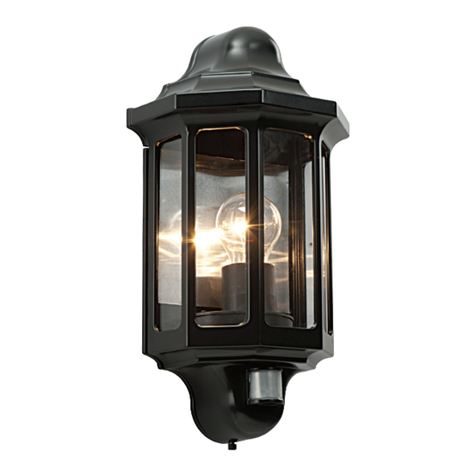
This manual suits for next models

1

Other Saxby Lighting Lighting Equipment manuals

Saxby Lighting Aqualine 24V Manual

Saxby Lighting

Saxby Lighting Aqualine 24V Manual

Saxby Lighting 10430 Manual

Saxby Lighting

Saxby Lighting 10430 Manual

Saxby Lighting Axial Rectangular User manual

Saxby Lighting

Saxby Lighting Axial Rectangular User manual

Saxby Lighting Varone 55702 Manual

Saxby Lighting

Saxby Lighting Varone 55702 Manual

Saxby Lighting SMART IKON User manual

Saxby Lighting

Saxby Lighting SMART IKON User manual

Saxby Lighting 46393 Manual

Saxby Lighting

Saxby Lighting 46393 Manual

Saxby Lighting Reeve Connect Batten Series Manual

Saxby Lighting

Saxby Lighting Reeve Connect Batten Series Manual

Saxby Lighting 81572 User manual

Saxby Lighting

Saxby Lighting 81572 User manual

Saxby Lighting 75430 User manual

Saxby Lighting

Saxby Lighting 75430 User manual

Saxby Lighting 13929 User manual

Saxby Lighting

Saxby Lighting 13929 User manual

Saxby Lighting 101626 User manual

Saxby Lighting

Saxby Lighting 101626 User manual

Saxby Lighting Lucca Mini User manual

Saxby Lighting

Saxby Lighting Lucca Mini User manual

Saxby Lighting SHIELDPRO CCT 90376 User manual

Saxby Lighting

Saxby Lighting SHIELDPRO CCT 90376 User manual

Saxby Lighting Icarus Twin Wall EL-40054 Manual

Saxby Lighting

Saxby Lighting Icarus Twin Wall EL-40054 Manual

Saxby Lighting Sight ECO User manual

Saxby Lighting

Saxby Lighting Sight ECO User manual

Saxby Lighting Lucca Wall 67176 Manual

Saxby Lighting

Saxby Lighting Lucca Wall 67176 Manual

Saxby Lighting 72641 Manual

Saxby Lighting

Saxby Lighting 72641 Manual

Saxby Lighting Hero CCT User manual

Saxby Lighting

Saxby Lighting Hero CCT User manual

Saxby Lighting 43787 Manual

Saxby Lighting

Saxby Lighting 43787 Manual

Saxby Lighting Odyssey Bollards ST501228 User manual

Saxby Lighting

Saxby Lighting Odyssey Bollards ST501228 User manual

Saxby Lighting Lucca Wall User manual

Saxby Lighting

Saxby Lighting Lucca Wall User manual

Saxby Lighting OrionSMART User manual

Saxby Lighting

Saxby Lighting OrionSMART User manual

Saxby Lighting 75272 Manual

Saxby Lighting

Saxby Lighting 75272 Manual

Saxby Lighting 79192 User manual

Saxby Lighting

Saxby Lighting 79192 User manual

Popular Lighting Equipment manuals by other brands

hidealite LEDstrip Neon Top manual

hidealite

hidealite LEDstrip Neon Top manual

EuroLite LED Techno Strobe 250 EC user manual

EuroLite

EuroLite LED Techno Strobe 250 EC user manual

Facom 779.EYE instruction manual

Facom

Facom 779.EYE instruction manual

Genaray SSL-MINI-B user manual

Genaray

Genaray SSL-MINI-B user manual

Mercura GYROLED M80 Mounting

Mercura

Mercura GYROLED M80 Mounting

Philips GreenPower LED Quick installation guide

Philips

Philips GreenPower LED Quick installation guide

Sunricher SRP-2309-75-TW-CC quick start guide

Sunricher

Sunricher SRP-2309-75-TW-CC quick start guide

ADJ PRO38B LED RC User instructions

ADJ

ADJ PRO38B LED RC User instructions

Soundoff Signal Pinnacle EPL7000 Series instruction sheet

Soundoff Signal

Soundoff Signal Pinnacle EPL7000 Series instruction sheet

Conrad 77 72 24 operating instructions

Conrad

Conrad 77 72 24 operating instructions

Bruck 700052 instruction manual

Bruck

Bruck 700052 instruction manual

Robus RHA2WEMPK-PSU instruction manual

Robus

Robus RHA2WEMPK-PSU instruction manual

Inspire LEDFLEXI 2128KS-1.5-RGBW-P instruction manual

Inspire

Inspire LEDFLEXI 2128KS-1.5-RGBW-P instruction manual

THORLABS DC3100 Series Operation manual

THORLABS

THORLABS DC3100 Series Operation manual

Heitronic 35374 Installation and operating instructions

Heitronic

Heitronic 35374 Installation and operating instructions

HITLIGHTS Echo Setup guide

HITLIGHTS

HITLIGHTS Echo Setup guide

GTV TIAGO LD-TIAGOGU10D-20 user manual

GTV

GTV TIAGO LD-TIAGOGU10D-20 user manual

Aladdin AMS-FL50B1 product manual

Aladdin

Aladdin AMS-FL50B1 product manual

manuals.online logo
manuals.online logoBrands
  • About & Mission
  • Contact us
  • Privacy Policy
  • Terms and Conditions

Copyright 2025 Manuals.Online. All Rights Reserved.