manuals.online logo
Brands
  1. Home
  2. •
  3. Brands
  4. •
  5. Saxby Lighting
  6. •
  7. Lighting Equipment
  8. •
  9. Saxby Lighting IkonPRO RGB LED Kit User manual

Saxby Lighting IkonPRO RGB LED Kit User manual

www.saxbylighting.com
Instruction manual
59136, 59138
IkonPRO RGB LED Kit
We recommend cleaning with a soft dry cloth. Do not use solvents or abrasive cleaners as these could damage the finish.
Care and Safety
Technical data
RF Control
220-240V~, 50Hz
Supply
Voltage:
Bulb
Type:
59136----10 x 0.75W LED module, RGB
59138----10 x 1.5W LED module, RGB
The power supply is Double Insulated and does not require connection to an Earth circuit.
Waste electrical products should not be disposed of with household waste. Please recycle where facilities
exist. Check with your Local Authority or local store for recycling advice.
This product is suitable for dimming with remote control.
This product is rated at IP67.
IP
67
Class III product - designed to be supplied from a SELV
(Separated or Safety Extra-Low Voltage) power source.
Output: 12V DC 15W Max. Constant voltage
To prolong the life and condition of the product, it is recommended that periodically it is cleaned using a
soft cloth followed by the application of a light coating of oil, such as WD40.
Do not clean the units with a pressure washer.
Conformity with all relevant EC Directive requirements.
Conformity with all relevant UKCA Directive requirements.
Live Voltages may be present in the transformer even when turned off or when completely disconnected.
For your safety, always switch off the supply before maintaining the system.
V6 26/11/2021
EU Manufacturer: Brilliant AG,
Brilliantstrasse 1, D-27442 Gnarrenburg
UK Manufacturer: BH17 7BY
RGB
Decrease
Brightness
On / Off
Button
Increase
Brightness
Function Control
Button
The LED module of this luminaire is not replaceable, when the LED module reaches its end of life the whole
luminaire shall be replaced
Push the plug into the mains socket and switch on.
Slide the battery cover off the RF controller and fit the battery
observing the correct polarity markings.
Press the On / Off button on the RF controller. The red LED should
light at the top, and the signal LED should light on the power supply.
Push the RGB button to switch between the different colours. There
are seven individual colours and then two variable modes.
The fixed colour sequence is yellow, white, red, green, blue, purple
and light blue.
There are two variable modes. One switches between all seven
colours and the other fades between them.
The sequence will repeat from the start.
Warning
Please read these instructions carefully before commencing any work
This unit must be fitted by a competent and qualified electrician.
Install in accordance with the IEE Wiring regulations and current Building Regulations.
Check the pack and make sure you have all the parts listed.
This system operates at Safety Extra Low Voltage (12V), via a transformer. Never connect the
light fittings directly to the mains without using a transformer.
The mains plug must be situated indoors (e.g. house, garage, shed) in order to protect it from the elements.
Do not exceed the driver load. For 59136 The supplied driver can operate up to a maximum of 20 LED heads; For 59138, the
supplied the supplied driver can operate up to a maximum of 10 LED heads.
Always disconnect the plug from the mains when installing or maintaining this system.
This system contains non-replaceable parts and cannot be serviced. If damage occurs the part should be scrapped.
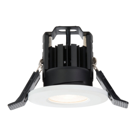
The LED heads and driver are rated at IP67. They are suitable for installation in very wet areas, but must not be permanently
submerged. The driver must not be installed directly in the soil.
Rated maximum surface temperature is 80 ºC.
Waste electrical products should not be disposed of with household waste. Please recycle where facilities exist.
Check with your local authority or retailer for recycling advice.
Thank you for purchasing this light fitting. Please read the instruction carefully before use to ensure safe and satisfactory
operation of this product. Please retain these instruction for future reference.
Layout
Plan the desired layout of these fittings carefully, ensuring the cables will reach the distances between the mains plug, the LED
driver and each light fitting.
Installation
Existing fittings must be completely removed before installation of a new product. Before removing the existing fitting, carefully
note the position of each set of wires.
Avoid locating any cables in positions that would cause a trip hazard. Position cables and driver away from areas where they
may be at risk from being cut, trapped or damaged.
The power supply is Double Insulated and does not require connection to an Earth circuit.
The LED units are Safety Extra Low Voltage and must not be earthed.
Kit Layout Diagram
10 heads per kit
The mains plug must be situated indoors. The kit can be wired into an IP67 external terminal block. (recommended terminal
block ref. 90131/90132). This must be carried out by a competent and qualified electrician.
The driver and LED head units are rated at IP67 and can be positioned outdoors.
These fittings are designed to be used in decking and must not be
mounted/installed in concrete and should only be mounted in
vertical surfaces (only horizontally mounted).
This LED kit has been specifically designed for use in decking and combines some innovative features to make installation
easier:-
- 2 x prewired looms each with 5 LED heads plus a 5m extension cable allowing longer runs to be achieved.
- The wiring loom can be fitted into the deck during construction.
- Heads are interchangeable allowing different sizes and colours to be operated from one power source.
1. Position the plug next to the indoor mains outlet socket that the system will connect to. Do not plug-in at this stage.
2. After deciding the layout of the light fittings, ensure the cables are long enough to connect to the desired positions. The
maximum distance between heads is 1.5m.
3. Drill the mounting holes for the light units taking care not to damage any pipes or mains cables beneath the mounting
surface. Minimum hole depth is 80mm (A).
Cutting hole sizes are as follows:-
- 25mm diameter lights = 20mm cutting hole
- 45mm diameter lights = 32mm cutting hole
4. From underneath the decking, feed the connector and cable up through each installation hole (B).
5. Fit the protective cap onto the connector - to prevent the unit from dropping back through the hole and to keep debris out.
6. Once the decking has been fully assembled and the lights are ready to be installed, remove the protective cap and push the
LED head unit onto the connector observing the correct polarity (align the flat part of the connector to ensure correct
connection). (C).
7. Fit the assembled head units by pushing them into the holes. The springs on the side of the head will secure the head units
in place. (D)
8. Connect all looms together and connect directly to the driver output cable, or the extension cable.
9. Ensure any unused heads and cable ends are fitted with the end plug and protective cap to prevent the ingress of moisture.
10. Plug the mains plug into the socket and switch on to test.
A B C D
If not using the supplied plug then the product must be wired to an IP67 (or higher rated) terminal block
(recommended terminal block ref. 90131/90132).
Having correctly identified the wiring from your existing light fitting, connect to the approved outdoor rated external terminal
block in the following way:
Wiring
You have correctly identified the wires.
The connections are tight.
No loose strands have been left out of the
connection block.
Check that...
NEUTRAL
SWITCHED LIVE
BLUE (N)
BROWN (L)
SUPPLY LIGHT FITTING
The Kit contains:
1 x IP67 rated driver with 3 metres of mains cable and mains plug
1 x remote control
1 x 5m extension cable
2 x 5 LED head looms (total length 7.5m per loom)
12 x end plugs
Rubber end cap
15W
On RGB kits, the driver and remote control receiver are combined into one unit. The remote control operates via Radio
Frequency (RF) so to ensure efficient operation, position the
receiver unit appropriately.

This manual suits for next models

2

Other Saxby Lighting Lighting Equipment manuals

Saxby Lighting 10430 Manual

Saxby Lighting

Saxby Lighting 10430 Manual

Saxby Lighting Pillo Plus CCT User manual

Saxby Lighting

Saxby Lighting Pillo Plus CCT User manual

Saxby Lighting Eris Manual

Saxby Lighting

Saxby Lighting Eris Manual

Saxby Lighting Reeve Connect Batten Series Manual

Saxby Lighting

Saxby Lighting Reeve Connect Batten Series Manual

Saxby Lighting Icarus Twin Wall EL-40054 Manual

Saxby Lighting

Saxby Lighting Icarus Twin Wall EL-40054 Manual

Saxby Lighting 75922 Manual

Saxby Lighting

Saxby Lighting 75922 Manual

Saxby Lighting Albus CCT User manual

Saxby Lighting

Saxby Lighting Albus CCT User manual

Saxby Lighting EL-20079 Manual

Saxby Lighting

Saxby Lighting EL-20079 Manual

Saxby Lighting 108750 User manual

Saxby Lighting

Saxby Lighting 108750 User manual

Saxby Lighting Seina 78637 User manual

Saxby Lighting

Saxby Lighting Seina 78637 User manual

Saxby Lighting 73796 User manual

Saxby Lighting

Saxby Lighting 73796 User manual

Saxby Lighting 97818 User manual

Saxby Lighting

Saxby Lighting 97818 User manual

Saxby Lighting ICARUS PIR 2LT WALL User manual

Saxby Lighting

Saxby Lighting ICARUS PIR 2LT WALL User manual

Saxby Lighting 67360 User manual

Saxby Lighting

Saxby Lighting 67360 User manual

Saxby Lighting HeroPro CCT Emergency User manual

Saxby Lighting

Saxby Lighting HeroPro CCT Emergency User manual

Saxby Lighting 75272 Manual

Saxby Lighting

Saxby Lighting 75272 Manual

Saxby Lighting Orion20 User manual

Saxby Lighting

Saxby Lighting Orion20 User manual

Saxby Lighting Surge PIR User manual

Saxby Lighting

Saxby Lighting Surge PIR User manual

Saxby Lighting Surge PIR Manual

Saxby Lighting

Saxby Lighting Surge PIR Manual

Saxby Lighting 43810 Manual

Saxby Lighting

Saxby Lighting 43810 Manual

Saxby Lighting 79192 User manual

Saxby Lighting

Saxby Lighting 79192 User manual

Saxby Lighting 13801 User manual

Saxby Lighting

Saxby Lighting 13801 User manual

Saxby Lighting shieldLED 400 Manual

Saxby Lighting

Saxby Lighting shieldLED 400 Manual

Saxby Lighting Flexline 73670 Manual

Saxby Lighting

Saxby Lighting Flexline 73670 Manual

Popular Lighting Equipment manuals by other brands

Equinox Systems Megabar System EQLED63 user manual

Equinox Systems

Equinox Systems Megabar System EQLED63 user manual

Chauvet COLORado Deco Quad 1 Tour user manual

Chauvet

Chauvet COLORado Deco Quad 1 Tour user manual

PLG PIVOT user manual

PLG

PLG PIVOT user manual

Heitronic Sidra 501232 Installation and operating instructions

Heitronic

Heitronic Sidra 501232 Installation and operating instructions

Robus RHA58405FT-24 instructions

Robus

Robus RHA58405FT-24 instructions

Hope R4 Vision instruction manual

Hope

Hope R4 Vision instruction manual

ProLights LUMA 1500SH user manual

ProLights

ProLights LUMA 1500SH user manual

Martin VC-Feeder user manual

Martin

Martin VC-Feeder user manual

Ayra ITA3D 710 user manual

Ayra

Ayra ITA3D 710 user manual

as-Schwabe Acculine Multi operating instructions

as-Schwabe

as-Schwabe Acculine Multi operating instructions

LITESHEET BriteCor AC Direct BSS installation manual

LITESHEET

LITESHEET BriteCor AC Direct BSS installation manual

HandyLux NECK LIGHTPRO Instructions for use

HandyLux

HandyLux NECK LIGHTPRO Instructions for use

Lightolier LED undercabinet lighting system Installation

Lightolier

Lightolier LED undercabinet lighting system Installation

Martin Professional MiniMAC Wash user manual

Martin Professional

Martin Professional MiniMAC Wash user manual

Gavita Pro 1000e manual

Gavita

Gavita Pro 1000e manual

Uplus Lighting 750 BSWF user manual

Uplus Lighting

Uplus Lighting 750 BSWF user manual

Robus RSN10040DAS4-04 quick start guide

Robus

Robus RSN10040DAS4-04 quick start guide

Beamz LED PARBAR 4Way Tricolor instruction manual

Beamz

Beamz LED PARBAR 4Way Tricolor instruction manual

manuals.online logo
manuals.online logoBrands
  • About & Mission
  • Contact us
  • Privacy Policy
  • Terms and Conditions

Copyright 2025 Manuals.Online. All Rights Reserved.