Warning
Please read these instructions carefully before commencing any work.
This unit must be fitted by a competent and qualified electrician.
Check the pack and make sure you have all the parts listed.
Install in accordance with the IEE Wiring regulations and current Building Regulations.
To prevent electrocution switch off at mains supply before installing or maintaining this fitting. Ensure other persons cannot
restore the electrical supply without your knowledge. If you are in any doubt, please consult a qualified electrician.
If replacing an existing fitting, make a careful note of the connections.
This product is not suitable for location in or near a marine environment.
The entire unit gets hot whilst on for a period of time.
Waste electrical products should not be disposed of with household waste. Please recycle where facilities exist. Check with
your local authority or retailer for recycling advice.
Thank you for purchasing this light fitting. Please read the instructions carefully before use to ensure safe and satisfactory
operation of this product. Please retain these instructions for future reference.
Layout
Plan the desired layout of these fittings carefully, ensuring the cables will reach the distance between the junction
box and the light fitting.
Avoid locating any cables in positions that would cause a hazard. Position cables and outdoor rated junction boxes
(not supplied) away from areas where they may be at risk from being cut, trapped or damaged.
We recommend that you use H05RN-F specification cable (not supplied) which is an outdoor grade, rubber sheathed cable.
The mains supply cable must have a minimum cross sectional area of 1.0mm2.
Cables must be protected using suitable conduit or plastic trunking.
This prodcut has special protection against the ingress of moisture and is IP54 rated.
Product must only be installed into vertical walls.
Installation
This power supply is Double Insulated and does
not require connection to an Earth circuit.
Determine the position of your light fitting taking into account the entry position of the cable and make sure there is sufficient
cable coming out of the wall to connect to the terminal block. Ensure that the mounting surface is solid, preferably a brick or
block wall and ensure that there are no other cables or pipes beneath the surface.
• Carefully pierce a small hole in the rubber gasket in the centre of the mounting box to allow the cable to pass through.
• Thread the cable through the hole, ensuring the drain hole is at the base of the mounting box.
• Attach the rear housing to the wall using the supplied fixings. The correct fixings should be used for brick or cavity walls.
• Wire as detailed Wiring diagram.
• Ensure that the cable is not snagged and seal to maintain the IP rating of the product.
•Adjust the CCT switch to choose you preferred colour or adjust the PIR datas by the DIP Switch(Refer to the detaied PIR
adjustatle seciton).
• Reattach the PC diffuser and front plate to rear housing by refitting the screws and nuts set aside earlier.
• Replace fuse or circuit breaker and switch on. Your light is now ready for use.
•Unscrew the two nuts located at the top and bottom fitted with the front panel, then unscrew the six screws fitted in the
PC diffuser to separate the rear housing from the product. Keep nuts and screws safe for refitting later.
• Using the rear housing as a template, mark and drill the fixing holes. Ensure the wall is capable of holding the
weight of the product. Take care to avoid damaging any concealed wiring and pipes.
Existing fittings must be completely removed before installation of a new product. Before removing the existing fitting, carefully
note the position of each set of wires.
Note that the switch is turned off before installation.
Ensure that the screws and cable entry points are sealed to maintain the IP rating of the product.
PIR Adjustment
•The unit must be installed in a vertical position and the optimum mounting height is 1.8m-2.5m above the ground
• The PIR Sensor on the fitting has the default setting, allow to adjust by the DIP
Switch inside the product. Before setting, you need to unscrew the two nuts
located at the top and bottom fitted with the front panel, then unscrew the six
screws fitted in the PC diffuser to separate the rear housing from the product.
• See below examples Diagram and examples to aid with setting. A small tool
may be required to push the switches.
• When adjusting the sensitivity (detection distance) in daylight it will be
necessary to cover the sensor to simulate night time.
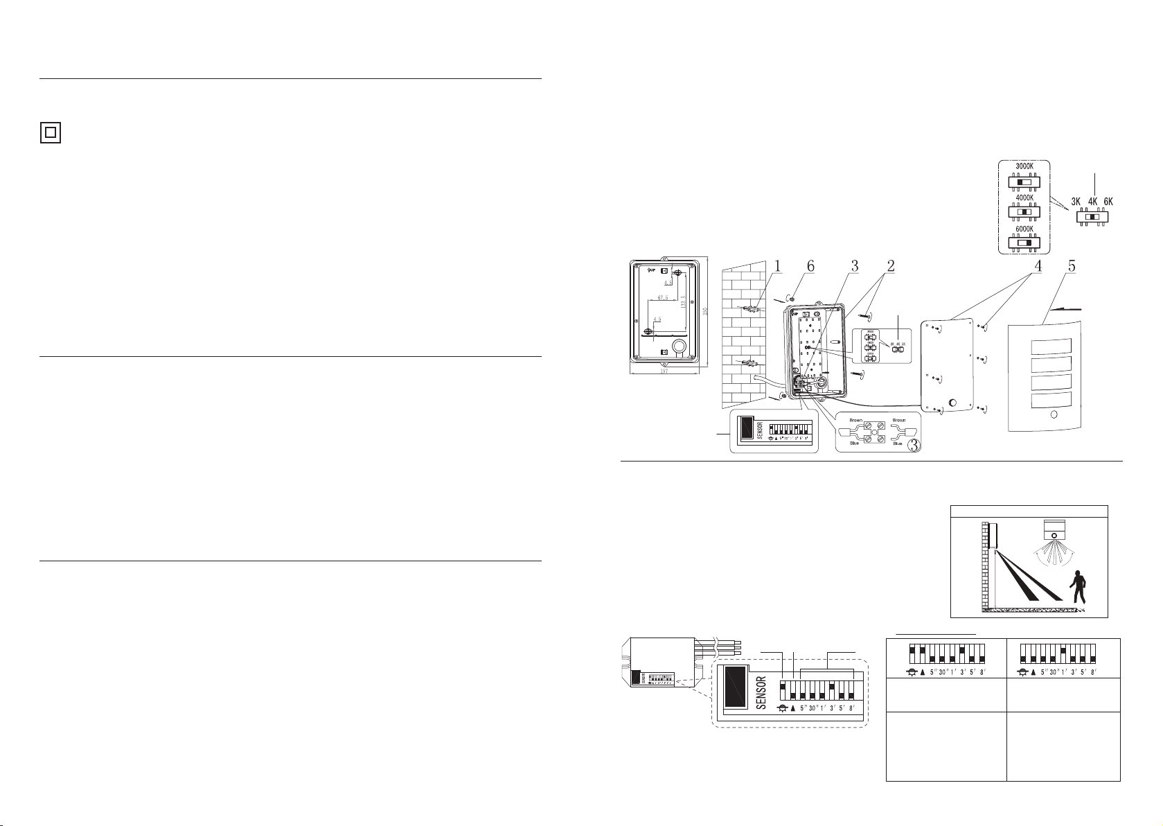
CCT Switch
CCT Switch
DIP Switch
This product is colur changing and can be either warm white (3000K) or
cool white (4000K) or daylight white (6000K).
Choose your preferred colour before installing by sliding the CCT switch inside the product.
Note: Befeore you change the colour, please turn off the power switch for safety.
installation backboard
Max 7 metres (when the SENS is sensitivity 100%)
1.8- 2.5Metres
4M
7M
appro. 100º
Default Setting:
LUX: Night, when the lux is less than 30Lux, the lamp is on.
SENS: Sensitivity 100%, the detecton distance is Max. 7m
TIME: 3 minutes
SETTING EXAMPLES:
a) Works only in darkness,
b) Low sensitivity
c) 3 minute ‘TIME ON’
The fitting will only work during
hours of Darkness. when the lux
is less than 30Lux, the lamp is on.
The PIR has low sensitivity, the
detection distance will is about 4M.
The light will stay on for 3 minutes
once activated.
The fitting will only work all the
time.
The PIR has low sensitivity, the
detection distance will is Max. 7M.
The light will stay on for 1 minute
once activated.
a) Works in night and day,
b) High sensitivity
c) 1 minute ‘TIME ON’
LUX
Switch
‘TIME ON’
Switch
Sensitivity
Switch


