Sharp AR-SP2 User manual

CODE: 00ZARSP2//A2E
Digital copier option
Single Pass Feeder
(SPF)
MODEL AR-SP2
SHARP CORPORATION
Parts marked with "!" is important for maintaining the safety of the set. Be sure to replace these parts with specified
ones for maintaining the safety and performance of the set.
This document has been published to be used
for after sales service only.
The contents are subject to change without notice.
[1] PRODUCT OUTLINE . . . . . . . . . . . . . . . . . . . . . . . . . . . . . . . . . . . . 1
[2] SPECIFICATIONS . . . . . . . . . . . . . . . . . . . . . . . . . . . . . . . . . . . . . . 1
[3] UNPACKING AND INSTALLATION . . . . . . . . . . . . . . . . . . . . . . . . . 1
[4] EXTERNAL VIEW AND INTERNAL STRUCTURE . . . . . . . . . . . . . 4
[5] OPERATIONAL DESCRIPTION . . . . . . . . . . . . . . . . . . . . . . . . . . . . 5
[6] DISASSEMBLY AND ASSEMBLY . . . . . . . . . . . . . . . . . . . . . . . . . . 6
[7] MAINTENANCE . . . . . . . . . . . . . . . . . . . . . . . . . . . . . . . . . . . . . . . 11
[8] ELECTRICAL SECTION . . . . . . . . . . . . . . . . . . . . . . . . . . . . . . . . . 12
CONTENTS

[1] PRODUCT OUTLINE
This unit is installed to the top of the copier to feed document auto-
matically. Documents are automatically transported to the copier to
allow continuous copying.
[2] SPECIFICATIONS
Document set
direction Face up
Document set
position Centerreference
Documenttransport
system Sheet through type
Document feed
sequence Top takeup
Document size AB series: A3 ∼A5
Inch series: 11 ×17 ∼8.5 ×5.5
Documentweight 56 ∼90g/m2
Document set
quantity 30 sheets (30 sheets, 90 g/m2)
Max. thickness 4mm
Dimensions 583mm (W) ×435mm (D) ×131mm (H)
Weight About 5.3 Kg
Power source Supplied from the copier.
Document size
detection Document feed tray upper
Detectionsize Japan: A3, B4, A4, A4R, B5, B5R
Inch series: 11 ×17, 8.5 ×14, 8.5 ×11, 8.5 ×11R,
8.5 ×5.5
EX AB series: A3, B4, A4, A4R, A5
Multi copy Models without memory:
S →S unavailable S →D unavailable
(Duplex copy model only)
Models with memory copy:
S →S allowed S →D unavailable
(Duplex copy model only)
With the electronic sort board:
S →S allowed S →D allowed
(Duplex copy model only)
Document mixture Mixture paper feed:
Copy mode: Unavailable
FAX mode: Allowed (Same width)
Random paper feed Unavailable
Documentreverse None
Displaysection
(LED) None
Document
replacementspeed S →S: 16 sheets/min
(Document replacement rate 100%)
[3] UNPACKING AND
INSTALLATION
1. Unpacking
2. Installation
(1) Package contents
Name Quantity
Screw 2
SPF glass holding cover 1
SPF harness 1
Ring core 1
Installation manual 1
∗Be careful not to use the removed screws in different locations.
1) Remove the document cover.
Lift the document cover and remove it from the copier.
– 1 –

2) Remove the rear cabinet of the copier.
Remove the seven screws and remove the cabinet.
Remove the connector cover.
∗If a open/close detection is attached, be careful not to break the
actuator.
3) Remove the right cabinet.
Remove the five screws.
4) Remove the document glass holder (left side) and the
document glass.
Remove the two screws and carefully remove the document glass
holder (left side) and the document glass. Do not separate the glass
and holder.
5) Remove the document glass holder cover (right side).
Remove the two screws.
6) Attach the cushion (one position).
Remove the cover of the double-sided adhesive tape and paste the
cushion taking care not to allow it to extend over the plate edges.
7) Attach the SPF glass holder cover.
After attaching the SPF glass holding cover, attach the document
glass.
8) Remove the PWB shield plate.
Remove the six screws.
– 2 –

9) Install the SPF harness and the ring core (included
together with the unit).
Pass the SPF harness through the plate hole from the above and fix it
to the plate with the supplied two hex cap screws. (1)
Pass the SPF harness through the ring core (2), and connect it to the
main PWB connector (CN11) inside the copier. (3)
10) Install the SPF to the copier.
Tilt the SPF backward and insert the hinges into the hinge guides.
11) Install the interface harness.
Connect the interface harness from the SPF to the machine and
tighten the screws.
12) Remove the filament tape.
Remove the filament tape at four positions.
Connect the power cord, turn the main switch ON, and
perform the following procedure.
13) Check the magnification ratio.
Place a document on the document glass and make a copy.
Then, place a document in the automatic document feeder tray and
make a copy.
∗If the copy magnification ratio of the copy made with the automatic
document feeder is different than that of the copy image made with
the document glass, perform the magnification adjustment accord-
ing to the procedure in the service manual.
14) Check the center displacement.
Place a document on the document glass and make a copy.
Then, place a document in the automatic document feeder tray and
make a copy.
∗If the center of the copy from the automatic document feeder is
displaced from the copy from the document glass, adjust the cen-
ter according to the procedure in the service manual.
15) Check the leading edge margin.
Place a document on the document glass and make a copy.
Then, place a document in the automatic document feeder tray and
make a copy.
∗If the leading edge margin of the copy from the automatic docu-
ment feeder is displaced from the copy from the document glass,
adjust the margin according to the procedure in the service
manual.
16) Check the open/close detection position.
(only models with original size detection)
If the open/close detection position measured by the open/close
detection position adjustment method in the service manual is outside
the specified values, adjust the position in accordance with the
manual.
(1)
(3)
(2)
★Be careful about the direction
of the connector.
– 3 –

[4] EXTERNAL VIEW AND INTERNAL STRUCTURE
1. External view
No. Name No. Name No. Name
1 Document set tray 2 Document guide 3 Document feed section cover
4 Document transport section cover 5 Document exit section
2. Internal structure
Sensors and detectors
No. Code Name Type Function, operation
1 W0 Document set sensor Photo transmission Document presence detection
2 COVER Open/close sensor Photo transmission Paper feed unit open/close detection
3 W1 Document sensor (A4R, LTR, A5) Photo transmission Tray document width detection
4 W2 Document width sensor (B4R, B5) Photo transmission Tray document width detection
5 W3 Document width sensor (WLTR, A5R, A4, LT) Photo transmission Tray document width detection
6 PSOL Pickup solenoid — —
7 PAPER Paper entry sensor Photo transmission Document presence detection
9 CLH Transport clutch — —
10 MOT SPF motor Stepping motor Tray paper feed, transport, paper exit roller
drive
12 — Interface PWB —SPF control and communication with the copier
body
13 L1 Document length detection SW (Short) Photo transmission Tray document length detection
14 L2 Document length detection SW (Long) Photo transmission Tray document length detection
15 COVER OPEN Book sensor Photo transmission Detects SPF floating.
12
3
4
5
12
3
4
5
6
7
9
10
12
13
14
15
– 4 –

[5] OPERATIONAL DESCRIPTION
1. Paper feed section major parts
No. Part name Operation
1 Document length
sensor (L2) Detects the document length on
the tray.
2 Document length
sensor (L1) Detects the document length on
the tray.
3 Document length
sensor (W0) Detects the presence of
document.
4 Document width sensor
(W1, W2, W3) Detects the document width.
5 Pickup roller Picks up the document.
6 Paper feed roller Feed and transport the
document.
7 Paper entry sensor
(PAPER) Detects the document transport.
8 PS roller Makes synchronization between
the document lead edge and the
image lead edge.
9 PS follower roller Makes synchronization between
the document lead edge and the
image lead edge.
10 Transport roller Transports the document.
11 Transport follower roller Transports the document.
12 Paper exit follower roller Discharges the document.
13 Paper exit roller Discharges the document.
2. Brief descriptions of operations
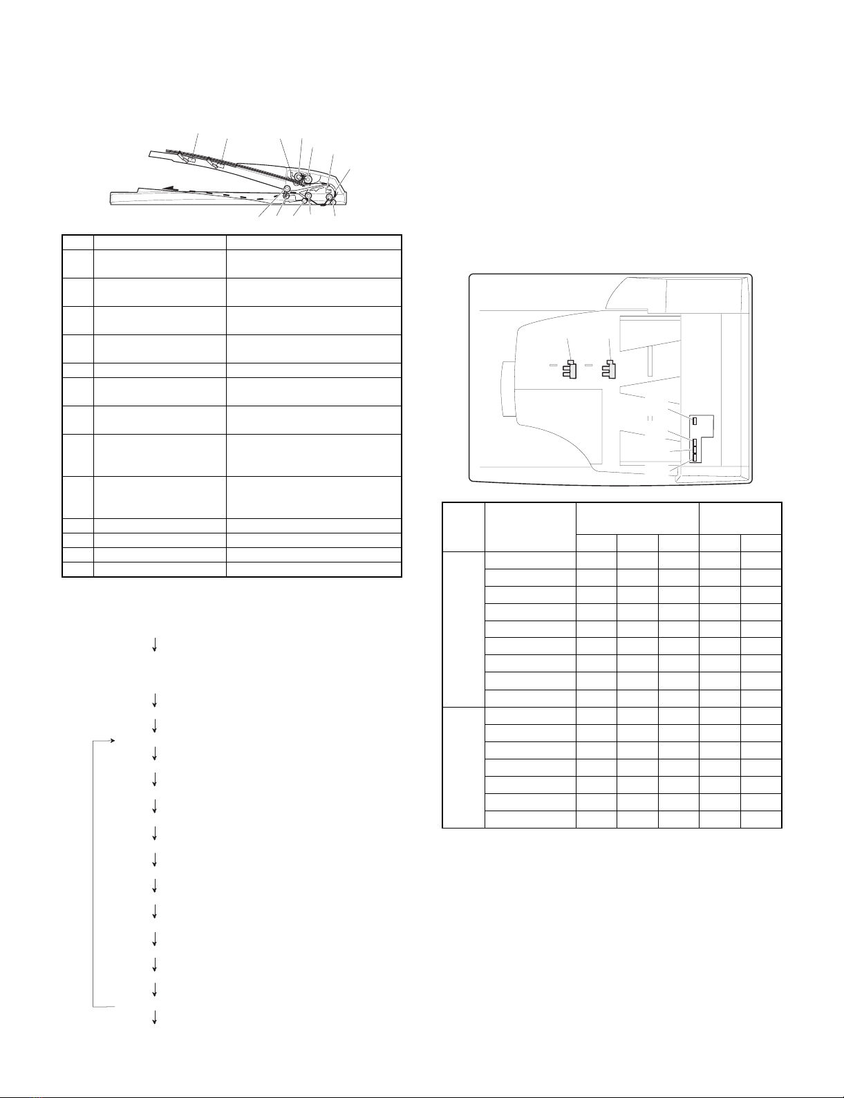
3. Document size detection
Document size detection by document set tray
When a document is set on the document set tray in the auto mode of
paper/copy magnification ratio selection, the document size is
detected to perform the auto selection function of paper and the copy
magnification ratio according to the detected document size.
When documents of different sizes are mixed and set on the tray, the
max. size is detected. The document width is detected by the docu-
ment width sensors (W1, W2, W3), and the document length is
detected by the document length sensors (L1, L2) to determine the
document size.
The document size judgment is made after a certain time from when
the document set sensor (W0) detects the document.
Document size
and set direction
Document width
sensor Document
length sensor
W1 W2 W3 L1 L2
AB
series
A5 FDDDD
B5 FFDDD
A5R DDDDD
A4 FFFDD
B5R DDDFD
A4R FDDFD
8.5" ×13" FDDFF
B4 FDDFF
A3 FFFFF
Inch
series
8.5" ×5.5" FDDDD
8.5" ×5.5"R DDDDD
11" ×8.5" FFFDD
11" ×8.5"R FDDFD
8.5" ×13" FDDFF
8.5" ×14" FDDFF
11" ×17" FFFFF
[Note] Sensor ON: FOFF: D
123,4 56
8
9
1011
12
13
7
1) Document set (Document set sensor ON)
3) Copy start (Machine)
4) SPF motor ON
5) Pickup solenoid ON
6) Pickup roller rotation
7) Paper feed roller rotation
8) Paper entry sensor detects paper presence.
9) PS roller rotation
10) Copy operation (Machine)
11) Transport roller rotation
12) Paper exit roller rotation
13) Document exit
YES
14) Next document
NO
2) Document size detection (The document width is detected
with document width sensors W1, W2, and W3, and the
document length is detected with document length sensors
L1 and L2.)
15) SPF motor OFF
L2 L1
W1
W0
W2
W3
– 5 –

[6] DISASSEMBLY AND ASSEMBLY
1. External fitting section
NOTE: Remove the pawl in the arrow direction.
2. Paper feed unit section
1) Paper feed unit
2) Document transport section cover
3) Document feed section cover
4) Sensor PWB
2
1
2
2
1
1
1
12
1
2
3
2
1
1
1
2
3
4
3
– 6 –

5) Pickup solenoid
NOTE: Remove section A of the pickup solenoid from the solenoid
arm groove.
6) Clutch gear ass’y
7) Pickup roller ass’y
NOTE: When setting the pickup roller ass’y 4, check that rib A is on
the solenoid arm rib.
8) Pickup roller, paper feed roller
A
1
2
1
5
2
4
3
6
6
1
4
2
3
A
1
2
3
1
1
4
– 7 –

3. Interface PWB
4. Document tray section
1) Document tray
2) Rack cover
3) Document length detection SW
5. Drive frame section
1) Drive frame unit
2
1
1
1
2
1
3
2
1
2
1
12
1
2
1
1
– 8 –

2) Transport belt
3) Drive frame ass’y and drive belt
4) SPF motor
6. Transport section
1) Clutch
NOTE: When assembling, check that the rib is in the clutch groove
A, and fix the E-ring.
2) Transport roller gear
1
1
2
3
1
23
1
2
3
A
1
1
1
– 9 –

3) Transport roller
4) PS roller
5) Book sensor
6) Paper feed paper guide upper
NOTE: When assembling, check that the paper feed paper guide
upper is set to rib A and boss B.
7) Paper feed paper guide lower
8) Paper exit roller
1
1
2
1
1
1
A
2
B
3
1
2
2
1
1
– 10 –

[7] MAINTENANCE
1. Maintenance parts
No. Name Work item When
service call Remark
(1) Pickup roller Cleaning F
(2) Separation pad Cleaning F
(3) Paper feed roller Cleaning F
(4) PS roller Cleaning F
(5) Transport roller Cleaning F
(6) Paper exit roller Cleaning F
[Note] When performing maintenance, refer to [6] DISASSEMBLY
AND ASSEMBLY.
1
2
3
4
5
6
– 11 –

[8] ELECTRICAL SECTION
8 7 6 5 4 32 1
A
B
C
D
12345678
D
C
B
A
Senser PWB
PSOL
COVER
L2
RSOL
W3
PAPER 5V2
W1
CLH
MOT
W0
L1
W2
GSOL
RSPF ONLY
5V2
5V2
5V2
SENSER
SOL./CLU.
24V
24V
24V
24V
24V
IC002
IC001
IC003
24V
24V
MOTA
MOTAN
MOTB
MOTBN
SELA
SELB
SELB
Y
5V1
PAPER
COVER
PDOWN
5
CLH
RSOL
PSOL
GSOL
PDOWN
4
A
A/
B
B/
INTERFACE PWB
5V1 24V
RSPF ONLY
5V2
3
4
SPF/RSPF UNIT
1. BLOCK DIAGRAM
Copier body
Data selector
Driver array
Motor driver
1/1
COVER OPEN
– 12 –

8 7 6 5 4 32 1
A
B
C
D
12345678
D
C
B
A
9
24V
SELC
14
24V
COVER OPEN
PPC
GY
BR
Senser PWB
5
17
2
2
PHNR-7-H
PSOL/
PSOL
DF3-3S-2C
LEDSPPD
24V1 5
GSOL/
RD
OR
PK
6
23
Y
15
4
PAPER
RD
BL
COVER
5V2
2
L2
5
6
PHNR-6-H
PHNR-2-H
5
RSOL
B/
1
GY
PK
SMP-02V(N)
3
20
COVER
24
3
PGND
PL
W3
1
1
6
3
1
PAPER FEED UNIT
24V1
CN003
GY
PL
SMP-02V(B)
CL211-0211-6
17
LGND
10
MOTAN
PK
6
13
LGND
25V
RSOL/ 1
3
OR
BL
BL
EARTH
PLATE
6
14
MOTA
MOTBN
5
CLH
5V1
CN001
PL 3
9
LGND
LGND BU6P-TR-P-H
W1
PAPER
CLH/ 1
RD
PL PL
11
GSOL
5V2
16
PSOL
SELA
SRA-21T-4
GY
(PHDR-22VS)
LGND
LGND
20
LGND
PSOL/
1
PAPER
RD
PL
LB
8
24V
SELB
18
9
PDOWN
OR
BR
5V
4
21
1
3
PHNR-7-H
24V1
(PHR-7)
22
A/ 4
24V1
(PHR-2)
OR
PL
5
22
COVER OPEN
13
2
LGND
LB
W1
W0
1
3
6
5
PHNR-2-H
CLH
B
GY
LB
SMR-02V(N)
2
19
PAPER
22
12
PGND
BL
LGND
7
5V2
5
BU7P-TR-P-H
2
2
14
CLH/
5
GY
LB
PHR-3
24V1
16
PGND
8
MOTB
BR 5
W1
5V
5V2
1W0
BU2P-TR-P-H
24V1 2
4
OR
LB LB
SPF FIXING
PLATE
3
13
CLH
23
RSOL
SELC
Interface PWB
PL
2
11
5V
4
2
W2
2
3
6
MOT
RD
PK PK
INTERNAL SPF/DSPF
7
10
PSOL
5V1
20
24V
Y
FG
GY
CN002
19
6
3
3
1
24V1
DF3-3S-2C
LGND
6
RD
OR
BL
7
24
MOTAN
SELA
17
7
COVER
OR
BL
W0
3
L1
4
PHNR-6-H
Original Tray
CN101
18
A
1
2
CN004
GY
PL
PHR-6
4
21
PDOWN
19
1
LGND
LB
W2
COVER
2
7
4
RSOL/
(PHR-7)
GSOL
GY
BR
SMR-02V(B)
1
18
LGND
11
MOTBN
BR 7
16
L1
4
1
8
24V1
1
GY
BL
LB
3
2
15
MOTB
PGND
6
MOTA
5V2
(PHDR-24VS)
PL 4W2
L1
L2
7COVER
24V1 2
RSPF ONLY
OR
BR BR
2
12
RSOL
21
GSOL
SELB
FG
GY
1
W3
L2
15
1
W3
10
2
12
RD
BL BL
N.C.
25 N.C.
BR
(PHR-3)
CN005
1 COVER OPEN
35V2
2LGND
COVER OPEN
1
3
DF3-3S-2C
GP1A71A1 2
RD
OR
BR
GY
2. ACTUAL WIRING DIAGRAM 1/1
– 13 –

8 7 6 5 4 32 1
A
B
C
D
12345678
D
C
B
A
R005
9.1KJ
C003
100000pF
R003
1.5KJ
C005
470pF
R002
1.5J(1W)
C007
2200pF
R001
1.5J(1W)
R008
47kJ
R006
2.4kJ
R009
47kJ
R007
2.4kJ C008
2200pF
C010C011C012 C013C009
C014
2200pFx6
C006
470pF C004
0.1uF
R004 220J(1/4W)
IC001
74HC151
D0
4D1
3D2
2D3
1D4
15 D5
14 D6
13 D7
12
A
11 B
10 C
9G
7
W6
Y5
CN002-9 W2
CN002-13 W1
W3
CN002-11
CN002-7 W0(Document Size Senser)
CN002-15 L1
CN002-17 L2
CN002-18
CN002-16 CN001-10
COVER CN001-8
PAPER
R010
CN003-3
A
CN003-4
A/
CN003-1
B
CN003-2
B/
CN001-3
Y
CN001-2
SELB
CN001-1
SELA
CN001-20
MOTAN CN001-18
MOTA
CN001-14
MOTB
SLA7027M
OUTB 11
TdB
13
RSA
9
OUTA 1
TdA
2
REFA
3
GA
4INA 5
OUTA 8
INA 6
REFB
14
GB
15
OUTB 18
VSA 7
RSB
10
INB 16
VSB 12
INB 17
CN001-16
MOTBN
C001
47uF/35V
+
CN002-2
PSOL/ CN002-6
CLH/ CN002-8
RSOL/
CN001-19 PSOL
CN001-17 CLH
CN001-15 RSOL
CN001-13 GSOL
CN001-11 PDOWN
CN001-7 5V1
CN001-5 LGND
CN001-6 LGND
CN001-22 24V
CN001-24 24V
CN001-21 PGND
CN001-23 PGND
CN002-1
CN002-3
CN002-4
CN002-5
LEDSPPD
CN002-19
LGND
CN002-20
CN002-21
CN002-22
CN002-10
24V1
CN002-12
CN002-14
CN003-5
CN003-6
CN004-1
C002
10uF/16V
+
C015 C016
CN001-4
SELC
C017
2200pFx3
D004
D006
1SS133x3
D002 D003
D007
1SS133
D001
1SS133x3
DSPF
TO 5V1
CN001-9 5V2
C018
10uF/16V
+
IC003
BA12003B
COM 9
I1
1I2
2I3
3I4
4I5
5I6
6I7
7GND
8
O1 16
O2 15
O3 14
O4 13
O5 12
O6 11
O7 10
CN004-2
GSOL/
R016
10kJ
R011
D005
R012 R015
R014
R013
D008
1SS133
CN005-2
CN005-1 CN001-12
COVER OPEN
CN005-3
LED POWER
5V1
24V1
5V1
24V1
5V1
5V1
5V1
74HC151AP
8
16
IC002
IC001
CN001 CN002
CN003
12
34
56
78
910
CLH
PSOL
SELA
Y
LGND
5V1
5V2
PDOWN
GSOL
RSOL
CN004
11
13
15
17
19
21
23
12
14
16
18
20
22
24
SELB
SELC
LGND
PAPER
COVER
MOTB
MOTBN
MOTA
MOTAN
24V
PGND
PGND 24V
ICP001
ICP-N38
(PHDR-22VS)
(PHDR-24VS)
1
3
5
7
9
11
13
15
17
21
5V2
LEDSPPD
W0
W2
W3
W1
L1
L2
LGND
LGND
2
4
6
8
10
12
14
16
18
20
22
PSOL/
5V2
CLH/
RSOL/
24V1
24V1
24V1
COVER
PAPER
LGND
LGND
19
(PHR-2)
(PHR-6)
1
2
3
4
5
6
B
B/
A
A/
24V1
24V1
1
2
24V1
GSOL/
5V2
Senser
MATRIX
L
L
L
L
LL
HL
W1
W2
W3
LH
HH
W0
L1
L
H
H
H
H
L
L
H
HH
L
HL2
SPF/ /RSPF
L
SELA
SELB
SELC Y
CN001
(PHDR-24VS)
CN003
(PHR-7)
CN004
(PHR-2)
CN002
(PHDR-22VS)
PARTS VIEW
7N.C.
COVER OPEN
CN005
(PHR-3)
1
2LED POWER
COVER OPEN
3LGND
CN005
(PHR-3)
5V1
3. CIRCUIT DIAGRAM
1. INTERFACE PWB
1/1
– 14 –

8 7 6 5 4 32 1
A
B
C
D
12345678
D
C
B
A
PT103
GP1S58V
PT101
GP1S58V
PT102
GP1S58V
PT105
GP1S58V
CN101-7 SGND
CN102-2 5V
C101
22000pF
R103
240J/ 1/4W
R102
120J/ 1/4W
CN101-6
COVER
CN101-1
W0
R101
120J/ 1/4W
CN101-5
W3
CN101-4
W2
CN101-3
W1
PT104
GP1S58V
1
2
3
4
5
6
7
W0
5V
W1
W2
W3
COVER
SGND
CN101
(PHR-7)
2. SENSOR PWB
1/1
– 15 –

4. PARTS ARRANGEMENT
[PARTS SURFACE]
[SOLDER SURFACE]
CN001
CN002
1
23
45
67
89
10
CLH
PSOL
SELA
Y
LGND
5V1
5V2
PDOWN
GSOL
RSOL
11
13
15
17
19
21
23
12
14
16
18
20
22
24
SELB
SELC
LGND
PAPER
COVER
MOTB
MOTBN
MOTA
MOTAN
24V PGND
PGND
24V
(PHDR-22VS)
(PHDR-24VS)
1
3
5
7
9
11
13
15
17
21
5V2
LEDSPPD
W0
W2
W3
W1
L1
L2
LGND
LGND
2
4
6
8
10
12
14
16
18
20
22
PSOL/
5V2
CLH/
RSOL/
24V1
24V1
24V1
COVER
PAPER
LGND
LGND
19
1
2
3
4
5
6
B
B/
A
A/
24V1
24V1
1
224V1
GSOL/
5V2
7N.C.
COVER OPEN
CN005
(PHR-3) 1
2
LED POWER
COVER OPEN
3
LGND
CN004
(PHR-2)
CN003
(PHR-6)
– 16 –


ADVARSEL !
Lithiumbatteri – Eksplosionsfare ved fejlagtig håndtering.
Udskiftning må kun ske med batteri
af samme fabrikat og type.
Levér det brugte batteri tilbage til leverandoren.
Caution !
Danger of explosion if battery is incorrectly replaced.
Replace only with the same or equivalent type
recommended by the manufacturer.
“BATTERY DISPOSAL”
CONTAINS MANGANESE DIOXIDE LITHIUM BATTERY
MUST BE DISPOSED OF PROPERLY.
REMOVE THE BATTERY FROM THE PRODUCT AND
CONTACT FEDERAL OR STATE ENVIRONMENTAL
AGENCIES FOR INFORMATION ON RECYCLING
AND DISPOSAL OPTIONS.
VAROITUS
Paristo voi räjähtää, jos se on virheellisesti asennettu.
Vaihda paristo ainoastaan laitevalmistajan suosittelemaan
tyyppiin. Hävitä käytetty paristo valmistajan ohjeiden
mukaisesti.
ATTENTION
Il y a danger d’explosion s’ il y a remplacement incorrect
de la batterie. Remplacer uniquement avec une batterie du
même type ou d’un type équivalent recommandé par
le constructeur.
Mettre au rebut les batteries usagées conformément aux
instructions du fabricant.
VARNING
Explosionsfara vid felaktigt batteribyte.
Använd samma batterityp eller en ekvivalent
typ som rekommenderas av apparattillverkaren.
Kassera använt batteri enligt fabrikantens
instruktion.
Achtung
Explosionsgefahr bei Verwendung inkorrekter Batterien.
Als Ersatzbatterien dürfen nur Batterien vom gleichen Typ oder
vom Hersteller empfohlene Batterien verwendet werden.
Entsorgung der gebrauchten Batterien nur nach den vom
Hersteller angegebenen Anweisungen.
CAUTION FOR BATTERY REPLACEMENT
(Danish)
(English)
(Finnish)
(French)
(Swedish)
(German)

SHARP CORPORATION
Digital Document Systems Group
Quality & Reliability Control Center
Yamatokoriyama, Nara 639-1186, Japan
2000 November Printed in Japan
All rights reserved.
Printed in Japan.
No part of this publication may be reproduced,
stored in a retrieval system, or transmitted,
in any form or by any means,
electronic; mechanical; photocopying; recording or otherwise
without prior written permission of the publisher.
Table of contents
Other Sharp Printer Accessories manuals

Sharp
Sharp AR-NB2 User manual

Sharp
Sharp ARNC5J User manual

Sharp
Sharp FO-59A4 Instruction Manual

Sharp
Sharp ARFX13 - Fax Interface Card User manual

Sharp
Sharp AR-NS1 User manual

Sharp
Sharp AR-FN7 User manual

Sharp
Sharp MX-M260 User manual

Sharp
Sharp MX-LCX2 User manual

Sharp
Sharp AR-DU3 User manual

Sharp
Sharp AR-PB8 User manual
Popular Printer Accessories manuals by other brands

Star Micronics
Star Micronics TSP800 Series install guide

Citizen
Citizen CBM-202PC Series user manual

Canon
Canon Color imageCLASS MF8170c installation instructions

Codonics
Codonics Virtua 1VCX-LR833 Technical brief

Roland
Roland DU2-64 Supplementary manual

TonerRefillKits
TonerRefillKits ReChargX RX126 instructions