Shuttle AK32E User manual

AK32E
SocketA
AMD Athlon/Duron Processor
Based DDR/SDR Main Board
User's Manual

Shuttle®AK32E
SocketA
AMD Athlon/Duron Processor
based DDR/SDR Mainboard
Manual Version 1.0
Copyright
Copyright©2003 by Shuttle®Inc. All Rights Reserved.
This publication, including all photos, illustrations, and software, is protected under interna-
tional copyright laws, with all rights reserved. Reproducing any of the material contained
herein is prohibited without the consent of the publisher.
Disclaimer
Shuttle®Inc. shall not be liable for any incidental or consequential damages resulting from the
performance or use of this product.
This company makes no representations or warranties regarding the contents of this manual.
Information in this manual has been carefully checked for reliability; however, no guarantee is
given as to the correctness of the contents. In the interest of continued product improvement,
this company reserves the right to revise the manual or include changes in the specifications
of the product described within it at any time without notice and without obligation to notify any
person of such revision or changes. The information contained in this manual is provided for
general use by the customers.
Trademarks
Shuttle is a registered trademark of Shuttle Inc.
VIA isaregisteredtrademarkofVIACorporation.
AMD,Athlon/DuronareregisteredtrademarksofAMDCorporation.
PS/2 is a registered trademark of IBM Corporation.
AWARD is a registered trademark of Award Software Inc.
Microsoft and Windows are registered trademarks of Microsoft Corporation.
General Notice: Other product names used in this manual are ascribed to their respective
owners and acknowledged.
M738

Statement of Shuttle Mainboard via the EMI Test
Shuttle mainboards have been via the EMI test in terms of series of regulations: EN55022/
CISPR22/AS/NZS3548ClassB,EN55024 (1998/AS/NZS), EN4252.1 (1994), EN61000,ANSI
C63.4 (1992), CFR47 Part 15 Subpart B, and CNS13438 (1997). The items tested are illus-
trated as follows:
(A)Voltage:AC110V/60HZ &AC230V/50HZ
(B) Tested Product Information:
Product Name: PC Mainboard
Status: Sample
ModelName:AK32E
S/N:N/A
CPU:
External Frequency: 133 MHz
AMDAthlon XP1500+/1600+/1700+/1800+/1900+/2000+/2100+/2200+/2400+/
2600+,1.00/1.13/1.20/1.33/1.40GHz
External Frequency: 100 MHz
AMDAthlon750/800/850/900/950MHz,1.0/1.10/1.20/1.30/1.40GHz
AMDDuron700/750/800/850/900/950MHz,1.0/1.1/1.2/1.3 GHz
Keyboard Port: one port with 6 pins
Mouse Port: one port with 6 pins
USB 2.0 Port: two ports with 4 pins respectively
Parallel Port: one port with 25 pins
Serial Port: two ports with 9 pins respectively
MIDI/Game Port: one port with 15 pins
Line-Out & Line-In & Mic-In Ports: one port for each
DDR Memory: 256 MB *2
All CPUs have completely been tested, and values offered by the worst EMI combination of
CPU external frequency are listed as follows:
(C) Remedy for the Tested Product & Its EMI Interference:
Remedy:N/A
EMIInterference:
Crystal:32.768KHz(X1)/14.318 MHz(X2)/24.576 MHz(X3)
Clock Generator: U10
(D) Difference betweenAK32E and AK32:
To discriminate AK32E from AK32 lies in the extent that chips in AK32E support USB 2.0, and
the combination for testing is based onAK32E.

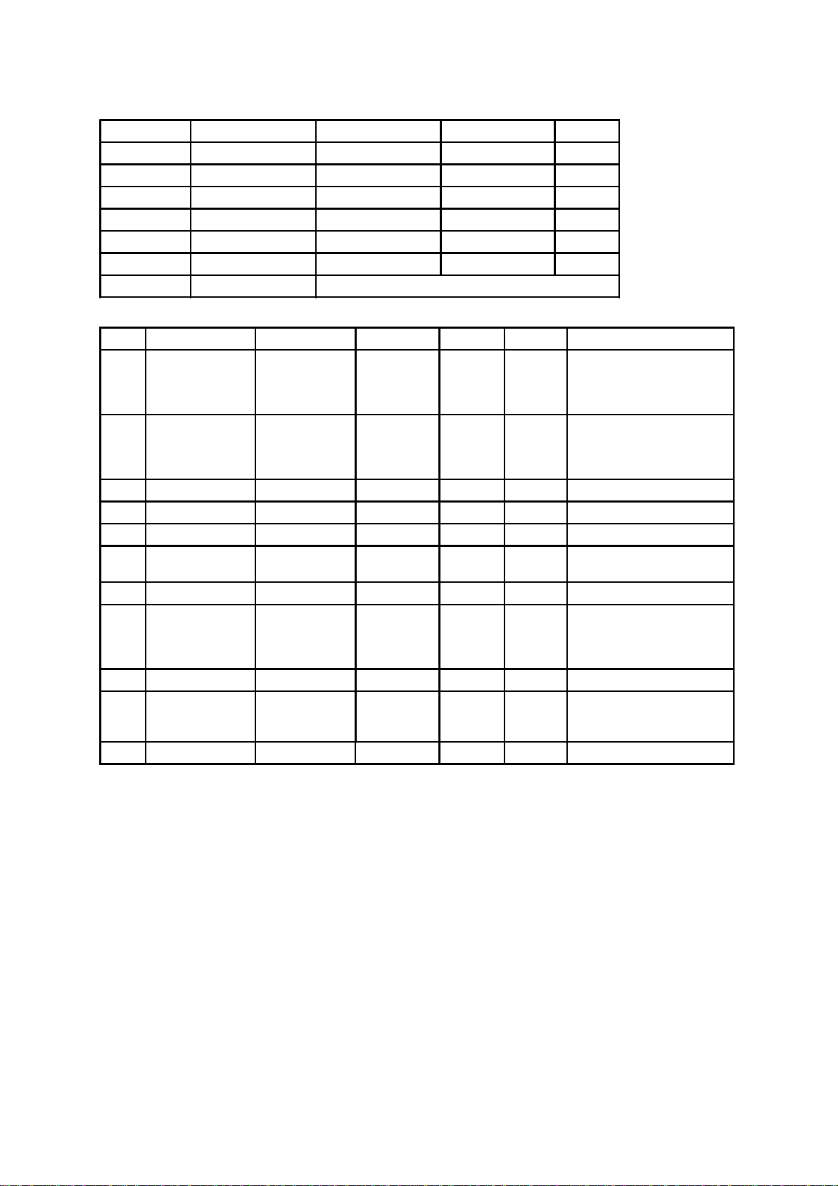
(E) Supported Host Peripherals:
(F) Supported Devices:
(G) Notices for Assembling Computers:
1. Cases should be made of iron or other metal that has good electric conductivity.
2. Cylinders in a case should be made of metal, and as having a mainboard mounted
in a case, make sure screws are all utilized and fastened on a mainboard.
3. An I/O shielding should be contacted with I/O metallic parts of a mainboard.
4. Cables should appropriately be arranged and fixed in a case. Follow instructions:
Ø Leave IDE cables not crossed upon CPU and SDRAM;
Ø Leave power cables minimum in length, and not crossed upon a mainboard;
Ø Leave CPU fan cables minimum in length, and not near CPU;
Ø Leave cables on panels and other spare cables tied in a computer case.
5. Make sure an EMI shielding attached to a case has properly been installed.
6. Make sure a 5.25" or 3.5" FDD and screws are fastened to an EMI shielding.
7. Make sure a case is closely in contact with EMI connected points.
8. Make sure there is no cleft in a case which is not deformed.
9. Make sure a PCI orAGP door is bound to a case.
10. Make sure cables of other devices (fans or some others) are fixed in a case.
Host Peripheral Product Name Model Name S/N FCC ID
#1 Case KF45A N/A
#2 Power Supply (300W) ENP-0730 (ATX12V) 100002885
#3 IBM HDD (30.7GB) 91024UB YKFY7981 3892I168
#4 MITSUMI FDD D353M
#5 ASUS VCD Player CD-S500/A 0524CIH4113070-2
#6 AGP Card Winfast Geforce 2 MX 3892C520
#7 Power Cable Detachable and Shielded
Device Product Name Model Name S/N FCC ID BSMI ID Other Description
#1 Acer Router Router 904 N/A 3902B360
with a 2-Pin AC Converter
(Model Name: AA-091A, and
a Power Cable (w/o a GND
Pin) Detachable and Shielded
#2 Twinhead Portable
USB 2.0 CD-R/RW TEAC CD-W24E N/A 71001020
with a Delta AC Converter
(Model Name: ADP-12NB),
and a 3-Pin Power Cable
Detachable and Shielded
#3 Microsoft Rocker 90873 02132661 3862A202 w/o a Power Cable
#4 Firstline Earphone H1160.0 N/A w/o a Power Cable
#5 KOKA Microphone DM-510 N/A w/o a Power Cable
#6 Acer USB
Amplifier 90.38H12.001 401677 with a Power Cable supplied
by a PC USB Port
#7 Coson Walkman C-2087 N/A w/o a Power Cable
#8 HP Printer C2642A TH84T1N3J3 3872H155
with an HP AC Adapter
(Model Name: C2175A), and
a Power Cable Detachable
and Shielded
#9 Acer Mouse M-S42 LZE93852045 4862A094 w/o a Power Cable
#10 Acer Monitor G781 9990071012
14400445T7
AA31T 42002003 with a Power Cable
Detachable and Shielded
#11 Acer Keyboard 6511-TW4C N/A 4862A064 w/o a Power Cable

- 1 -
WHAT'S IN THE MANUAL..................................................................... 5
Quick Reference............................................................................................... 5
About This Manual ........................................................................................... 5
1 INTRODUCTION................................................................................ 6
1.1 TO DIFFERENT USERS ............................................................................. 6
First-TimeDIY System Builder ................................................................. 6
ExperiencedDIYUser ............................................................................. 6
SystemIntegrator..................................................................................... 6
1.2 ITEM CHECKLIST....................................................................................... 7
2 FEATURES ........................................................................................ 8
2.1 SPECIFICATIONS ....................................................................................... 8
3 HARDWARE INSTALLATION.......................................................... 11
3.1 STEP-BY-STEP INSTALLATION................................................................11
STEP1 Installthe CPU.......................................................................... 12
STEP 2 Set Jumpers............................................................................. 13
STEP3 Install SDRAMSystem Memory ................................................ 13
STEP 4Install InternalPeripherals inSystemCase ................................ 14
STEP5 Mountthe Mainboardon theComputer Chassis........................ 15
STEP6 ConnectFront-panel Switches/LEDs/Speaker/USB.................. 16
STEP 7 Connect IDE & Floppy Disk Drives ........................................... 18
STEP8Connect Other InternalPeripherals............................................ 18
STEP9 ConnectPowerSupply ............................................................. 19
STEP10 InstallAdd-on Cards inExpansion Slots .................................. 19
STEP11 ConnectExternal Peripheralsto Back-panel ........................... 20
STEP 12 First Time System Boot Up ..................................................... 22
STEP13 InstallDriver &Software Components..................................... 23
TABLE OF CONTENTS

- 2 -
3.2 JUMPER SETTINGS ................................................................................. 24
JUMPER& CONNECTOR GUIDE......................................................... 25
Jumpers
Clear CMOS (JP16) .............................................................................. 28
BIOSWriteProtection (JP3) .................................................................. 29
Back-Panel Connectors
PS/2Keyboard & PS/2 Mouse Connectors............................................ 30
USB1/USB2Port Connectors................................................................ 30
COM1/2Connector................................................................................ 30
ParallelPortConnector.......................................................................... 30
Line-Out ................................................................................................ 31
Line-In ................................................................................................... 31
Mic-In..................................................................................................... 31
MIDI/GAMEPort .................................................................................... 31
Front-Panel Connectors
ATXPower On/Off SwitchConnector (PWRPT) .................................... 32
EPMIConnector(EPMI)......................................................................... 32
GreenLED Connector (GLED) .............................................................. 33
HDD LED Connector (HLED) ................................................................ 33
PWR LED Connector (PLED)................................................................ 33
HardwareResetConnector (RST) ......................................................... 34
SpeakerConnector (SPEAKER) ........................................................... 34
ExtendedUSB Header (JP4/JP5).......................................................... 35
Internal Peripherals Connectors
EnhancedIDEPorts andFloppyConnectors ......................................... 36
Other Connectors
ATXPower SupplyConnector (JP6) ...................................................... 37
CoolingFAN Connectors for CPU FANs(FAN1), AGP (FAN2),SYSTEM

- 3 -
(FAN3),or NorthBridge Fan (FAN4) ...................................................... 38
SIR/CIRConnector(JP2) ....................................................................... 39
Wake-On-LANConnector(CN1)............................................................ 39
AudioConnector CD_In(CN2)(Black)................................................... 40
AudioConnectorAUX_In (CN3)(White)................................................. 40
AudioConnectorTAD_In (CN4)(Green) ................................................ 40
3.3 SYSTEM MEMORY CONFIGURATION ..................................................... 41
InstallMemory........................................................................................ 41
UpgradeMemory................................................................................... 41
4 SOFTWARE UTILITY ......................................................................42
4.1 Mainboard CD Overview ......................................................................... 42
4.2 Install VIA 4 in 1 Driver............................................................................. 43
4.3 Install Audio Device Software ................................................................. 44
4.4 Install USB2.0 Driver ............................................................................... 45
4.5 View the User's Manual........................................................................... 46
5 BIOS SETUP ................................................................................... 47
5.1 ENTER THE BIOS..................................................................................... 47
5.2 THE MAIN MENU ...................................................................................... 48
STANDARD CMOS FEATURES ............................................................... 50
ADVANCED BIOS FEATURES................................................................. 54
ADVANCED CHIPSET FEATURES .......................................................... 58
INTEGRATEDPERIPHERALS .................................................................. 62
POWERMANAGEMENT SETUP.............................................................. 66
PNP/PCICONFIGURATION....................................................................... 70
PCHEALTH STATUS................................................................................ 72
FREQUENCY/VOLTAGECONTROL......................................................... 74
LOAD FAIL-SAFE DEFAULTS .................................................................. 75

- 4 -
LOADOPTIMIZEDDEFAULTS ................................................................. 75
SETSUPERVISOR PASSWORD ............................................................. 76
SET USER PASSWORD........................................................................... 76
SAVE & EXIT SETUP................................................................................ 77
EXITWITHOUTSAVING ............................................................................ 77

- 5 -
Quick Reference
Hardware Installation >> Step-by-Step ................................................ Page 11
Jumper Settings >> A Closer Look.......................................................Page 24
Software Utility >> How to Install..........................................................Page 42
BIOS Setup >> How to Configure.........................................................Page 47
About This Manual
For First-Time DIY System Builder.........................................................Page 6
For Experienced DIY User ......................................................................Page 6
For System Integrator .............................................................................Page 6
WHAT'S IN THE MANUAL

- 6 -
1INTRODUCTION
1.1 To Different Users
First-Time DIY System Builder
Welcome to the DIY world! Building your own computer system is not as diffi-
cult as you may think. To make your first computer DIY experience successful,
right from the start, we have designed the Chapter 3 Hardware Installation
section in a step-by-step fashion for all the first-time DIY system builders. Prior
to installation, we also suggest you to read the whole manual carefully to gain a
complete understanding of your new Shuttle AK32E mainboard.
Experienced DIY User
Congratulate on your purchase of the Shuttle AK32E mainboard. You will find
that installing your new Shuttle AK32E mainboard is just easy. Bundled with an
array of onboard functions, the highly-integrated AK32E mainboard provides
you with a total solution to build the most stable and reliable system. Refer to
sections 3.2 Jumper Settings and Chapter 4 Software Utility to find out
how to get the best out of your new mainboard. Chapter 5 BIOS Setup also
contains the relevant information on how to tune up your system to achieve
higher performance.
System Integrator
You have wisely chosen Shuttle AK32E to construct your system. Shuttle AK32E
incorporates all the state-of-the-art technology of the KT266A chipset from VIA.
It integrates the most advanced functions you can find to date in a compact
ATX board. Refer to sections 3.2 Jumper Settings and Chapter 4 Software
Utility for an in-depth view of system construction.

- 7 -
1.2 Item Checklist
Check all items with your AK32E mainboard to make sure nothing is missing.
The complete package should include:
-One piece of Shuttle AK32E Mainboard
-One piece of ATA133/100/66/33 Ribbon Cable
-One piece of Floppy Ribbon Cable
-One piece of twin ports USB2.0 Cable (optional)
-AK32E User's Manual
-One piece of Bundled CD-ROM with containing:
ØAK32E user's manual on PDF format
ØVIA 4-IN-1 driver
ØAudio driver
ØUSB 2.0 driver
ØAward Flashing Utility

- 8 -
AK32E mainboard is carefully designed for the demanding PC user who wants high
performance and maximum intelligent features in a compact package.
2.1 Specifications
-CPU Support
Support Socket462 package CPU with 200/266 MHz FSB.
AMD Athlon Processor: 600 ~ 1.33+GHz. XP2000+...
AMD Duron Processor 600 ~ 850+ MHz. Morgan1200+...
-Chipset
Features VIA KT266A, VT8366A/VT8235 Chipset.
VT8366A, Integrated high performance SDRAM and DDR DRAM controller.
-Jumperless CPU Configuration
Soft-configuration FSB (The FSB speed is software configurable from 100MHz
to 165MHz by 1MHz step in the Frequency/Voltage Control of BIOS setup
program.)
-AC'97 Link for Audio and Telephony CODEC
AC'97 2.1 compliant
Spread independent PCI functions for Audio and Modem
-Versatile Memory Support
Two 184-pin DIMM slots to support up to 2GB of PC1600 or PC2100
compliant DDR SDRAM module.
or two 168-pin DIMM slots to support up to 2GB of PC100 or PC133
compliant SDR SDRAM module.
-PCI Expansion Slots
Provides five 32-bit PCI slots.
-AGP Expansion Slot
Provides one 32-bit AGP slot which supports up to 4X AGP device.
-I/O Interface
Provides a variety of I/O interfaces:
Ø1*Floppy interface for 3.5-inch FDD with 720KB, 1.44MB, or 2.88MB
2 FEATURES

- 9 -
format or for 5.25-inch FDD with 360K or 1.2MB format.
Ø1*PS/2 mouse connector.
Ø1*PS/2 Keyboard connector.
Ø2*DB9 Serial connectors 16550 UART compatible.
Ø1*Infrared communication port .
(Serial port COM2 can also be redirected to an external IrDA Adapter
for wireless connection.)
Ø1*DB25 Parallel port supporting Standard Parallel Port (SPP),
Enhanced Parallel Port (EPP), and Extended Capabilities Port (ECP)
data transmission schemes.
Ø1*Line-Out port.
Ø1*Line-In port.
Ø1*Mic-In port.
Ø1*MIDI/GAME port.
-6 USB1.1/USB2.0 Supported Onboard
Ø2 USB connectors on back-panel and 2 sets of dual USB ports headers on
mid-board.
-PCI Bus Master IDE Controller Onboard
Two UltraDMA 133/100/66/33 Bus Master Dual-channel IDE ports provide
support to a maximum of four IDE devices (one Master and one Slave per chan-
nel). The IDE Bus implements the data transfer speed up to 133/100/66/33
MB/sec and also supports Enhanced PIO Modes 0~4.
80-pin Cable Backward Compatible Legacy ATAPI Devices, ATAPI IDE CD-
ROM, CD-R, CD-RW, and LS-120 Supports.
-ATX Power Supply Connector
ATX power supply unit can be connect to the onboard 20-pin ATX power
connector, supporting Suspend and Soft-On/Off by dual-function power
button.
-Advanced Configuration and Power Interface
Features four power saving modes: Snoop, Suspend to RAM, Suspend to
Disk, and Soft-Off. ACPI provides more efficient Energy Savings Features
controlled by your operating system that supports OS Direct Power Man-
agement (OSPM) functionality.

- 10 -
-System BIOS
Provides licensed Award BIOS V6.0 PG on 2Mb Flash EEPROM and
supports Green PC, Desktop Management Interface (DMI).
-ATX Form Factor
System board conforms to the ATX specification.
Board dimension: 305mm* 244mm.
-Advanced Features
ØDual Function Power Button - The system can be in one of two states;
one is Suspend mode and the other is Soft-Off mode. Pushing the
power button for less than 4 seconds places the system into Suspend
mode. When the power button is pressed for longer than 4 seconds, the
system enters the Soft-Off mode.
ØWake-on-LAN (WOL) - The onboard WOL connector can be attached
to a network card that supports this function to wake up the system via
LAN.
ØModem Ring Power-On - The system can be powered on automatically
by the activation of modem ring.
ØCPU Clock Setting- This item allows users to adjust CPU Host Clock in BIOS.
ØCPU Ratio Setting- This item allows users to adjust CPU Ratio in BIOS.
ØCPU Vcore Setting- This item allows users to adjust CPU Vcore in BIOS.
-Intelligent Features
ØVoltage Monitoring -Monitors various voltages of key elements, such as
the CPU, and other critical system voltage levels to ensure stable current
passing through mainboard components. System voltages include +3.3VIN,
+5V, +12V, -12V, -5V on system etc.
ØFan Status Monitoring - To prevent CPU from overheating, the CPU fan is
monitored for RPM and failure. (CPU Cooling FAN with RPM sensor is
required.)
ØTemperature Monitoring - This item allows users to make sure whether
the CPU or system runs in a suitable temperature.

- 11 -
3HARDWARE INSTALLATION
Before removing or installing any of these devices including CPU, DIMMs,
Add-On Cards, Cables, please make sure to unplug the onboard power
connector.
This section outlines how to install and configure your AK32E mainboard. Refer to the
following mainboard layout to help you identify various jumpers, connectors, slots, and
ports. Then follow these steps to guide you through a quick and correct installation of
your system.
3.1 Step-by-Step Installation
Accessories Of AK32E
KB1
USB1
CON1
AGP_FAN
SYSTEM_FAN
AUDIO1
IDE2
CPU_FAN
NB_FAN
IDE1
FDD
WOL
PCI1
PCI2
PCI3
PCI4
PCI5
IR
USB5&6 USB3&4
P
a
n
a
s
o
n
i
c
C
R
2
0
3
2
3
V
J
A
P
A
N
1
CN4
CN3
CN2
TAD/IO
CD-IN
AUX
AGP1
1
1
1
10 10
1
1
1
1
1
1
1
1
1
JP16
JP2
JP5
JP4
JP3
FAN3
FAN2
FAN1
FAN4
FDD1
IDE2
IDE1
1
1
1
AWARD
PCI/PNP 686
169332966
1998
C
CN1
1
inbond
DIMM1
DIM1
JP6
DIMM2
DIM2
S
O
C
K
E
T
4
6
2
PS/2 Keyboard/Mouse
Connectors
ATX Power Connector
Parallel Connector
Serial Port
Connector (COM2)
Serial Port
Connector (COM1)
Line-In/Line-Out/Mic-In
Game/MIDI Connectors
FloppyConnector
BIOS Write Protection -
JP3
Front Panel Connector -
JP7
TwoE-IDEConnectors
FAN3
FAN1
FAN4
FAN2
Socket462
Five PCI Slots
One 4 X AGP Slot
VIA VT8366A Chipset
VIAVT8235 Chipset
USB Connectors
IR Connector -
JP2
ClearCMOS-JP16
I/O Controller
CD Audio Connectors
Onboard CODEC
Wake-On-LAN Connector - CN1
Programmable 2Mb Flash EEPROM
Extended four USB Connectors
header - JP4/JP5
Two184-pinDDRDIMM Slots
Two168-pinSDRDIMM Slots
PWR1 ATXPWR
JP7 1
RST
Power LED
- +
SPEAKER
GLED
+ -
- +
EPMI
Power
On

- 12 -
Step 1
Install the CPU:
1. Locate the CPU ZIF (Zero Insertion Force) socket on the upper-right
sector of your mainboard (between the back-panel connectors and the
DIMM memory slots).
2. Pull the CPU ZIF socket lever slightly sideways away from the socket
to unlock the lever, and then bring it to an upwardly vertical position.
3. Place your AMD 462 Athlon/Duron processor in the socket A. Note that
the CPU's edges have been purposely designed non-symmetrically to pre-
vent from inserting the processor in the wrong direction. The following
diagram demonstrates the correct placement of the CPU in the ZIF socket.
You can see that the two blunt-edged corners should face towards the
socket-lever.
4. Slightly push the AMD 462 Athlon/Duron processor into the socket without
applying excessive force while making sure there is no gap between CPU
and socket. Then lower the socket-lever all the way down to its horizontal
position and lock it to secure the CPU in place.
5. The AMD 462 Athlon/Duron processor requires a set of heatsink/fan to
ensure proper cooling of the processor. If heatsink/fan have not been
already mounted on your CPU, you must purchase the heatsink/fan sepa-
rately and have it installed. Plug the cable through the heatsink/fan in the
CPU fan power connector located nearby. Note that there are several types
of CPU fan connectors. Normally, if your mainboard supports the hard
ware monitoring function, a 3-pin fan power connector should allow your
system to detect the CPU fan's speed. The CPU fan can also run with a
2- pin fan power connector, however, detection of CPU fan's speed is not
supported. Another type of CPU fan may feature a large 4-pin fan power
connector, which does not support CPU fan's speed detection and must
be directly connected to the system's power supply unit. Please refer to
the following diagram.
Notch
AMD CPU
S
O
C
K
E
T
4
6
2
ASSEMBLED IN MALAYSIA
Lever
Blank
Blank
S
O
C
K
E
T
4
6
2

- 13 -
Step 2.
Set Jumpers
This mainboard is jumperless! The default jumper settings have been set for
the common usage standard of this mainboard. Therefore, you do not need
to reset the jumpers unless you require special adjustments as in any of the
following cases:
1. Clear CMOS
2. BIOS Write Protect
For first-time DIY system builders, we recommend that you do not change the
default jumper settings if you are not totally familiar with mainboard configu-
ration procedures. The factory-set default settings are tuned for optimum
system performance. For the advanced users who wish to customize their
system, section 3.2 Jumper Settings will provide detailed information on how
to configure your mainboard manually.
Step 3.
Install DDR or SDR SDRAM System Memory
To insert memory module(s) in any one or two DIMM slot(s). Please note
that modules are directional and will not go in the DIMM slots unless prop-
erly oriented. After the module is fully inserted into the DIMM slots, lift the
clips of both sides of the DIMM slot to lock the module in place.
SDR SDRAM DDR SDRAM

- 14 -
Step 4
Install Internal Peripherals in System Case
Before you install and connect the mainboard into your system case, we
recommend that you first assemble all the internal peripheral devices into the
computer housing, including but not limited to the hard disk drive (IDE
/HDD), floppy disk drive (FDD), CD-ROM drive, and ATX power supply unit.
This will greatly facilitate in making the connections to the mainboard de-
scribed below.
To install IDE & FDD drives, follow this procedure:
1. Set the required jumpers on board each device according to the
instructions provided by the manufacturer. (IDE devices, HDD, and
CD-ROM have to set jumpers on Master or Slave mode depending
on your willing to install more than one device for each kind.)
2. Connect IDE cable and FDD cable on the back-panel of the internal
peripheral devices to the corresponding headers on board. Note that the
cable should be oriented with its colored stripe (usually in red or magenta)
connected to pin#1 both on the mainboard IDE or FDD connector and on
the device as well.
3. Connect an available power cable through your system power supply unit
to the back-panel of each peripheral device. Note that the power cable
is directional and cannot fit in if it is not properly positioned.

- 15 -
Step 5
Mount the Mainboard on the Computer Chassis
1. You may find that there are a lot of different mounting hole positions both
on your computer chassis and on the mainboard. To choose a correct
mounting hole, the key point is to keep the back-panel of the mainboard
in a close fit with your system case, as shown below.
2. After deciding on the proper mounting holes, position the studs be tween
the frame of chassis and the mainboard. The studs are used to fix the
mainboard and to keep a certain distance between the system chassis and
the mainboard, in order to avoid any electrical shortage between the
board and the metal frame of chassis. (If your computer case is already
equipped with mounting studs, you will need to tighten screws to attach
the mainboard.)
Note:Note:
Note:Note:
Note: Inmost computer housings, you will be able to find 4 or more
attachmentpoints toinstall mounting studs and fixthe mainboard.
If there aren't enough matching holes, then make sure to install at
least 4 mounting studs to ensure proper attachment of the
mainboard.

- 16 -
Step 6
Connect Front-Panel Switches/LEDs/Speaker/USB connectors
You can find there are several different cables already existing in the system
case and originating from the computer's front-panel devices (HDD LED,
Power LED, Reset Switch, PC Speaker, or USB devices etc.) These cables
serve to connect the front-panel switches, LEDs, USB connectors to the
mainboard's front-panel connectors group (JP7, JP4 and JP5), as shown
below.
1. ATX Soft Power On
2. EPMI (Hardware System Management
Interface)
3. Green_LED (GLED)
JP7
1
RST
Power LED
- +
SPEAKER
GLED
+ -
- +
EPMI
Power
ON
HLED
JP7
1
RST
Power LED
- +
SPEAKER
GLED
+ -
- +
EPMI
Power
ON
HLED
JP7
1
RST
Power LED
- +
SPEAKER
GLED
+ -
- +
EPMI
Power
ON
HLED
USB5&6
1
10
USB3&4
10
1
JP4
JP5
JP7
1
RST
Power LED
- +
SPEAKER
GLED
+ -
- +
EPMI
Power
ON
HLED
Table of contents
Other Shuttle Motherboard manuals

Shuttle
Shuttle Spacewalker AV40 User manual

Shuttle
Shuttle Spacewalker AE14 User manual

Shuttle
Shuttle MV43P User manual

Shuttle
Shuttle FN41U User manual

Shuttle
Shuttle HOT-687V User manual

Shuttle
Shuttle HOT-683 User manual

Shuttle
Shuttle FB81 User manual

Shuttle
Shuttle Spacewalker MV17 User manual

Shuttle
Shuttle Spacewalker ME17 User manual

Shuttle
Shuttle AE23 User manual

Shuttle
Shuttle HOT-433 User manual

Shuttle
Shuttle AV64 User manual

Shuttle
Shuttle FB61 User manual

Shuttle
Shuttle AB48 User manual

Shuttle
Shuttle AB60P User manual

Shuttle
Shuttle AB49 User manual

Shuttle
Shuttle Spacewalker MV18 User manual

Shuttle
Shuttle HOT-579 User manual

Shuttle
Shuttle FN41V3 User manual

Shuttle
Shuttle FB65 User manual