Siemens FDM275 Guide
Other Siemens Security System manuals
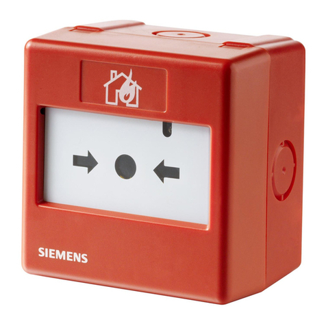
Siemens
Siemens FDM231-RP User manual

Siemens
Siemens 3SX3235 User manual
Siemens
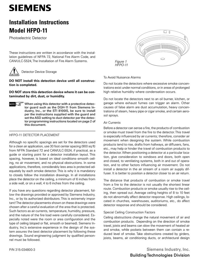
Siemens HFPO-11 User manual
Siemens
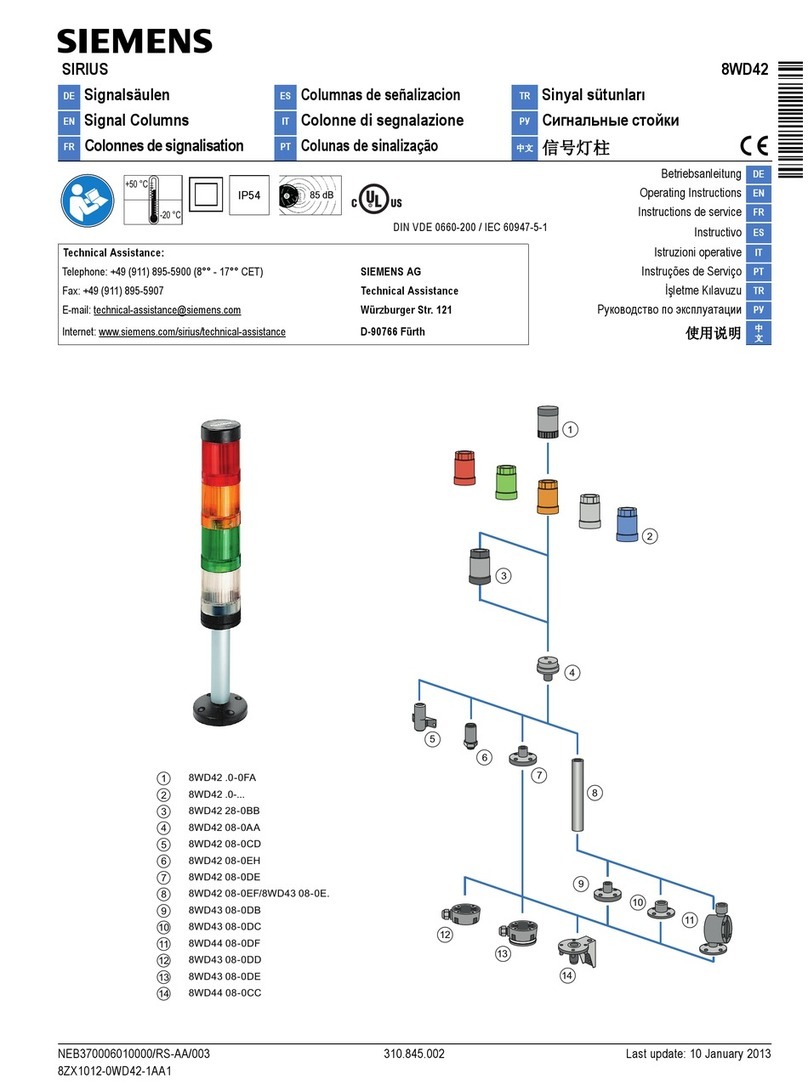
Siemens SIRIUS 8WD42 User manual

Siemens
Siemens Codoor CD3500 Instruction Manual

Siemens
Siemens FDM223-Ex User manual

Siemens
Siemens IMKW6-10 User manual
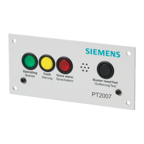
Siemens
Siemens Cerberus PACE User manual

Siemens
Siemens ISRW6-12 User manual
Siemens
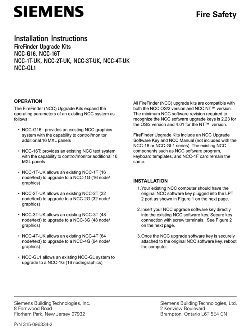
Siemens NCC-G16 User manual

Siemens
Siemens SIPASS SK5 Installation and operation manual
Siemens
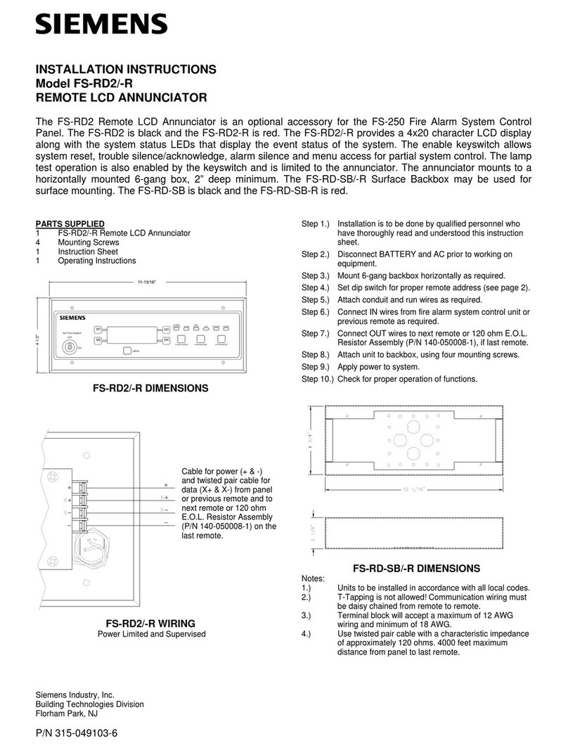
Siemens FS-RD2 User manual
Siemens
Siemens MI291A Guide
Siemens
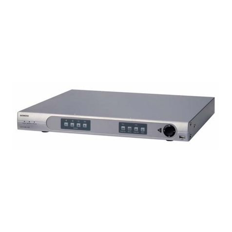
Siemens SISTORE AX4 User manual

Siemens
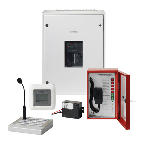
Siemens Cerberus PACE Guide
Siemens
Siemens Cerberus PACE Compact Service manual

Siemens
Siemens SISTORE AX4 User manual

Siemens
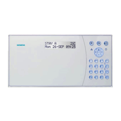
Siemens 3SX3235 User manual
Siemens
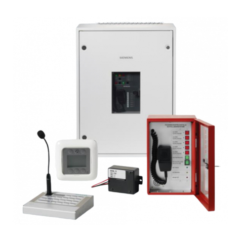
Siemens IC60 User manual
Siemens
Siemens Novigo Core Service manual
Popular Security System manuals by other brands

Inner Range
Inner Range Concept 2000 user manual

Climax
Climax Mobile Lite R32 Installer's guide

FBII
FBII XL-31 Series installation instructions

Johnson Controls
Johnson Controls PENN Connected PC10 Install and Commissioning Guide

Aeotec
Aeotec Siren Gen5 quick start guide

IDEAL
IDEAL Accenta Engineering information

Swann
Swann SW-P-MC2 Specifications

Ecolink
Ecolink Siren+Chime user manual

Digital Monitoring Products
Digital Monitoring Products XR150 user guide

EDM
EDM Solution 6+6 Wireless-AE installation manual

Siren
Siren LED GSM operating manual

Detection Systems
Detection Systems 7090i Installation and programming manual

