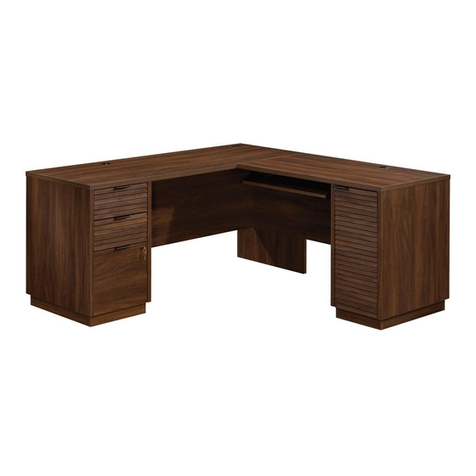
manuals.online logo
Brands
  1. Home
  2. •
  3. Brands
  4. •
  5. Teknik
  6. •
  7. Indoor Furnishing
  8. •
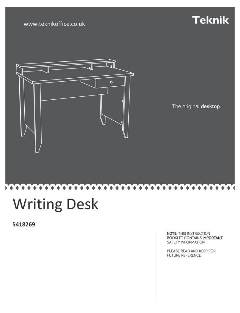
  9. Teknik 5422379 User manual

Teknik 5422379 User manual

www.teknikoffice.co.uk
Sit-Stand Desk
Model 5422379
For all your
newfangled gadgetry.
Teknik
Table of Contents Assembly Tools Required
2-3
4-5
6-38
39-43
44-48
49-50
51
Part Identification
Hardware Identification
Assembly Steps
Français
Español
Safety
Warranty
Hammer
Not actual size
No. 2 Phillips Screwdriver
Tip Shown Actual Size
Skip the power trip.
This time.
Page 2
Part Identification
åWhile not all parts are labeled, some of the parts will have a label or an inked letter on the edge
to help distinguish similar parts from each other. Use this part identification to help identify similar parts.
A RIGHT END (1)
B LEFT END (1)
C PEDESTAL RIGHT END (1)
D PEDESTAL LEFT END (1)
D14 LARGE RIGHT DRAWER SIDE (1)
D15 LARGE LEFT DRAWER SIDE (1)
D20 SMALL RIGHT DRAWER SIDE (1)
D21 SMALL LEFT DRAWER SIDE (1)
D74 SMALL DRAWER BACK (1)
D78 LARGE DRAWER BACK (1)
D716 DRAWER BOTTOM (2)
E TOP (1)
F LIFT-TOP (1)
G UPRIGHT (1)
H LARGE BOTTOM (1)
I BACK STRETCHER (1)
J STRETCHER (1)
K BACK (1)
L SMALL BACK (1)
M2 FRONT (1)
N SHELF (1)
O FRONT LEG (1)
P LEFT FRONT LEG (1)
Q RIGHT FRONT LEG (1)
R REAR LEG (1)
S LEFT REAR LEG (1)
T RIGHT REAR LEG (1)
U PEDESTAL BOTTOM (1)
V PEDESTAL BACK (1)
W LARGE DRAWER FRONT (1)
X LIFT-TOP STRETCHER (1)
Y2 SMALL DRAWER FRONT (1)
Z BOTTOM MOLDING (1)
AA SMALL UPRIGHT (1)
Part Identification Now you know
our ABCs.
Page 3
A
B
C
D
E
F
G
H
I
J
K
L
M2
N
O
P
Q
R
T
S
U
V
W
X
Y2
Z
AA
D20
D716
D21
D74
D14
D716
D15
D78
Hardware Identification
åScrews are shown actual size. You may receive extra hardware with your unit.
Page 4
FILE GLIDE - 2
4B
LONG PULL - 2
21K
40CA CABINET RIGHT - 1 40CB CABINET LEFT - 1 40CC DRAWER RIGHT - 1 40CD DRAWER LEFT - 1
SUPPORT BRACKET - 2
37G
(EXTENSION SET SHOWN SEPARATED)
EXTENSION RAIL - 2
35MA EXTENSION SLIDE - 2
35MC
PULL - 3
98K
10A SLIDE CAM - 4
HIDDEN CAM - 40
1F 10F TWIST-LOCK®
FASTENER - 22
CAM SCREW - 40
8F WOOD DOWEL - 10
15F
METAL BRACKET - 4
2G ANGLE BRACKET - 2
27G
GLUE - 1
54M
NUT - 8
24M
WASHER - 8
13M
Hardware Identification
åScrews are shown actual size. You may receive extra hardware with your unit.
Page 5
BLACK 9/16" LARGE HEAD SCREW - 32
1S 3S GOLD 5/16" FLAT HEAD SCREW - 16
BLACK 1/2" FLAT HEAD SCREW - 4
11S 15S SILVER 5/8" MACHINE SCREW - 4
30S BLACK 1-9/16" FLAT HEAD SCREW - 8 GOLD 1" MACHINE SCREW - 2
50S
BLACK 3/4" MACHINE SCREW - 4
92S BLACK 1-1/4" MACHINE SCREW - 4
93S
BLACK 1-15/16" FLAT HEAD SCREW - 6
113S
GROMMET - 1
10P
CORD CLIP - 4
9P CAM COVER - 16
13P
141M LIFT TABLE
MECHANISM SET - 1
Step 1
å Assemble your unit on a carpeted floor or on the empty carton
to avoid scratching your unit or the floor.
å To begin assembly, push twenty-two SAUDER TWIST-LOCK®
FASTENERS (10F) into the large holes in the RIGHT END (A),
UPRIGHT (G), LARGE BOTTOM (H), SHELF (N), and
PEDESTAL BOTTOM (U).
Page 6
A
G
H
N
U
(22 used)
10F
Do not tighten the TWIST-LOCK® FASTENERS in this step.
10F
10F
10F
å Push forty HIDDEN CAMS (1F) into the ENDS (A and B),
PEDESTAL ENDS (C and D), UPRIGHT (G), STRETCHERS (I and J),
BACKS (K and L), FRONT (M2), and PEDESTAL BACK (V).
Step 2
Page 7
A
B
C
D
G
I
J
K
L
M2
V
Arrow
The arrow in the HIDDEN
CAM must point toward the
hole in the edge of the board.
Hole
1F
Arrow
Arrow
1F
(40 used)
Some assembly
(and snacks) required.
Step 3
Page 8
D
J
O
P
Q
R
S
T
8F
å Turn forty CAM SCREWS (8F) into the PEDESTAL LEFT
END (D), STRETCHER (J), and LEGS (O, P, Q, R, S, and T).
å NOTE: Be sure to use the exact holes shown.
(40 used) 8F
8F
åFirst, fill the holes in the LEGS (P and S) 1/4 to 1/2 full with
GLUE (54M). Then, insert the WOOD DOWELS (15F) into the
holes. Wipe away the excess GLUE.
åNOTE: Be sure to position the parts exactly as shown.
åNOTE: Use the exact holes shown.
åNow, fill the holes in the LEFT END (B) and STRETCHER (J)
1/4 to 1/2 full with GLUE.
åFasten the LEGS (P and S) to the LEFT END (B) and
STRETCHER (J). Tighten six HIDDEN CAMS.
åNOTE: Be sure the WOOD DOWELS in the LEGS
insert into the LEFT END and STRETCHER.
Wipe away the excess GLUE.
Step 4
Page 9
P
S
Fill the holes 1/4 to 1/2 full with GLUE.
Inspect the parts thoroughly before
assembling. Disassembly of glued
parts is extremely dicult.
Caution
!
54M
15F
B
J
12
These holes
should be here.
The LEGS will
overhang this edge.
15F
15F
15F
Step 5
å Fasten the LEGS (O and R) to the PEDESTAL LEFT END (D)
and UPRIGHT (G). Tighten eight HIDDEN CAMS.
å NOTE: Be sure to position the parts exactly as shown.
Page 10
O
R
D
G
Surface
with
HIDDEN
CAMS
The LEGS will
overhang this edge.
The TWIST-LOCK®
FASTENERS must be here.
This small hole
must be here.
These surfaces
should be even.
å Fasten the LEGS (Q and T) to the RIGHT END (A) and
PEDESTAL RIGHT END (C). Tighten eight HIDDEN CAMS.
å NOTE: Be sure to position the parts exactly as shown.
Step 6
Page 11
Q
T
C
A
The TWIST-LOCK®
FASTENERS must be here.
Surface
with
HIDDEN
CAMS
These surfaces
should be even.
The LEGS will
overhang this edge.
This small hole
must be here.
Step 7
å Fasten the CABINET RIGHT (40CA) to the RIGHT END (A)
and the CABINET LEFT (40CB) to the UPRIGHT (G). Use
four GOLD 5/16" FLAT HEAD SCREWS (3S) through
holes #1 and #3.
Page 12
GOLD 5/16" FLAT HEAD SCREW
(4 used in this step)
3S
1
2
3
4
1
2
34
Roller end
A
G
Roller end
R
T
The REAR LEGS (R and T) will
have CAM SCREWS facing up.
Step 8
Page 13
C
D
R
T
Open end
å Separate the EXTENSION SLIDES (35MC) from the EXTENSION RAILS (35MA) as
shown in the upper diagram below. Be prepared, the parts are greasy.
å Fasten the EXTENSION RAILS (35MA) to the PEDESTAL RIGHT END (C) and PEDESTAL
LEFT END (D). Use four GOLD 5/16" FLAT HEAD SCREWS (3S).
å NOTE: For each EXTENSION RAIL, turn a SCREW into the hole shown in the enlarged
diagram. Then, slide the inner cartridge of the EXTENSION RAIL in to find the other hole
that lines up with the hole in the ENDS. Turn a SCREW into this hole.
å NOTE: The EXTENSION SLIDES will be used later for the large DRAWER.
Open end
GOLD 5/16" FLAT HEAD SCREW
(4 used in this step)
3S
Push the black lever in and pull the SLIDE from the RAIL.
35MA
35MC
Step 9
å Fasten the LARGE BOTTOM (H) to the BACK (K). Tighten
two TWIST-LOCK® FASTENERS.
Page 14
How to use the SAUDER TWIST-LOCK® FASTENER
1. Insert the dowel end of the FASTENER into the
hole of the adjoining part.
NOTE: The dowel end of the FASTENER must
remain fully inserted in the hole of the adjoining
part while locking the FASTENER.
2. Tighten the FASTENER with a Phillips
screwdriver as tight as possible.
Dowel end
Surface with TWIST-LOCK® FASTENERS
H
K
Surface with HIDDEN CAMS
Straight edge
This large hole
must be here.
åFirst, fill the hole in the BACK (K) 1/4 to 1/2 full with GLUE (54M).
Then, insert a WOOD DOWEL (15F) into the hole. Wipe away the
excess GLUE.
åNow, fill the hole in the SMALL UPRIGHT (AA) 1/4 to 1/2 full
with GLUE.
åPlace the SMALL UPRIGHT (AA) onto the WOOD DOWEL in the
BACK (K). Wipe away the excess GLUE.
åFasten the LARGE BOTTOM (H) to the SMALL UPRIGHT (AA).
Use three BLACK 1-15/16" FLAT HEAD SCREWS (113S).
Step 10
422379www.sauder.com/services Page 15
Fill the holes 1/4 to 1/2 full with GLUE.
Inspect the parts thoroughly before
assembling. Disassembly of glued
parts is extremely dicult.
Caution
!
54M
15F
H
AA
K
Surface
without
holes
Short edge
without holes
BLACK 1-15/16" FLAT HEAD SCREW
(3 used in this step)
113S
Step 11
å Insert three CORD CLIPS (9P) into the holes in
the LARGE BOTTOM (H).
å NOTE: The CORD CLIPS are used to manage
your cords.
Page 16
H
NOTE: Use one of these holes
depending on the location of
the outlet. The cords will hang
near the LEFT REAR LEG or
the REAR LEG.
This hole is closer to
the LEFT REAR LEG.
This hole is closer to
the REAR LEG.
9P
9P
Just think. The sooner
you do this, the sooner
you do something else.
å Fasten a PULL (98K) to the FRONT (M2). Use two
SILVER 5/8" MACHINE SCREWS (15S).
å Fasten the FRONT (M2) to the LARGE BOTTOM (H).
Tighten two TWIST-LOCK® FASTENERS.
Step 12
Page 17
H
SILVER 5/8" MACHINE SCREW
(2 used for the PULL)
15S
Curved edge
98K
M2
M2
Step 13
åNOTE: Use the exact holes shown.
åFirst, fill the holes in the STRETCHER (J) and LEGS (P and S) 1/4 to 1/2 full with GLUE (54M). Then, insert the WOOD
DOWELS (15F) into the holes. Wipe away the excess GLUE.
åNow, fill the holes in the BACK (K) and FRONT (M2) 1/4 to 1/2 full with GLUE.
åFasten the BACK (K) and FRONT (M2) to the LEGS (P and S). Tighten four HIDDEN CAMS. Wipe away the excess GLUE.
åNOTE: Be sure the WOOD DOWELS in the LEGS insert into the BACK and FRONT.
åFasten the LARGE BOTTOM (H) to the LEFT END (B). Tighten two TWIST-LOCK® FASTENERS.
åNext, fill the hole in the BACK STRETCHER (I) 1/4 to 1/2 full with GLUE.
åFasten the BACK STRETCHER (I) to the STRETCHER (J). Tighten one HIDDEN CAM. Wipe away the excess GLUE.
åNOTE: Be sure the WOOD DOWEL in the STRETCHER inserts into the BACK STRETCHER.
Fill the holes 1/4 to 1/2 full with GLUE.
Inspect the parts thoroughly before
assembling. Disassembly of glued
parts is extremely dicult.
Caution
!
54M
H
M2
B
J
I
15F
15F
15F
P
S
K
Surface
without
HIDDEN
CAMS
Edge with the
two larger holes.
Page 18
Step 14
åFirst, fill the holes in the BACK (K) and FRONT (M2) 1/4 to 1/2 full with GLUE (54M). Then, insert the WOOD
DOWELS (15F) into the holes. Wipe away the excess GLUE.
åNOTE: Use the exact holes shown.
åNow, fill the holes in the LEGS (O and R) 1/4 to 1/2 full with GLUE.
åFasten the PEDESTAL LEFT END (D) to the BACK STRETCHER (I). Tighten one HIDDEN CAM and use one
BLACK 1-15/16" FLAT HEAD SCREW (113S).
åFasten the LEGS (O and R) to the BACK (K) and FRONT (M2). Tighten four HIDDEN CAMS. Wipe away the
excess GLUE.
åNOTE: Be sure the WOOD DOWELS in the BACK and FRONT insert into the LEGS.
åFasten the UPRIGHT (G) to the LARGE BOTTOM (H). Use two BLACK 1-15/16" FLAT HEAD SCREWS (113S).
15F
H
M2 K
I
15F
O
R
D
Fill the holes 1/4 to 1/2 full with GLUE.
Inspect the parts thoroughly before
assembling. Disassembly of glued
parts is extremely dicult.
Caution
!
54M
G
BLACK 1-15/16" FLAT HEAD SCREW
(3 used in this step)
113S
113S
113S
Page 19
Step 15
å Fasten the SHELF (N) and PEDESTAL BOTTOM (U) to the
PEDESTAL BACK (V). Tighten four TWIST-LOCK® FASTENERS.
Page 20
V
N
U
Surface with
HIDDEN CAMS
Surface with
TWIST-LOCK®
FASTENERS
Surface without
TWIST-LOCK®
FASTENERS
These holes
must be here.
Rounded edge
These holes are
closer to this edge.

Other Teknik Indoor Furnishing manuals

Teknik Hythe 5426437 User manual

Teknik

Teknik Hythe 5426437 User manual

Teknik Boulevard Cafe 5427345 User manual

Teknik

Teknik Boulevard Cafe 5427345 User manual

Teknik 5423505 User manual

Teknik

Teknik 5423505 User manual

Teknik Essentials L-Shaped Desk 5425092 User manual

Teknik

Teknik Essentials L-Shaped Desk 5425092 User manual

Teknik 5421405 User manual

Teknik

Teknik 5421405 User manual

Teknik Louvre 5415109 User manual

Teknik

Teknik Louvre 5415109 User manual

Teknik 5426510 User manual

Teknik

Teknik 5426510 User manual

Teknik Hampstead Park 5420731 User manual

Teknik

Teknik Hampstead Park 5420731 User manual

Teknik 5410416 User manual

Teknik

Teknik 5410416 User manual
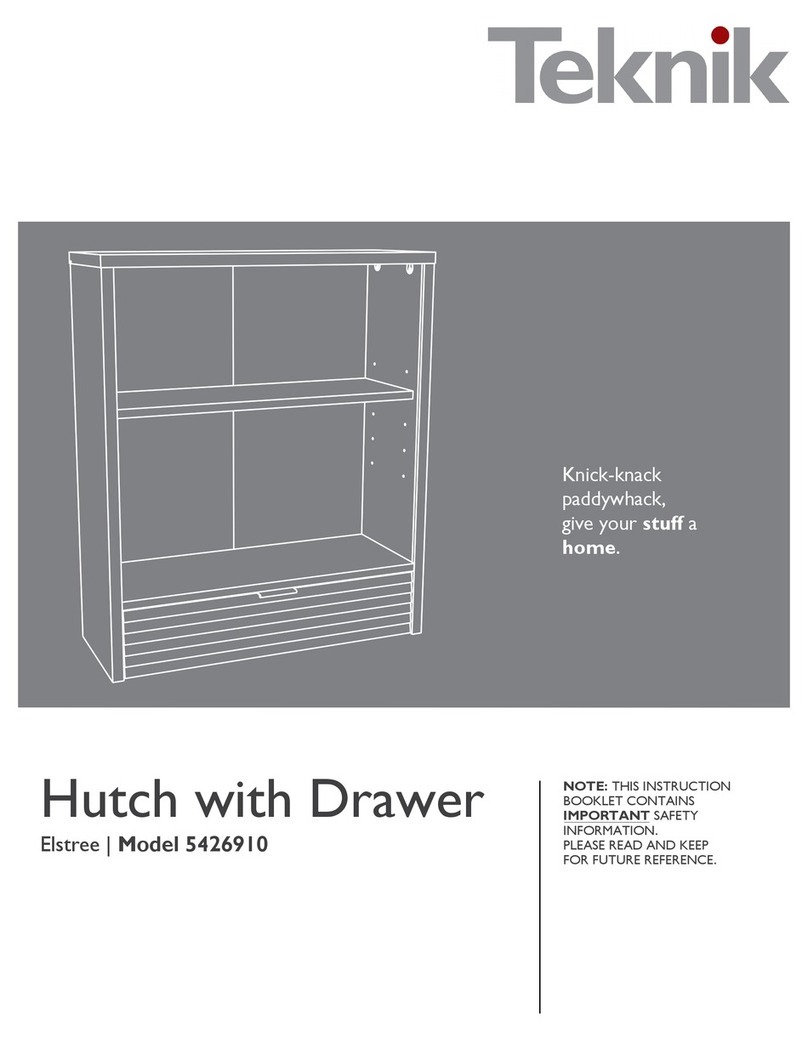
Teknik Barrister Home L-Shaped Desk 5418270 User manual

Teknik

Teknik Barrister Home L-Shaped Desk 5418270 User manual

Teknik 5423912 User manual

Teknik

Teknik 5423912 User manual

Teknik 5431916 User manual

Teknik

Teknik 5431916 User manual

Teknik Hudson 5425825 User manual

Teknik

Teknik Hudson 5425825 User manual

Teknik Elstree Executive Desk 5426918 User manual

Teknik

Teknik Elstree Executive Desk 5426918 User manual

Teknik 5158097 User manual

Teknik

Teknik 5158097 User manual

Teknik Credenza 5421317 User manual

Teknik

Teknik Credenza 5421317 User manual

Teknik City Center 5425658 User manual

Teknik

Teknik City Center 5425658 User manual

Teknik 5424152 User manual

Teknik

Teknik 5424152 User manual

Teknik 5424943 User manual

Teknik

Teknik 5424943 User manual

Teknik Chunky 4 Shelf Bookcase 5422095 User manual

Teknik

Teknik Chunky 4 Shelf Bookcase 5422095 User manual

Teknik 5420649 User manual

Teknik

Teknik 5420649 User manual

Teknik Canal Heights Coffee Table 5419233 User manual

Teknik

Teknik Canal Heights Coffee Table 5419233 User manual

Teknik Hudson Chunky Desk 5425833 User manual

Teknik

Teknik Hudson Chunky Desk 5425833 User manual

Teknik Home Study 5426616 User manual

Teknik

Teknik Home Study 5426616 User manual

Popular Indoor Furnishing manuals by other brands

Crate&Barrel Harbor manual

Crate&Barrel

Crate&Barrel Harbor manual

RH TORANO MARBLE quick start guide

RH

RH TORANO MARBLE quick start guide

Argos 0845 6400800 Assembly instructions

Argos

Argos 0845 6400800 Assembly instructions

Uncle Bills Asia Pacific S002379 instruction manual

Uncle Bills Asia Pacific

Uncle Bills Asia Pacific S002379 instruction manual

ACID Core Products CT114 manual

ACID

ACID Core Products CT114 manual

The Mandir Store MWD-08-117-301-442416 Assembly guide

The Mandir Store

The Mandir Store MWD-08-117-301-442416 Assembly guide

AKRO-MILS ASC1279 Assembly instructions

AKRO-MILS

AKRO-MILS ASC1279 Assembly instructions

overstock CI-60 quick start guide

overstock

overstock CI-60 quick start guide

Noble House Home Furnishings TABLE Assembly instructions

Noble House Home Furnishings

Noble House Home Furnishings TABLE Assembly instructions

Techni Mobili RTA-1458 Assembly instruction

Techni Mobili

Techni Mobili RTA-1458 Assembly instruction

Home Decorators Collection 4083 Stool Use and care guide

Home Decorators Collection

Home Decorators Collection 4083 Stool Use and care guide

Riverside Furniture Joelle Assembly instructions

Riverside Furniture

Riverside Furniture Joelle Assembly instructions

Winsome 81228 R1 quick start guide

Winsome

Winsome 81228 R1 quick start guide

Kathy Ireland 1591MR-22-241 manual

Kathy Ireland

Kathy Ireland 1591MR-22-241 manual

BodyBilt Aircelli Stretch instructions

BodyBilt

BodyBilt Aircelli Stretch instructions

FEZIBO Cubicubi Assembly instructions

FEZIBO

FEZIBO Cubicubi Assembly instructions

Winston HQ3084WTK Assembly instructions

Winston

Winston HQ3084WTK Assembly instructions

Birlea MERCIA FOUR POSTER BED Assembly instruction

Birlea

Birlea MERCIA FOUR POSTER BED Assembly instruction

manuals.online logo
manuals.online logoBrands
  • About & Mission
  • Contact us
  • Privacy Policy
  • Terms and Conditions

Copyright 2025 Manuals.Online. All Rights Reserved.