manuals.online logo
Brands
  1. Home
  2. •
  3. Brands
  4. •
  5. Teknik
  6. •
  7. Indoor Furnishing
  8. •
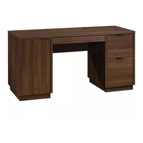
  9. Teknik Barrister Home 5418902 User manual

Teknik Barrister Home 5418902 User manual

NOTE: THIS INSTRUCTION
BOOKLET CONTAINS IMPORTANT
SAFETY INFORMATION.
PLEASE READ AND KEEP FOR
FUTURE REFERENCE.
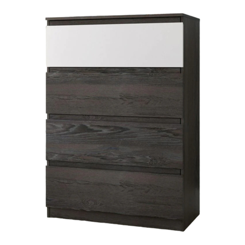
Barrister Home Dresser
Barrister Home Collection | Model 5418902
www.teknikoffice.co.uk
Yes, you still have to
dress yourself.
Teknik
Table of Contents Assembly Tools Required
3
4
5-22
Part Identification
Hardware Identification
Assembly Steps
Hammer
Not actual size
No. 2 Phillips Screwdriver
Tip Shown Actual Size
Skip the power trip.
This time.
Pae 2
Part Identification
åWhile not all parts are labeled, some of the parts will have a label or an inked letter on the ede
to help distinuish similar parts from each other. Use this part identification to help identify similar parts.
A RIGHT END (1)
B LEFT END (1)
C UPRIGHT (1)
D TOP (1)
E BOTTOM (1)
F BACK (1)
G BRACE (2)
H BASE (1)
I RIGHT BASE (1)
J LEFT BASE (1)
K UPPER DRAWER FRONT (2)
L DRAWER FRONT (4)
M FRONT MOLDING (1)
N RIGHT MOLDING (1)
O LEFT MOLDING (1)
P SUPPORT (1)
Q BACK RAIL (1)
R SIDE RAIL (2)
D22 DRAWER RIGHT SIDE (4)
D23 DRAWER LEFT SIDE (4)
D26 SMALL DRAWER RIGHT SIDE (2)
D27 SMALL DRAWER LEFT SIDE (2)
D68 DRAWER BACK (4)
D128 SMALL DRAWER BACK (2)
D977 DRAWER BOTTOM (6)
M64 DRAWER BRACE (6)
Now you know
our ABCs.
Pae 3
A
B
C
D
E
F
G
H
I
J
K
L
M
N
O
P
Q
R
D26
D27
D977
D128
M64
D22
D23
D977
D68
M64
R
G
Hardware Identification
åScrews are shown actual size. You may receive extra hardware with your unit.
Pae 4
5L WARNING LABEL - 1
(Refer to Step 17 for proper
location and application)
WARNING
Serious or fatal crushing injuries can occur
from furniture tip-over. To help prevent
tip-over:
• Place heaviest items in the lowest drawers.
• Unless specifically desined to accommodate, do not
set TVs or other heavy objects on top of this product.
• Never allow children to climb or han on drawers,
doors, or shelves.
• Never open more than one drawer at a time.
• If equipped with a drawer interlock system, do not
defeat or remove it.
Use of tip-over restraints may only reduce, but not
eliminate, the risk of tip-over.
This is a permanent label. Do not attempt to remove!
04/10 332296
35AA UNIVERSAL CABINET RAIL - 12 35AC DRAWER RIGHT - 6 35AD DRAWER LEFT - 6
SAFETY
BRACKET - 1
1G METAL
BRACKET - 11
4G
BLACK 9/16" LARGE HEAD SCREW - 23
1S
SILVER 1-1/8" FLAT HEAD SCREW - 8
10S
BLACK 1-1/4" FLAT HEAD SCREW - 4
7S
BLACK 1-7/8" FLAT HEAD SCREW - 11
2S
BLACK 7/8" MACHINE SCREW - 24
37S
3S GOLD 5/16" FLAT HEAD SCREW - 48
METAL
PIN - 8
1R
MOLDING
CONNECTOR - 2
19F
10A SLIDE CAM - 12
NAIL - 48
1N
HIDDEN
CAM - 16
1F CAM DOWEL - 16
2F
30S BLACK 1-9/16" FLAT HEAD SCREW - 30
KNOB - 8
71K
PULL - 8
70K
Step 1
å Assemble your unit on a carpeted floor or on the empty
carton to avoid scratchin your unit or the floor.
å Push sixteen HIDDEN CAMS (1F) into the ENDS (A and B),
UPRIGHT (C), BOTTOM (E), and DRAWER BRACES (M64).
Then, insert the metal end of a CAM DOWEL (2F) into each
HIDDEN CAM.
Pae 5
Arrow
1F
2F
(16 used)
Arrow
1F
2F
Do not tihten the HIDDEN CAMS in this step.
Insert the metal end of the CAM
DOWEL into the HIDDEN CAM.
Arrow
A
B
C
M64
E
M64 M64
M64 M64
M64
Step 2
å Fasten six UNIVERSAL CABINET RAILS* (35AA) to the
ENDS (A and B). Use twelve GOLD 5/16" FLAT HEAD
SCREWS (3S) throuh holes #1 and #3.
å *patent pendin lide system
Pae 6
GOLD 5/16" FLAT HEAD SCREW
(12 used in this step)
3S
3
2
1
1
2
3
A
1
2
31
2
3
3
2
13
2
1
Glide end
Glide end
Finished ede
Surface with
HIDDEN CAMS
B
Surface with
HIDDEN CAMS
Finished ede
Remember:
Rihty tihty.
Lefty loosey.
å Fasten six UNIVERSAL CABINET RAILS* (35AA) to
the UPRIGHT (C). Use twelve GOLD 5/16" FLAT HEAD
SCREWS (3S) throuh holes #1 and #3.
å *patent pendin lide system
Step 3
Pae 7
Finished ede
Glide end
Glide end
C
Surface with
HIDDEN CAMS
Ede with
CAM DOWELS
GOLD 5/16" FLAT HEAD SCREW
(12 used in this step)
3S
1
2
3
3
3
1
2
31
2
3
1
2
3
Step 4
å Fasten the TOP (D) to the RAILS (Q and R). Use eiht
BLACK 1-7/8" FLAT HEAD SCREWS (2S).
Pae 8
Q
R
R
D
Curved ede
Surface with fewer holes
BLACK 1-7/8" FLAT HEAD SCREW
(8 used in this step)
2S
Step 5
Pae 9
å Tap two MOLDING CONNECTORS (19F) into the notches
in the MOLDINGS (M, N, and O).
Flat end
19F
N
O
M
19F
Unfinished surface
Flat end
Use your hammer to tap the MOLDING CONNECTORS (19F) into the notches in the MOLDINGS.
Unfinished surface
Step 6
Pae 10
å Fasten the TOP (D) to the MOLDINGS (M, N, and O). Use
eiht SILVER 1-1/8" FLAT HEAD SCREWS (10S).
å NOTE: Do not overtihten the SCREWS into the TOP.
O
N
D
M
Finished surface
Finished surface
Surface with more holes
Finished surface
SILVER 1-1/8" FLAT HEAD SCREW
(8 used in this step)
10S
Do not overtihten
the SCREWS (10S).
Q
å Fasten the UPRIGHT (C) to the BOTTOM (E). Use two
BLACK 1-7/8" FLAT HEAD SCREWS (2S).
Step 7
Pae 11
BLACK 1-7/8" FLAT HEAD SCREW
(2 used in this step)
2S
E
C
Surface with
HIDDEN CAMS
Surface
with
HIDDEN
CAMS
Finished ede
These holes
must be here.
Do not stand the unit upriht without the
BACK fastened. The unit may collapse.
Caution
Step 8
å Insert eiht METAL PINS (1R) into the holes in the ENDS (A
and B) and UPRIGHT (C).
å Place the BRACES (G) onto the METAL PINS in the UPRIGHT (C).
å Fasten the ENDS (A and B) to the BOTTOM (E). Tihten four
HIDDEN CAMS.
å NOTE: Be sure the METAL PINS in the ENDS (A and B) insert into
the holes in the ends of the BRACES (G).
Pae 12
Start Tighten
Arrow
Minimum
190 derees
Caution
Risk of damae or
injury. HIDDEN CAMS
must be completely
tihtened. HIDDEN
CAMS that are not
completely tihtened
may loosen, and parts
may separate. To
completely tihten:
Arrow
Maximum
210 derees
A
Surface
with
HIDDEN
CAMS
Finished ede
B
Surface
without
HIDDEN
CAMS
Finished ede
C
E
Finished ede
Finished ede
1R
1R
1R G
G
å Fasten the TOP (D) to the UPRIGHT (C). Tihten two
HIDDEN CAMS.
å Fasten the MOLDINGS (N and O) to the ENDS (A and B).
Tihten four HIDDEN CAMS.
Step 9
Pae 13
Arrow
Minimum
190 derees
Maximum
210 derees
A
B
D
C
O
N
M
Step 10
å Fasten the BASES (I and J) to the ENDS (A and B). Use
four BLACK 1-1/4" FLAT HEAD SCREWS (7S).
Pae 14
B
A
I
J
BLACK 1-1/4" FLAT HEAD SCREW
(4 used in this step)
7S
Flat ede
Flat ede
å Fasten eiht METAL BRACKETS (4G) to the ENDS (A
and B) and BOTTOM (E). Use eiht BLACK 9/16" LARGE
HEAD SCREWS (1S).
å NOTE: Be sure the edes of the METAL BRACKETS are even
with the edes of the ENDS and BOTTOM.
å Fasten the BASE (H) to the ENDS (A and B) and BOTTOM (E).
Use eiht BLACK 9/16" LARGE HEAD SCREWS (1S) throuh
the METAL BRACKETS and into the BASE.
Step 11
Pae 15
BLACK 9/16" LARGE HEAD SCREW
(16 used in this step)
1S
Flat ede
B
H
E
4G
4G
4G
A
Step 12
Pae 16
BLACK 9/16" LARGE HEAD SCREW
(6 used for the SUPPORT)
1S
å Carefully turn your unit over onto its front edes. Unfold
the BACK (F) and lay it over your unit.
å Make equal marins alon all four edes of the BACK (F).
Push on opposite corners of your unit if needed to make
it "square".
å Fasten the BACK (F) to your unit usin the NAILS (1N).
å NOTE: Be sure to tap NAILS into the holes that line up over
the UPRIGHT (C).
å Fasten three METAL BRACKETS (4G) to the SUPPORT (P).
Use three BLACK 9/16" LARGE HEAD SCREWS (1S).
å NOTE: Be sure the edes of the METAL BRACKETS are
even with the ede of the SUPPORT.
å Fasten the SUPPORT (P) to the BOTTOM (E). Use three
BLACK 9/16" LARGE HEAD SCREWS (1S) throuh the
METAL BRACKETS and into the BOTTOM.
Do not stand the unit upriht without the
BACK fastened. The unit may collapse.
Caution
These holes must line up
over the UPRIGHT (C).
NAIL
(48 used for the BACK)
1N
F
P
4G
4G
P
E
Printed
information
must be
facin up.
Step 13
Pae 17
å Insert the DRAWER SIDES (D22 and D23) at an angle
into the slot at each end of the DRAWER FRONT (L). å Slide the DRAWER BOTTOM (D977) into the
grooves in the DRAWER SIDES (D22 and D23) and
DRAWER FRONT (L).
å Fasten the DRAWER BRACE (M64) to the DRAWER
FRONT (L). Tighten one HIDDEN CAM. å Fasten the DRAWER BACK (D68) to the DRAWER
SIDES (D22 and D23) and DRAWER BRACE (M64). Use
five BLACK 1-9/16" FLAT HEAD SCREWS (30S). Repeat
this step for the other DRAWERS. Use parts K, D26, D27,
D128, D977 and M64 for the small drawers.
12
34
Be sure the DRAWER
BOTTOM inserts into the
DRAWER FRONT roove.
With the palm of your hand,
tap the DRAWER BOTTOM
down into the roove.
Groove
Arrow
Maximum
210 derees
Minimum
190 derees
L
L
L
D23
D22
D23
D977
D22
D22
D23
D68
Unfinished
surface
Be sure the
DRAWER
BOTTOM
inserts into
the DRAWER
BACK roove.
30S
Start each screw a few turns before
completely tihtenin any of them.
BLACK 1-9/16" FLAT HEAD SCREW
(30 used in this step)
The tabs should insert freely
into the slots. Gently tilt the
DRAWER SIDES side to side
until the tabs slip into the slots.
M64
M64
Surface with
HIDDEN CAM
Step 14
Pae 18
å Insert a SLIDE CAM (10A) into the DRAWER SIDES (D22 and D23).
å Fasten a DRAWER RIGHT (35AC) to the DRAWER RIGHT SIDE (D22)
and a DRAWER LEFT (35AD) to the DRAWER LEFT SIDE (D23). Use
four GOLD 5/16" FLAT HEAD SCREWS (3S) throuh holes #1 and #2.
å NOTE: The screw head in the CAM must be visible throuh the slotted
hole in the SLIDE.
å NOTE: The parts are marked "DRAWER RIGHT" and "DRAWER LEFT"
for easy identification.
å NOTE: The lides are not intended to rotate.
å Repeat this step for the other drawers.
Screw head - turn CAM to line up holes in
the SLIDES with holes in DRAWER SIDES
10A
10A
1
2
1
2
Glide end
Glide end
GOLD 5/16" FLAT HEAD SCREW
(24 used in this step)
3S
(4 screws per drawer)
D23
D22
Step 15
Pae 19
å Fasten four KNOBS (71K) to the UPPER DRAWER FRONT (K).
Use four BLACK 7/8" MACHINE SCREWS (37S).
å Fasten two PULLS (70K) to the DRAWER FRONT (L). Use four
BLACK 7/8" MACHINE SCREWS (37S).
å Repeat this step for the remainin drawers.
BLACK 7/8" MACHINE SCREW
(24 used in this step)
37S
70K
71K
L
K
Step 16
Pae 20
å Carefully stand your unit upriht.
å We recommend usin the SAFETY BRACKET (1G)
for added stability. Use a BLACK 9/16" LARGE HEAD
SCREW (1S) into the underneath surface of the TOP (D)
and a BLACK 1-7/8" FLAT HEAD SCREW (2S) into a stud
in your wall.
1G
BLACK 1-7/8" FLAT HEAD SCREW
(1 used into a stud in your wall)
2S
BLACK 9/16" LARGE HEAD SCREW
(1 used into your unit)
1S
D

Other Teknik Indoor Furnishing manuals

Teknik 5401562 User manual

Teknik

Teknik 5401562 User manual

Teknik 5158097 User manual

Teknik

Teknik 5158097 User manual

Teknik Metro 5426461 User manual

Teknik

Teknik Metro 5426461 User manual

Teknik Denver Swivel Recliner User manual

Teknik

Teknik Denver Swivel Recliner User manual

Teknik 5420275 User manual

Teknik

Teknik 5420275 User manual

Teknik Office Affiliate 5427414 User manual

Teknik

Teknik Office Affiliate 5427414 User manual

Teknik Barrister Home Credenza 5421458 User manual

Teknik

Teknik Barrister Home Credenza 5421458 User manual

Teknik Market 5425767 User manual

Teknik

Teknik Market 5425767 User manual

Teknik 5427872 User manual

Teknik

Teknik 5427872 User manual

Teknik 5424944 User manual

Teknik

Teknik 5424944 User manual

Teknik 5426484 User manual

Teknik

Teknik 5426484 User manual

Teknik 5427129 User manual

Teknik

Teknik 5427129 User manual

Teknik Clifton Place 5421116 User manual

Teknik

Teknik Clifton Place 5421116 User manual

Teknik White Home Study L-Shaped Desk User manual

Teknik

Teknik White Home Study L-Shaped Desk User manual

Teknik Chunky 4 Shelf Bookcase 5422095 User manual

Teknik

Teknik Chunky 4 Shelf Bookcase 5422095 User manual

Teknik Barrister Home 5418891 User manual

Teknik

Teknik Barrister Home 5418891 User manual

Teknik Hudson Elm finish 5427422 User manual

Teknik

Teknik Hudson Elm finish 5427422 User manual

Teknik 5424943 User manual

Teknik

Teknik 5424943 User manual

Teknik Canyon Lane 5425306 User manual

Teknik

Teknik Canyon Lane 5425306 User manual

Teknik Credenza 5421317 User manual

Teknik

Teknik Credenza 5421317 User manual

Teknik 5427030 User manual

Teknik

Teknik 5427030 User manual

Teknik City Center 5425658 User manual

Teknik

Teknik City Center 5425658 User manual

Teknik Elstree L-Shaped Desk 5426914 User manual

Teknik

Teknik Elstree L-Shaped Desk 5426914 User manual

Teknik Boulevard Cafe 5420667 User manual

Teknik

Teknik Boulevard Cafe 5420667 User manual

Popular Indoor Furnishing manuals by other brands

Otto LKZ 41164 Assembly instructions

Otto

Otto LKZ 41164 Assembly instructions

BROSA Lucille Round Table Assembly guide

BROSA

BROSA Lucille Round Table Assembly guide

LINSY HOME LS200E4-A Assembly instructions

LINSY HOME

LINSY HOME LS200E4-A Assembly instructions

Polini kids Simple manual

Polini kids

Polini kids Simple manual

We BTNAP Assembly instructions

We

We BTNAP Assembly instructions

Stryker 4821 Operation & maintenance manual

Stryker

Stryker 4821 Operation & maintenance manual

Walker Edison AF48CYET Assembly instructions

Walker Edison

Walker Edison AF48CYET Assembly instructions

IMG Group Scandi Assembly instructions

IMG Group

IMG Group Scandi Assembly instructions

FURNITUREBOX OXFORD BEDSIDE TABLE Assembly guide

FURNITUREBOX

FURNITUREBOX OXFORD BEDSIDE TABLE Assembly guide

Homelegance 194S4615-F1 Assembly instruction

Homelegance

Homelegance 194S4615-F1 Assembly instruction

Balkene Home Vega 62772 instructions

Balkene Home

Balkene Home Vega 62772 instructions

Triarch 31371 Assembly instructions

Triarch

Triarch 31371 Assembly instructions

FUFU & GAGA KF180131-01 manual

FUFU & GAGA

FUFU & GAGA KF180131-01 manual

LOXONE 100177 quick start guide

LOXONE

LOXONE 100177 quick start guide

THB Wardrobe Absolut Plus 7 Doors Assembly instructions

THB

THB Wardrobe Absolut Plus 7 Doors Assembly instructions

Tradecraft Specialties BULLDOZ-9 instruction manual

Tradecraft Specialties

Tradecraft Specialties BULLDOZ-9 instruction manual

Rocker COSMOS RGB 2112001 Assembly instructions

Rocker

Rocker COSMOS RGB 2112001 Assembly instructions

Forte OIRV711B Assembling Instruction

Forte

Forte OIRV711B Assembling Instruction

manuals.online logo
manuals.online logoBrands
  • About & Mission
  • Contact us
  • Privacy Policy
  • Terms and Conditions

Copyright 2025 Manuals.Online. All Rights Reserved.