manuals.online logo
Brands
  1. Home
  2. •
  3. Brands
  4. •
  5. Wren Kitchens
  6. •
  7. Indoor Furnishing
  8. •
  9. Wren Kitchens 2070 User manual

Wren Kitchens 2070 User manual

TOWER UNIT
2070 & 2250 Diagonal Corner Office Assembly Guide
For Internal Use: FI.WR.INS.114_WKIN00175_Diagonal_Corner_Oce_Rev2
2070 - 2250 x 1302
1 Door 50/50 Door
70/30 Door
Page 1
TOWER UNIT
2070 & 2250 Diagonal Corner Office Assembly Guide
Panel eA x1
End Panel
Left Hand
Panel eB x1
End Panel
Right Hand
Panel bK
x1 Back Panel
Left Hand
Panel bL
x1 Back Panel
Right Hand
Panel sH
x1 Top Panel
Panel sE
x1 Fixed Shelf
Frontals
1Dr or 50/50 or 70/30
(Packed Separately)
Plinth
x2
L Bracket (LGE)
x4
Fixing Plate (U)
Hinge Mounting Plate
Inc Screws
Hinge
Inc Screws
NOT to be
used with
CAM DOWEL
& CAM LOCK
REQUIRED TOOLS
70/30 OPTION
1DOOR
OPTION
50/50 OPTION
Screw Cover Cap
x 4 (Per Colour)
Panel eC x1
End Panel
Left Hand
Panel eD x1
End Panel
Right Hand
Panel sF
x1 Fixed Shelf
Panel sG
x2 Fixed Shelf
Panel bM
x1 Back Panel
Left Hand
Panel bN
x1 Back Panel
Right Hand
Door Buer
x1
Wooden Dowel (F)
x 70
Cam Lock (H)
x 30
Cam Dowel (W)
x 30 45mm Screw (P)
x 42
15mm Screw (L) 30mm Screw (K)
x 16
BEFORE YOU START
INSTALLATION
SHOULD BE PERFORMED
BY A COMPETENT PERSON
ONLY.
THIS PRODUCT COULD
BE DANGEROUS IF
INCORRECTLY INSTALLED
Page 2
For Internal Use: FI.WR.INS.114_WKIN00175_Diagonal_Corner_Oce_Rev2
Step 2.
Seat 2 wooden dowels (F) into
holes in panel (sE) as shown.
Step 1.
Seat 4 cam dowels (W) into holes
in end panel (eC) as shown.
Step 4.
Insert 2 cam locks (H) into holes in
panel (sE) as shown.
Do NOT tighten until step 16.
Step 3.
Attach panel (sE) to end panel (eC),
using cam dowels (W) (in blue) and
wooden dowels (F) (in orange) in
positions as shown.
F
F
F
F
sE
eC FFF
Step 5.
Seat 8 wooden dowels (F) into holes
in panel (sE) and 3 wooden dowels (F)
into holes in end panel (eC) as shown.
F
F
sE
FFFF
eC
WWW
W
WDo not use power tools with
cam dowel (W) or cam lock (H)
sE
eC
H
H
Inside view
Back right view
Step 6.
Attach back panel (bM) to end panel (eC)
and panel (sE), using cam dowels (W) (in
blue) and wooden dowels (F) (in orange)
in positions as shown.
bM
Back right view
eC W
W
Once back panel (bM) is in position, ensure it is
ush & square with bottom of end panel (eC).
sE
eC
bM
Front view
Front view eC
sE
Page 3
TOWER UNIT
2070 & 2250 Diagonal Corner Office Assembly Guide
Step 7.
Insert 2 cam locks (H) into holes in
back panel (bM) as shown.
Do NOT tighten until step 16.
Step 11.
Secure back panel (bN) to back
panel (bM), using 5 x 45mm
screws (P) as shown.
Step 9.
Attach back panel (bN) to panel (sE),
using wooden dowels (F) (in orange)
in positions as shown.
Step 10.
Secure back panel (bN) to panel (sE),
using 3 x 45mm screws (P) as shown.
Do not use power tools with
cam dowel (W) or cam lock (H)
P
P
P
bM
bN
sE
Back view
Step 8.
Secure back panels (bM) to panel (sE),
using 3 x 45mm screws (P) as shown.
P
P
P
bM
Back right view
sE
bM
sE
bN
Back view
PPPPP
bM
sE
Back view
bN
bM
eC
Back right view
H
H
Page 4
For Internal Use: FI.WR.INS.114_WKIN00175_Diagonal_Corner_Oce_Rev2
Step 12.
Seat 2 wooden dowels (F) into holes in panel
(sE) and 3 wooden dowels (F) into holes in
back panel (bN) as shown.
Step 13.
Seat 4 cam dowels (W) into holes in end
panel (eD) as shown.
Step 14.
Attach end panel (eD) to back panel (bN) and panel (sE),
using cam dowels (W) (in blue) and wooden dowels (F)
(in orange) in positions as shown.
W
W
W
W
eD
Step 15.
Insert 2 cam locks (H) per panel into holes in
back panel (bN) and in panel (sE)
Inside view
Step 16.
Hand tighten all cam locks (H),
this will expand cam dowels
(W) and tighten the unit
together.
sE
eC
H
H
Do not use power tools with
cam dowel (W) or cam lock (H)
F
F
FFF
bN
bM
eC
sE
Front view
Inside view
Back view
W
bN
sE
bM
eD
Back view
Step 17.
Secure unit to wall, using L brackets LGE. Use 2 x
15mm screws (L) to secure each of the L brackets
LGE to the end panel at either side. Then screw
through into the wall as shown.
L
L
Screws for xing to walls are not provided as these vary
depending on your wall material and construction. Ensure
appropriate xings for wall constructions are used.
Front view
sE
bN
H
H
eD
sE
bN
H
H
Page 5
TOWER UNIT
2070 & 2250 Diagonal Corner Office Assembly Guide
Step 18.
Seat 11 cam dowels (W) into holes
in end panel (eA) as shown.
Step 19.
Seat 2 wooden dowels (F) per panel into
holes in panel (sF) and (sH) as shown.
Seat 1 wooden dowel (F) per panel into hole
in panels (sG) as shown.
Step 20.
Attach panels (sF), (sG), (sH), to end
panel (eA), using cam dowels (W) (in
blue) and wooden dowels (F) (in orange)
in positions as shown.
sF
eA
sG
sG
sH
Step 21.
Insert 2 cam locks (H) per panel into holes in panels (sF),
(sG) and (sH) as shown. Do NOT tighten until step 33.
eA
W
W
W
WW
W
W
W
W
W
W
W
Do not use power tools with
cam dowel (W) or cam lock (H)
Front view
sF
eA
H
H
Front view
sH
eA H
H
Inside view
sG
eA
H
sG
H
H
Inside view
H
F
F
F
F
F
F
sF
sG
sG
sH
Page 6
For Internal Use: FI.WR.INS.114_WKIN00175_Diagonal_Corner_Oce_Rev2
Step 22.
Seat 8 wooden dowels (F) per panel into holes in
panels (sF), (sG) and (sH) and 4 wooden dowels
(F) into holes in end panel (eA) as shown.
Do not use power tools with
cam dowel (W) or cam lock (H)
sF
sG
sH
F
F
F
F
F
F
F
F
F
F
F
F
F
F
F
F
sG
eA
F
F
F
F
F
F
F
F
F
F
F
F
F
F
F
F
Back right view
F
F
F
F
eA
sG sG
Back right view
Step 23.
Attach back panel (bK) to end panel (eA) and panels (sF),
(sG),(sH), using cam dowels (W) (in blue) and wooden
dowels (F) (in orange) in positions as shown.
Once back panel (bK) is in position, ensure it is ush
& square with bottom of end panel (eA).
Back right view
sF
bK
eA
W
W
W
sF
eA bK
sG sG sH
Back right view
Step 24.
Insert 3 cam locks (H) into holes in
back panel (bK) as shown.
Do NOT tighten until step 33.
bK
sF
Back right view
H
H
H
Page 7
TOWER UNIT
2070 & 2250 Diagonal Corner Office Assembly Guide
Step 26.
Attach back panel (bL) to panels (sF), (sG),
(sH), using wooden dowels (F) (in orange) in
positions as shown.
Step 25.
Secure back panel (bK) to panels (sF),
(sG) and (sH), using 12 x 45mm screws
(P) as shown.
P
PPP
P
PPP
P
PPP
bK sG
sG
sF
sH
Back view
Step 28.
Secure back panel (bL) to back panel (bK),
using 7 x 45mm screws (P) as shown.
Step 27.
Secure back panel (bL) to panels (sF), (sG) and
(sH), using 12 x 45mm screws (P) as shown.
Back view
P
P
P
P
P
P
P
sH
bK
bL
Back view
P
P
P
P
P
P
P
P
P
P
P
P
sH
bK
bL
sH
bK
bL
Back view
Page 8
For Internal Use: FI.WR.INS.114_WKIN00175_Diagonal_Corner_Oce_Rev2
Step 29.
Seat 2 wooden dowels (F) per panel into
holes in panel (sF) and (sH) as shown.
Seat 1 wooden dowel (F) per panel into
hole in panels (sG) as shown.
Seat 4 wooden dowels (F) into holes in back
panel (bL) as shown.
Step 30.
Seat 11 cam dowels (W) into holes
in end panel (eB) as shown.
Step 31.
Attach end panel (eB) to back panel (bL) and panels
(sF), (sG), (sH), using cam dowels (W) (in blue) and
wooden dowels (F) (in orange) in positions as shown.
Step 32.
Insert 3 cam locks (H) into holes in back panel (bL) and 2
cam locks (H) per panel in panels (sF), (sG), (sH). Step 33.
Hand tighten all cam locks (H). This will expand cam
dowels (W) and tighten the unit together.
H
H
sF
bL
sG
eB
sG
sH
Do not use power tools with
cam dowel (W) or cam lock (H)
F
F
F
FF
F
F
FF
F
bL
bK
eA
sF
sG sG
sH
Front view
bL
sH
bK
eB
W
Back view
Inside view
Back right view
eB
W
W
W
W
W
W
W
W
W
W
W
H
H
H
H
H
HH
bK
eB H
H
H
H
eB
bL
sF
H
Back right view
Page 9
TOWER UNIT
2070 & 2250 Diagonal Corner Office Assembly Guide
Step 34.
Make sure bottom unit is attached to walls.
Place top unit on bottom unit, ensure end panel (eA)
is ush with end panel (eC) and end panel (eB) is
ush with end panel (eD).
Step 35.
Secure top unit to bottom unit,
using 10 x 30mm screws (K) as
shown. Screw through panel (sE).
View From Underside
sE
sF
sH
K
K
K
K
K
K K
K
K
K
Step 36.
Once top and bottom units are connected, secure top unit to
wall, using L brackets LGE. Use 2 x 15mm screws (L) to secure
each of the L brackets LGE to the end panel at either side.
Then screw through into the wall as shown.
Screws for xing to walls are not provided as these vary
depending on your wall material and construction. Ensure
appropriate xings for wall constructions are used.
L
L
Front view
eA eB
eC eD
Front view
sE
sF
sE
Inside view
bM
eC
sF
K
K
KK
DO NOT screw through
panel (sF).
Page 10
For Internal Use: FI.WR.INS.114_WKIN00175_Diagonal_Corner_Oce_Rev2
2070mm unit
50/50 Door and 1 Door
HINGE POSITION
276mm
244mm
Front
Top
eA & eB
INSIDE FACE
eC & eD
2070mm unit
70/30 Door
HINGE POSITION
276mm
244mm
Front
Top
eA & eB
INSIDE FACE
eC & eD
1976mm
996mm
1486mm
776mm
1944mm
964mm
1454mm
744mm
1976mm
1236mm
1016mm
1944mm
1204mm
984mm
Step 37.
Attach hinge plates to the inside face of end panels
on the left side (eA) and (eC) and end panels on
the right side (eB) and (eD) to suit as shown.
Hinge side to be mounted in accordance to
customer specic kitchen plan. eA eB
eC eD
1 Door
50/50 Door
70/30 Door
Bottom Bottom
LH & RH
LH & RH
Hinge plate
Page 11
TOWER UNIT
2070 & 2250 Diagonal Corner Office Assembly Guide
2250mm unit
50/50 Door
HINGE POSITION
2156mm
276mm
2124mm
244mm
Front
Top
eA & eB
INSIDE FACE
eC & eD
1176mm
1666mm
956mm
1144mm
1634mm
924mm
2250mm unit
70/30 Door
HINGE POSITION
2156mm
276mm
2124mm
244mm
Front
Top
eA & eB
INSIDE FACE
eC & eD
996mm
1576mm
776mm
964mm
1544mm
744mm
Step 37.
Attach hinge plates to the inside face of end panels
on the left side (eA) and (eC) and onto end panels
on the right side (eB) and (eD) to suit as shown.
Hinge side to be mounted in accordance to
customer specic kitchen plan. eA eB
eC eD
70/30 Door
50/50 Door
Bottom Bottom
LH & RH
LH & RH
Hinge plate
Page 12
For Internal Use: FI.WR.INS.114_WKIN00175_Diagonal_Corner_Oce_Rev2
2250mm unit
1 Door
HINGE POSITION
2156mm
1351.5mm
1080.5mm
1319.5mm
1048.5mm
276mm
2124mm
244mm
Front
Top
eA & eB
INSIDE FACE
eC & eD
Step 37.
Attach hinge plates to the inside face of end panels
on the left side (eA) and (eC) and onto end panels
on the right side (eB) and (eD) to suit as shown.
Hinge side to be mounted in accordance to
customer specic kitchen plan. eA eB
eC eD
1 Door
Bottom
LH & RH
Hinge plate
Page 13
TOWER UNIT
2070 & 2250 Diagonal Corner Office Assembly Guide
U
U
U
UU
U
1DOOR OPTION50/50 & 70/30
OPTIONS
Step 2.
Align doors & frontal plinth to join together
using xing plates (U) to the back of both
frontals. Ensure a 4mm gap is maintained
between each frontal once xed together.
Screw in place using 4 x 15mm screws (L)
per xing plate (U).
Fixing plate
Step 3.
Secure hinges by tightening 2 x screws with
hinge dowels attached. These are already
positioned within the hinges.
Door Frontal Fixing (Where Applicable)
Innity +
Doors Supplied in accordance to
customer specic kitchen plan
Hinge dowels
Step 4.
Attach the door to unit, clip hinge onto
hinge plate and click to secure.
Step 1.
Insert hinge into hinge holes provided, in
accordance with customers plan.
Hinge cover caps
Step 5.
Adjust hinge to suit. As shown below.
Hinge plates
View from Inside of unit
To adjust hinge using
a screw driver, tighten
or loosen as required at
points 1 & 2.
Point 1- In - Out
Point 2- Left - Right
1
2
FRONTAL
HINGE
ADJUSTMENT
To release door, pull
catch as shown, to
release hinge from
the hinge plate.
Step 6.
Fit cover caps to hinge.
Adjust softclose to suit.
The top and bottom
hinges MUST be
adjusted to the SAME
STRENGTH.
To move the
hinge up/down,
loosen screws
A + B,
manoeuvre
the door, then
re-tighten the
screws
A
B
Page 14
For Internal Use: FI.WR.INS.114_WKIN00175_Diagonal_Corner_Oce_Rev2

Other manuals for 2070

2

This manual suits for next models

1

Other Wren Kitchens Indoor Furnishing manuals
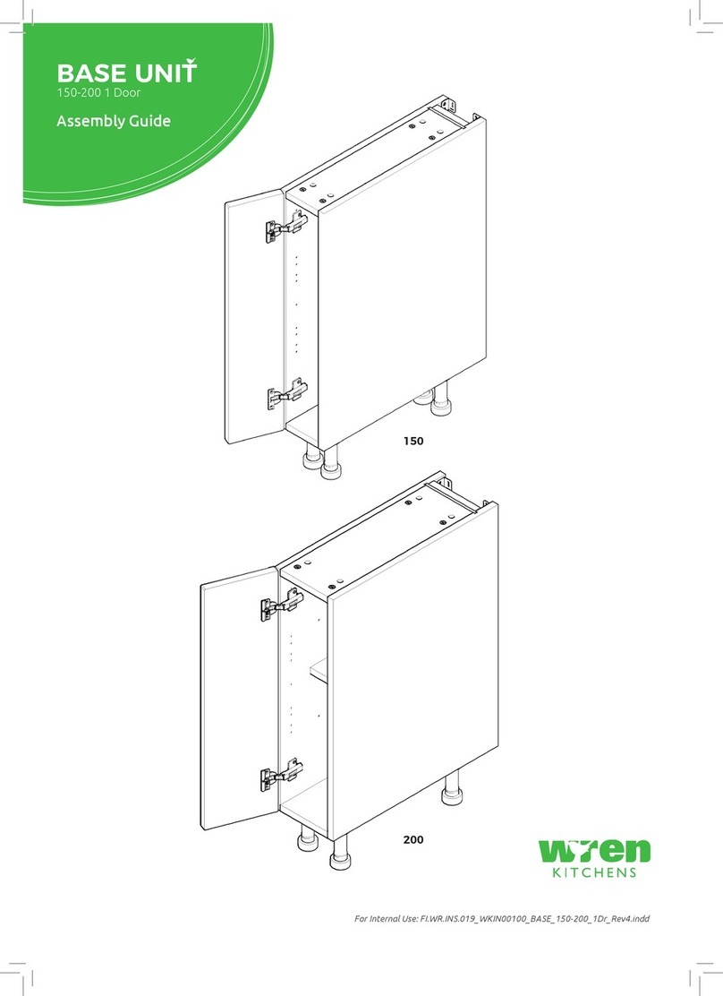
Wren Kitchens Vogne 150 User manual

Wren Kitchens

Wren Kitchens Vogne 150 User manual

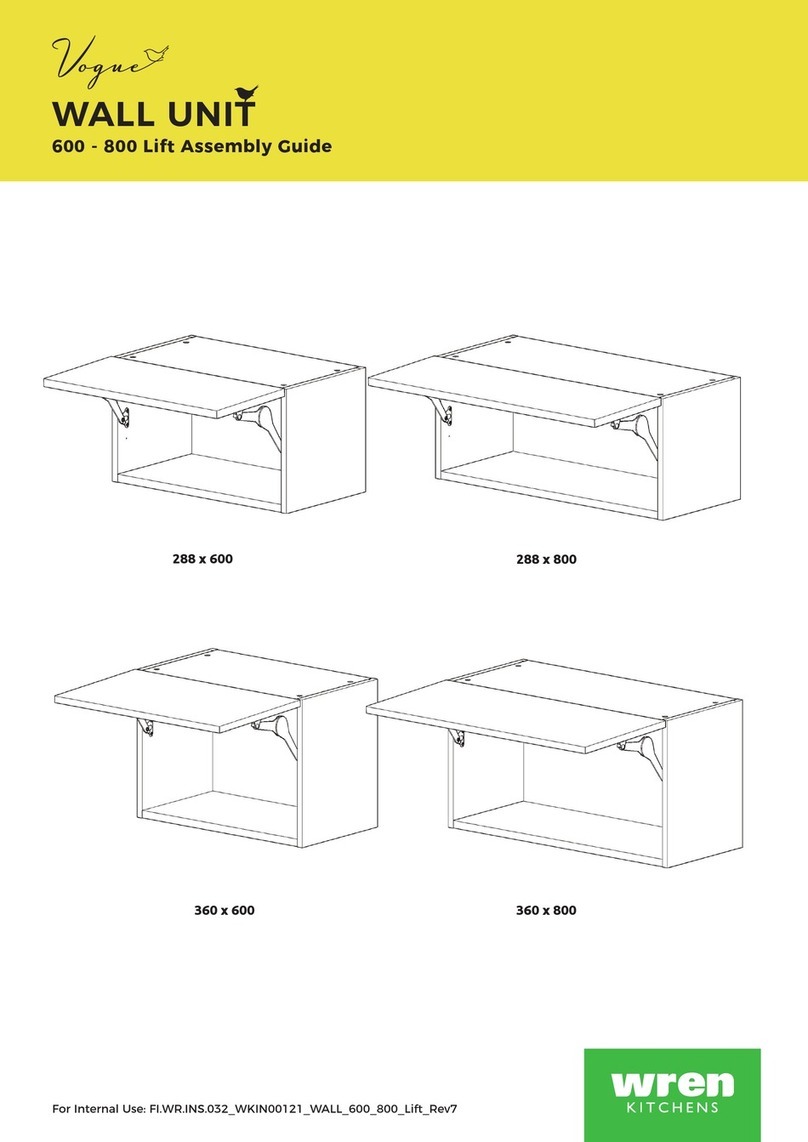
Wren Kitchens Vogue TOWER UNIT 600 2 Door Fridge / Freezer User manual

Wren Kitchens

Wren Kitchens Vogue TOWER UNIT 600 2 Door Fridge / Freezer User manual

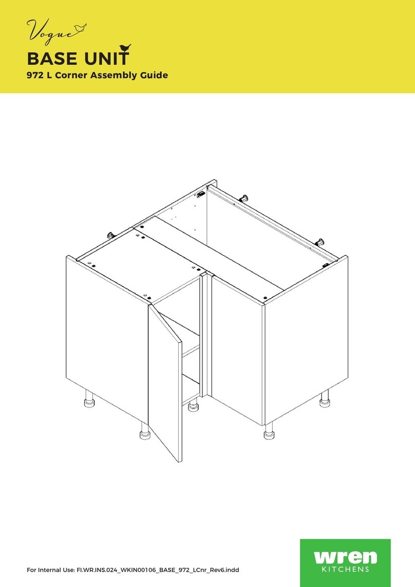
Wren Kitchens Vogue BASE UNIT 1000 2 Door User manual

Wren Kitchens

Wren Kitchens Vogue BASE UNIT 1000 2 Door User manual

Wren Kitchens Diag Corner Larder User manual

Wren Kitchens

Wren Kitchens Diag Corner Larder User manual

Wren Kitchens BASE UNIT 600 User manual

Wren Kitchens

Wren Kitchens BASE UNIT 600 User manual

Wren Kitchens 1000 Base Shallow User manual

Wren Kitchens

Wren Kitchens 1000 Base Shallow User manual

Wren Kitchens Industrial Island User manual

Wren Kitchens

Wren Kitchens Industrial Island User manual

Wren Kitchens 2070 User manual

Wren Kitchens

Wren Kitchens 2070 User manual

Wren Kitchens 150 Pull Out User manual
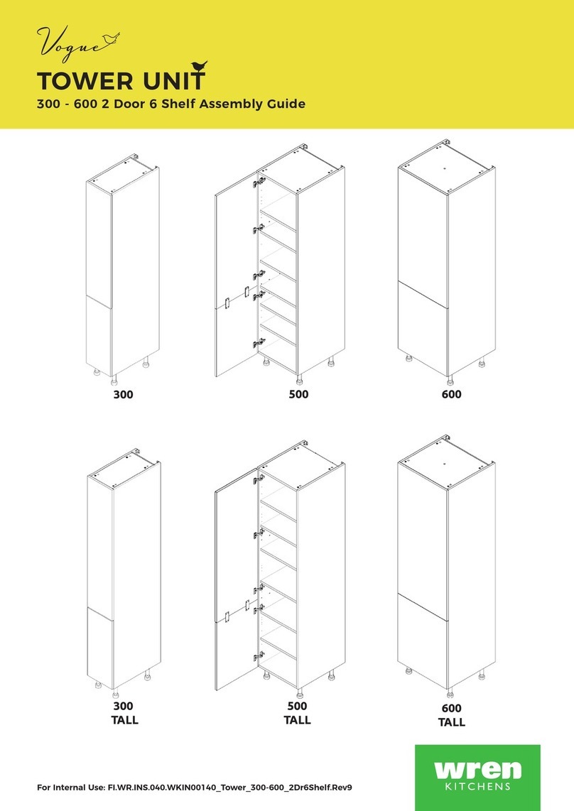
Wren Kitchens

Wren Kitchens 150 Pull Out User manual

Wren Kitchens BASE 3 MILANO Assembly instructions

Wren Kitchens

Wren Kitchens BASE 3 MILANO Assembly instructions

Wren Kitchens Vogue BASE UNIT 1000 2 Door User manual

Wren Kitchens

Wren Kitchens Vogue BASE UNIT 1000 2 Door User manual

Wren Kitchens Vogue WALL UNIT 672 Tall L Corner User manual

Wren Kitchens

Wren Kitchens Vogue WALL UNIT 672 Tall L Corner User manual

Wren Kitchens L Corner Base Unit Assembly instructions

Wren Kitchens

Wren Kitchens L Corner Base Unit Assembly instructions

Wren Kitchens Vogue 600 User manual

Wren Kitchens

Wren Kitchens Vogue 600 User manual

Wren Kitchens FI.PK.FIT.004 User manual

Wren Kitchens

Wren Kitchens FI.PK.FIT.004 User manual

Wren Kitchens Vogue WALL UNIT 600 Lift User manual

Wren Kitchens

Wren Kitchens Vogue WALL UNIT 600 Lift User manual

Wren Kitchens Vogue BASE UNIT 600 2 Drawer User manual

Wren Kitchens

Wren Kitchens Vogue BASE UNIT 600 2 Drawer User manual

Wren Kitchens Vogue WALL UNIT 150 Tall 1 Door User manual

Wren Kitchens

Wren Kitchens Vogue WALL UNIT 150 Tall 1 Door User manual

Wren Kitchens Vogue BASE UNIT 150 1 Door User manual

Wren Kitchens

Wren Kitchens Vogue BASE UNIT 150 1 Door User manual

Wren Kitchens BASE UNIT 600 User manual
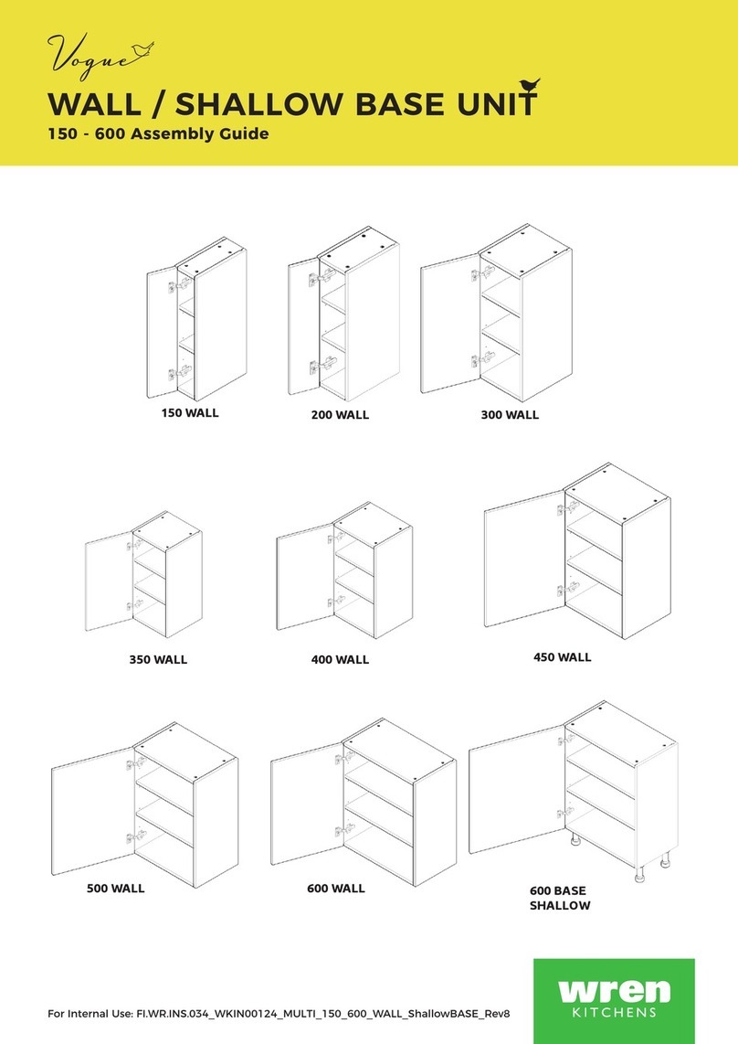
Wren Kitchens

Wren Kitchens BASE UNIT 600 User manual

Wren Kitchens TOWER UNIT 84 Walk in User manual

Wren Kitchens

Wren Kitchens TOWER UNIT 84 Walk in User manual

Wren Kitchens Vogue BASE UNIT 150 Pull Out User manual

Wren Kitchens

Wren Kitchens Vogue BASE UNIT 150 Pull Out User manual

Wren Kitchens BASE UNIT 600 User manual

Wren Kitchens

Wren Kitchens BASE UNIT 600 User manual

Wren Kitchens TOWER UNIT Built-in 2070 x 600 Tall User manual
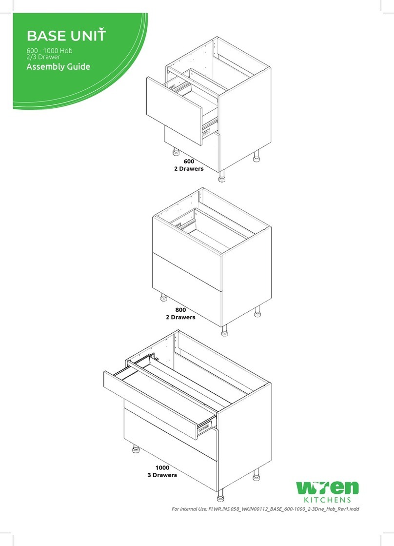
Wren Kitchens

Wren Kitchens TOWER UNIT Built-in 2070 x 600 Tall User manual

Popular Indoor Furnishing manuals by other brands

Night & Day Furniture Poppy Assembly instructions

Night & Day Furniture

Night & Day Furniture Poppy Assembly instructions

Habitat Max II 805826 manual

Habitat

Habitat Max II 805826 manual

XtremeAIR P2025.32 Assembly manual

XtremeAIR

XtremeAIR P2025.32 Assembly manual

Dawn Tuscany AAPS-6001 installation guide

Dawn

Dawn Tuscany AAPS-6001 installation guide

Next JAUG BRONX M76551 Assembly instructions

Next

Next JAUG BRONX M76551 Assembly instructions

ofichairs GENIOUS SMART Assembly instructions

ofichairs

ofichairs GENIOUS SMART Assembly instructions

East West Furniture VEP Assembly instructions

East West Furniture

East West Furniture VEP Assembly instructions

VersaTables PowerLift PLCPUH Assembly instructions

VersaTables

VersaTables PowerLift PLCPUH Assembly instructions

Furniture of America CM7164D Assembly instructions

Furniture of America

Furniture of America CM7164D Assembly instructions

Frontgate Carmel 166379 Assembly instruction

Frontgate

Frontgate Carmel 166379 Assembly instruction

Kvik OU845 manual

Kvik

Kvik OU845 manual

Howdens TOWER UNIT 3 DRAWERS Assembly instructions

Howdens

Howdens TOWER UNIT 3 DRAWERS Assembly instructions

Cypress Hills AXCRGREY06 Assembly instructions

Cypress Hills

Cypress Hills AXCRGREY06 Assembly instructions

OfficeSource PLTCRKB36WF30 Assembly instructions

OfficeSource

OfficeSource PLTCRKB36WF30 Assembly instructions

ETC VORA Assembly

ETC

ETC VORA Assembly

Finori SH2/016 Assembly instructions

Finori

Finori SH2/016 Assembly instructions

STRUCTUBE NELSON Assembly instructions

STRUCTUBE

STRUCTUBE NELSON Assembly instructions

Cooper Lighting Shaper 404 specification

Cooper Lighting

Cooper Lighting Shaper 404 specification

manuals.online logo
manuals.online logoBrands
  • About & Mission
  • Contact us
  • Privacy Policy
  • Terms and Conditions

Copyright 2025 Manuals.Online. All Rights Reserved.