manuals.online logo
Brands
  1. Home
  2. •
  3. Brands
  4. •
  5. Wren Kitchens
  6. •
  7. Indoor Furnishing
  8. •
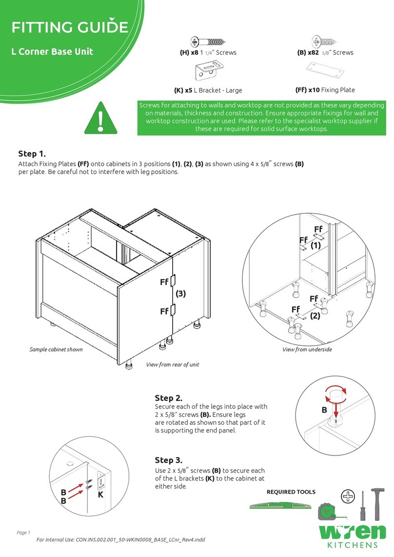
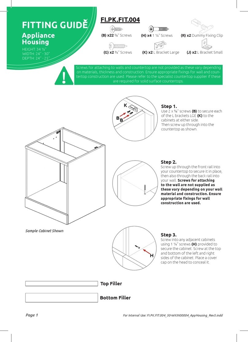
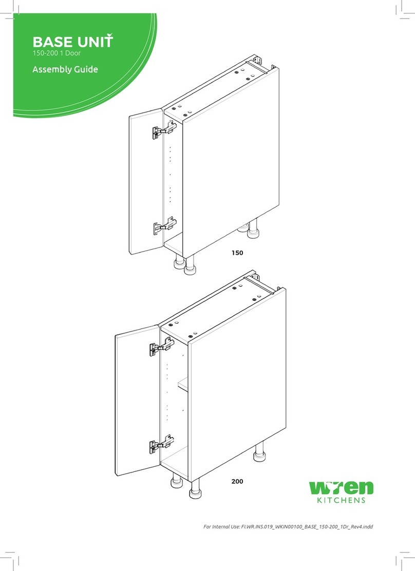
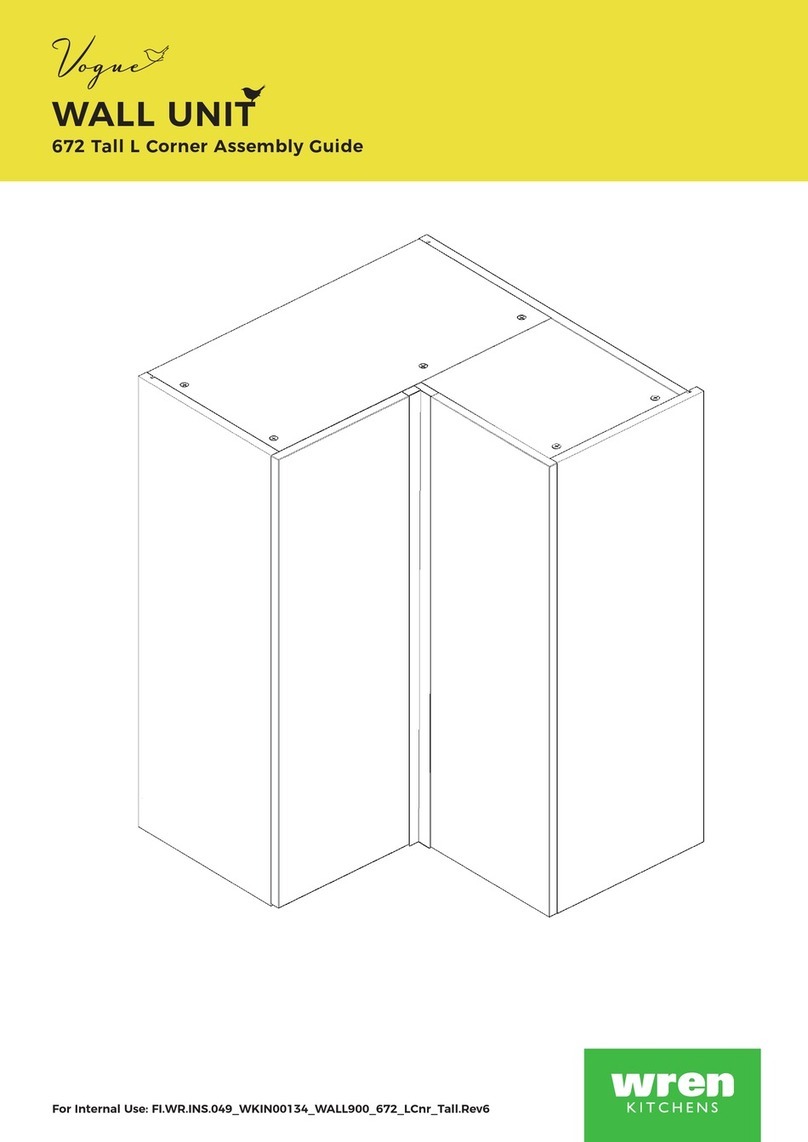
  9. Wren Kitchens Vogue BASE UNIT 972 L Corner User manual

Wren Kitchens Vogue BASE UNIT 972 L Corner User manual

BASE UNIT
972 L Corner Assembly Guide
For Internal Use: FI.WR.INS.024_WKIN00106_BASE_972_LCnr_Rev6.indd
Page 1
BASE UNIT
972 L Corner Assembly Guide
Legs
x9
Panel A
x1 Back Panel
Panel C
x1 Fixed Shelf
Panel B
x3 End Panels
Panel S
x1 2nd
Back Panel
Panel T
x2 Fixed Shelf
Panel E
x2 Rail
Loose Shelf
x1 Large
x1 Small
Frontal
x2 (Packed
Separately)
Corner Post
(Packed
Separately)
REQUIRED TOOLS
NOT to be
used with CAM
DOWEL & CAM
LOCK
Hinge Mounting Bracket
x4 Inc Screws
L Bracket LGE
x2
XL Space Plug
x1
Hinge
x4 Inc Screws
(F) x16
Wooden
Dowel
(G) x12
Cam Dowel
(Expanding)
(H) x12
Cam Lock
(P) x8
45mm Screw
Black
(K) x4
30mm
Screw
(L) x76
15mm
Screw
(N) x2
Door Buer
(Z) x6
Shelf Peg
Plastic
(U) x10
Fixing Plate
Space Plug
x2
BEFORE YOU START
INSTALLATION
SHOULD BE
PERFORMED BY A
COMPETENT
PERSON ONLY.
THIS PRODUCT COULD
BE DANGEROUS
IF INCORRECTLY
INSTALLED
Page 2
For Internal Use: FI.WR.INS.024_WKIN00106_BASE_972_LCnr_Rev6.indd
CARCASE 1
All Cam Locks (H) are to be positioned facing the
outside of the unit carcase, for ease of tightening.
Do NOT use power tools with
cam dowel (G) or cam lock (H)
Dowel (F)
& Cam Dowel (G)
location detail
B
B
E
E
C
B
B
View from underside View from underside
H
G
GH
GG
G
F
F
GG FF FF
B
B
G
GF
F
FF
G
F
F
Step 1.
Seat dowel (F)
into holes in
both end panels (B)
as shown.
Step 2.
Seat cam dowel (G) into
holes in both end panels (B)
as shown.
Seat (G)
cam dowel
into hole as
shown.
Step 3.
Attach panels (C) to panels (B),
using cam dowel (G) (in blue), and
also using dowels (F) (in orange)
in positions as shown.
Step 4.
Insert cam lock (H).
Do NOT tighten until Step 6.
Page 3
BASE UNIT
972 L Corner Assembly Guide
Step 5.
Slide back panel (A) into groove of panels (B).
Once back panel (A) is in position, ensure the
panel is ush & square with the bottom of the
end panels (B)
Step 6.
Hand tighten all cam locks (H), this will
expand the cam dowels (G) and tighten the
unit together.
Step 7.
Secure back panel (A) with 4x 30mm
screws (K) equally spaced at the bottom
of back panel (A) into base panel (C), as
shown.
Ensure you screw into the centre of base
panel (C)
(9mm from the bottom edge).
A
E
C
B
B
A
K
C
B
9mm
Page 4
For Internal Use: FI.WR.INS.024_WKIN00106_BASE_972_LCnr_Rev6.indd
Step 10.
Attach both panels (T) to panel (B), using
cam dowel (G) (in blue) and also using
dowels (F) (in orange) in positions as shown.
Step 11.
Insert cam lock (H) and hand
tighten.
All Cam Locks (H) are to be positioned facing the
outside of the unit carcase, for ease of tightening.
G
G
F
F F G
FG
CARCASE 2
Do not use power tools with
cam dowel (G) or cam lock (H)
B
T
T
Dowel (F)
& Cam Dowel (G)
location detail
B
B
View from underside View from underside
H
G
G
H
B
Step 8.
Seat dowel (F)
into holes in
both end panels (B)
as shown.
Step 9.
Seat cam dowel (G) into
holes in both end panels (B)
as shown.
Seat (G)
Cam Dowel
into hole as
shown.
Page 5
BASE UNIT
972 L Corner Assembly Guide
Step 12.
Secure panel (S) with 4x 45mm screws (P) at the
top and 4x 45mm screws (P) in the bottom, in the
holes provided as shown.
Step 13.
Secure both carcases together using xing
plates (U) with 4 x 15mm screws (L) to each
plate (U). Plates (U) should be positioned
equally spaced as shown.
S
T
T
L
L
L
L
U
U
U
U
UL
P
L
U
P
Page 6
For Internal Use: FI.WR.INS.024_WKIN00106_BASE_972_LCnr_Rev6.indd
Step 15.
Secure each of the legs into place with 4 x 15mm screws
(L) per leg.
Step 14.
Position legs as shown. Ensure legs are rotated
to also provide support to the end panels (B).
L
L
L
L
B
B
C
C
Step 16.
Push leg rmly down into leg base.
Adjust legs to 155mm before turning unit upright. Once in
situ level accordingly.
Front
Front
Leg position diagram
B
B
B
Page 7
BASE UNIT
972 L Corner Assembly Guide
Step 17.
Attach hinge mounting plate onto both end panels (B) as
shown, using screws which are already positioned within the
hinge plates.
Hinge side or sides to be mounted in accordance to
Customer Specic Kitchen Plan.
Carcase 1
Carcase 2
XL
Space
Plug
Space
Plugs
Securing to Adjacent Units
Screw into any side units using the 30mm screws (K) provided to secure to unit. Screw
just to the rear of the hinge plate at the top and bottom of both sides of the unit, place
a cover cap (M) on the head to conceal it.
Worktop
Screw up through the front rail into your worktop to secure it in place.
LL
Secure unit to wall using Space Plugs. Drill 2 pilot holes through the back rail of carcase
1 into the wall, drill 1 pilot hole through the back rail of carcase 2 into the wall and
insert wall plugs. Then unwind Space-Plugs behind carcase 1 and XL Space-Plug behind
carcase 2 until they contact both surfaces. Finally, tighten the screws.
L Brackets
Use 2 x 15mm screws (L) to secure each of the L brackets
to the units at either side. Then screw up through into the
worktop as shown.
126mm
126mm
94mm
94mm
B
from base
from top
K
Screws for attaching to walls and worktop are not provided as these vary
depending on materials, thickness and construction. Ensure appropriate
xings for wall and worktop construction are used. Please refer to
the specialist worktop supplier if these are required for solid surface
worktops.
Page 8
For Internal Use: FI.WR.INS.024_WKIN00106_BASE_972_LCnr_Rev6.indd
Step 19.
Align corner post to frontal. Equally space 2 xing plates (U)
to the back of frontal & corner post. Ensure a 4mm gap is
maintained between frontal & post once xed together. Screw in
place using 4 x 15mm screws (L) per xing plate (U).
Hinge Plates
Step 18.
Insert hinge in top & bottom holes as shown below.
Step 20.
Secure hinges by tightening
2 x screws with hinge dowels
attached. These are already
positioned within the hinges.
Step 21.
Attach the door to unit where required.
To attach door, clip hinge onto hinge plate and click to
secure.
Hinge Cover Caps
Step 23.
Fit cover caps to hinge.
Adjust Soft close to suit.
Step 22.
Adjust hinge to suit. As shown below.
To adjust hinge using
a screw driver, tighten
or loosen as required at
points 1 & 2.
Point 1- In - Out
Point 2- Left - Right
12
FRONTAL
HINGE
ADJUSTMENT
View from inside of Unit
To release door,
pull catch as shown,
to release hinge from
the hinge plate.
The top and bottom
hinges MUST be
adjusted to the SAME
STRENGTH.
To Move the
hinge up/down,
loosen screws
A + B,
Manoeuvre
the door, then
re-tighten the
screws
A
B
Page 9
BASE UNIT
972 L Corner Assembly Guide
Page 10
For Internal Use: FI.WR.INS.024_WKIN00106_BASE_972_LCnr_Rev6.indd

Other Wren Kitchens Indoor Furnishing manuals
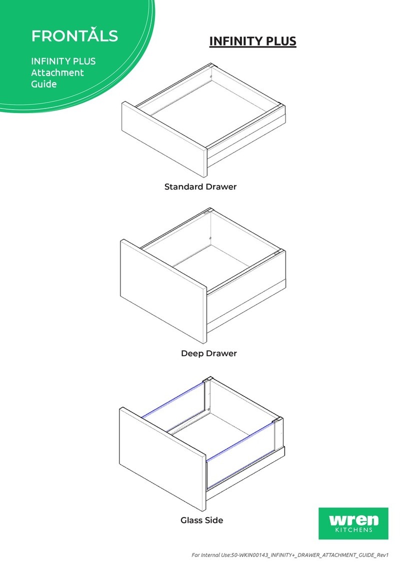
Wren Kitchens BASE UNIT 1000 User manual

Wren Kitchens

Wren Kitchens BASE UNIT 1000 User manual

Wren Kitchens BASE UNIT 600 User manual

Wren Kitchens

Wren Kitchens BASE UNIT 600 User manual

Wren Kitchens WALL UNIT 360 x 1000 User manual

Wren Kitchens

Wren Kitchens WALL UNIT 360 x 1000 User manual

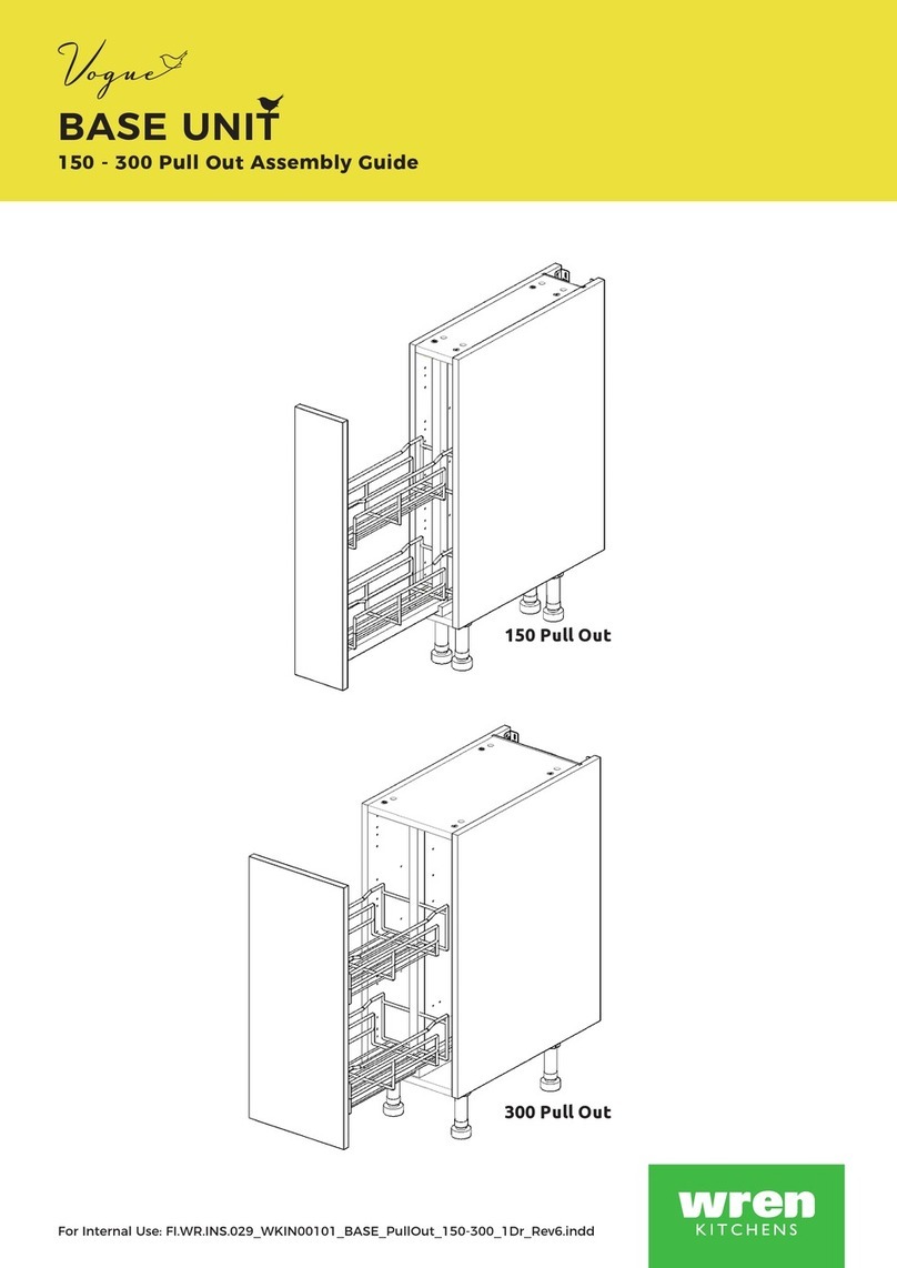
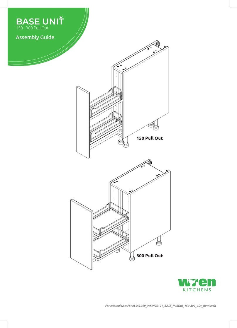
Wren Kitchens 150 Pull Out User manual

Wren Kitchens

Wren Kitchens 150 Pull Out User manual

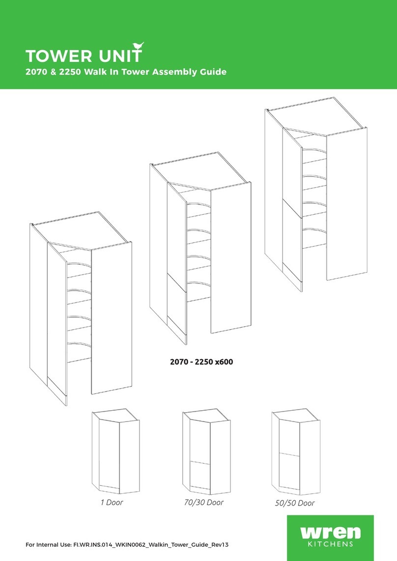
Wren Kitchens TOWER UNIT 84 Walk in User manual

Wren Kitchens

Wren Kitchens TOWER UNIT 84 Walk in User manual

Wren Kitchens Industrial Island User manual

Wren Kitchens

Wren Kitchens Industrial Island User manual

Wren Kitchens BASE UNIT 600 User manual

Wren Kitchens

Wren Kitchens BASE UNIT 600 User manual

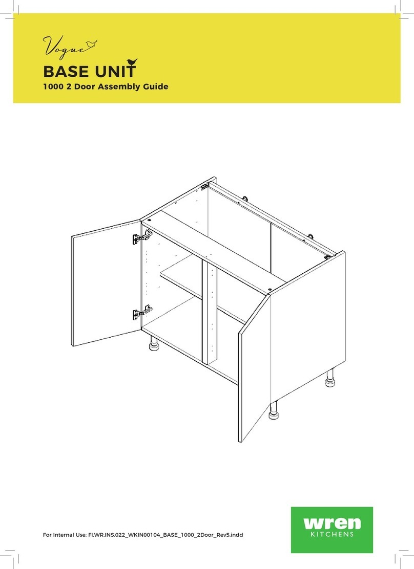
Wren Kitchens Vogue BASE UNIT 1000 2 Door User manual

Wren Kitchens

Wren Kitchens Vogue BASE UNIT 1000 2 Door User manual

Wren Kitchens FRONTALS Parts list manual

Wren Kitchens

Wren Kitchens FRONTALS Parts list manual

Wren Kitchens 1000 Base Shallow User manual

Wren Kitchens

Wren Kitchens 1000 Base Shallow User manual

Wren Kitchens Vogue WALL UNIT 150 Tall 1 Door User manual

Wren Kitchens

Wren Kitchens Vogue WALL UNIT 150 Tall 1 Door User manual

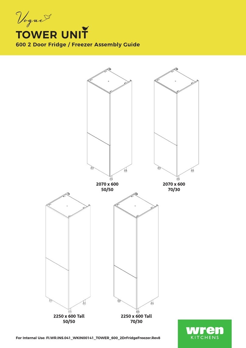
Wren Kitchens TOWER UNIT 2070 x 600 50/50 User manual

Wren Kitchens

Wren Kitchens TOWER UNIT 2070 x 600 50/50 User manual

Wren Kitchens 2070 User manual

Wren Kitchens

Wren Kitchens 2070 User manual

Wren Kitchens Vogue BASE UNIT 500 3 Drawer User manual

Wren Kitchens

Wren Kitchens Vogue BASE UNIT 500 3 Drawer User manual

Wren Kitchens WALL UNIT 672 L Corner User manual

Wren Kitchens

Wren Kitchens WALL UNIT 672 L Corner User manual

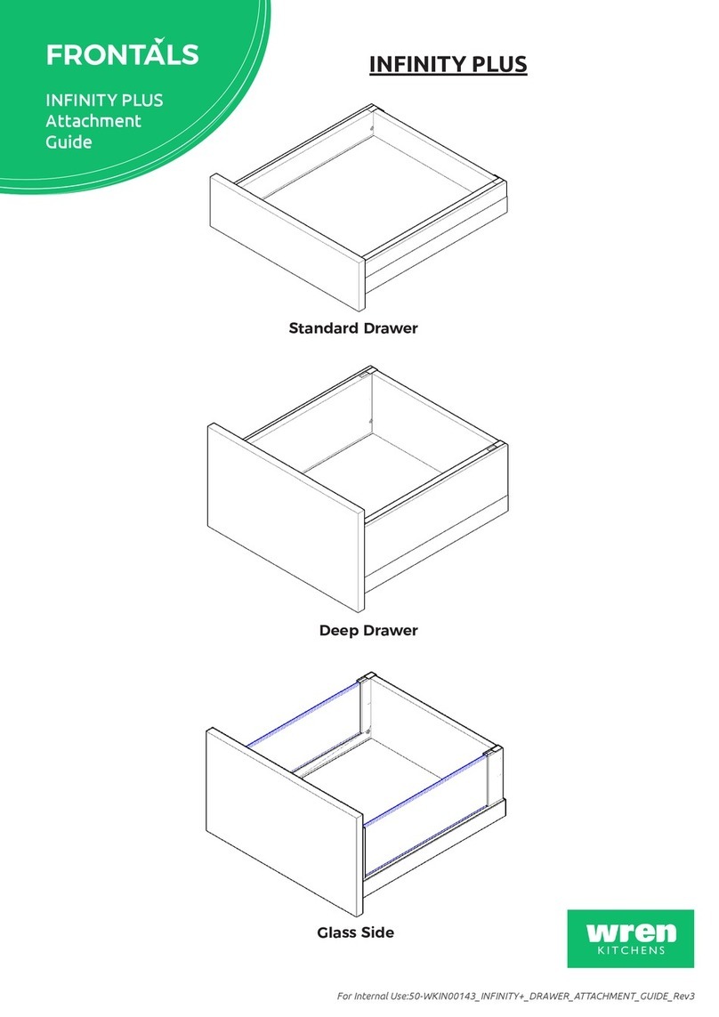
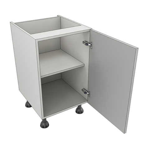
Wren Kitchens INFINITY PLUS Standard Drawer User manual
Wren Kitchens

Wren Kitchens INFINITY PLUS Standard Drawer User manual

Wren Kitchens Vogue WALL UNIT 672 Tall L Corner User manual

Wren Kitchens

Wren Kitchens Vogue WALL UNIT 672 Tall L Corner User manual

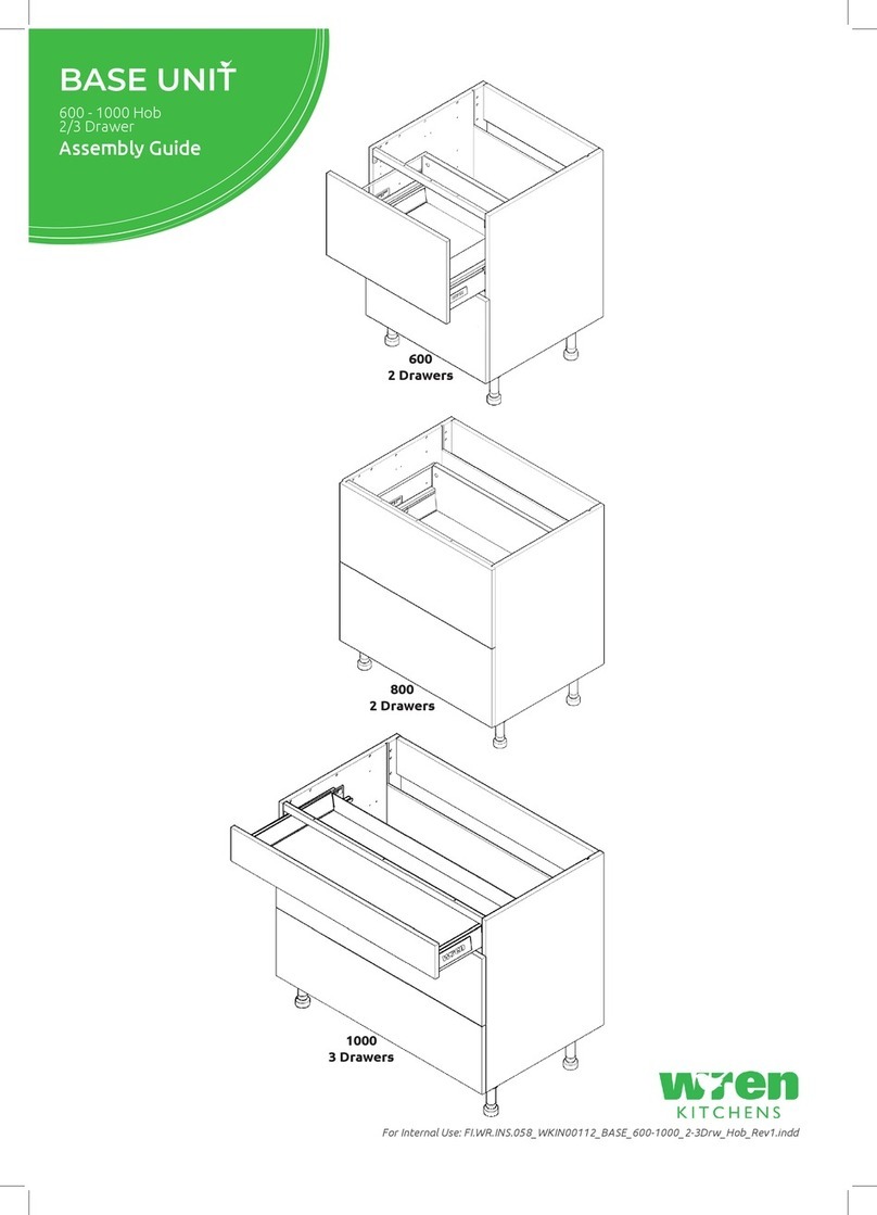
Wren Kitchens Vogue BASE UNIT 600 2 Drawer User manual

Wren Kitchens

Wren Kitchens Vogue BASE UNIT 600 2 Drawer User manual

Wren Kitchens BASE UNIT 600 Built Under Oven Housing User manual

Wren Kitchens

Wren Kitchens BASE UNIT 600 Built Under Oven Housing User manual

Wren Kitchens WALL UNIT 672 L Corner User manual

Wren Kitchens

Wren Kitchens WALL UNIT 672 L Corner User manual

Wren Kitchens BASE UNIT 600 User manual

Wren Kitchens

Wren Kitchens BASE UNIT 600 User manual

Wren Kitchens Vogue BASE UNIT 150 WALL User manual

Wren Kitchens

Wren Kitchens Vogue BASE UNIT 150 WALL User manual

Wren Kitchens 2070 User manual

Wren Kitchens

Wren Kitchens 2070 User manual

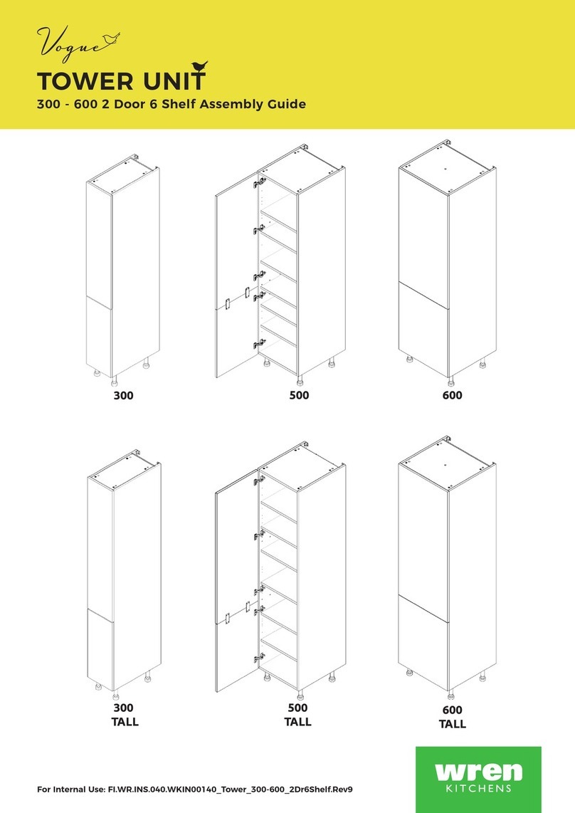
Wren Kitchens Vogue BASE UNIT 1000 2 Door User manual
Wren Kitchens

Wren Kitchens Vogue BASE UNIT 1000 2 Door User manual

Popular Indoor Furnishing manuals by other brands

Triarch 34115 Assembly instructions

Triarch

Triarch 34115 Assembly instructions

MACMILANO CAPITAN MCM022002 Series quick start guide

MACMILANO

MACMILANO CAPITAN MCM022002 Series quick start guide

Steelcase Regard Tablet installation guide

Steelcase

Steelcase Regard Tablet installation guide

Garden Trading Luccombe Sofa Set Assembly instructions

Garden Trading

Garden Trading Luccombe Sofa Set Assembly instructions

Whittier Wood Furniture McKenzie 1372GACI Assembly instructions

Whittier Wood Furniture

Whittier Wood Furniture McKenzie 1372GACI Assembly instructions

Furniture of America Ismay CM-OT1847-BC-6PK Assembly instructions

Furniture of America

Furniture of America Ismay CM-OT1847-BC-6PK Assembly instructions

Next SLOANE 437640 Assembly instructions

Next

Next SLOANE 437640 Assembly instructions

physa PESSAC GREY user manual

physa

physa PESSAC GREY user manual

Furniture of America CM-DK5674CNR Assembly instructions

Furniture of America

Furniture of America CM-DK5674CNR Assembly instructions

OYPLA Home 3879 user manual

OYPLA Home

OYPLA Home 3879 user manual

Bliss BHC-412F-3 manual

Bliss

Bliss BHC-412F-3 manual

Vivo DESK-TOP3B instruction manual

Vivo

Vivo DESK-TOP3B instruction manual

Lightolier Calculite CFL Lensed Downlight 8096 manual

Lightolier

Lightolier Calculite CFL Lensed Downlight 8096 manual

Kewaunee DCLT10R2436 Assembly instructions

Kewaunee

Kewaunee DCLT10R2436 Assembly instructions

BLACK RED WHITE LOFT B156-REG1D1S/60 Assembly instructions

BLACK RED WHITE

BLACK RED WHITE LOFT B156-REG1D1S/60 Assembly instructions

Woood JELLE manual

Woood

Woood JELLE manual

BLACK RED WHITE LARGO PKOM4S/11 manual

BLACK RED WHITE

BLACK RED WHITE LARGO PKOM4S/11 manual

Walker Edison AF44MOL2DR Assembly instructions

Walker Edison

Walker Edison AF44MOL2DR Assembly instructions

manuals.online logo
manuals.online logoBrands
  • About & Mission
  • Contact us
  • Privacy Policy
  • Terms and Conditions

Copyright 2025 Manuals.Online. All Rights Reserved.