Xtool IP608 User manual

Shenzhen Xtooltech Intelligent Co., LTD
User Manual
IP608 Smart Diagnostic System
Version 3.2
Revise date 2022/11

I
Please read this user manual carefully before using the IP608 Smart Diagnostic System, referred to as the “Scan Tool”
throughout this document. When reading the manual, please pay attention to the words “Note” or “Caution”, and read them
carefully for appropriate operation.
OPERATION INSTRUCTIONS
For safe operation, please follow the instructions below:
⚫Keep the device away from heat or fumes when in use.
⚫If the vehicle battery contains acid, please keep your hands and skin or fire sources away from the battery during
testing.
⚫The exhaust gas of the vehicle contains harmful chemicals. Please ensure adequate ventilation.
⚫Do not touch the vehicle cooling system components or exhaust manifolds when the engine is running due to the high
temperatures reached.
⚫Make sure the car is securely parked, Neutral is selected or the selector is at the P or N position to prevent the vehicle
from moving when the engine starts.
⚫Make sure the (DLC) Diagnostic Link Connector is functioning properly before starting the test to avoid damage to the
Diagnostic Computer.
⚫Do not switch off the power or unplug the connectors during testing. Doing so may damage the ECU (Electronic
Control Unit) and/or the Diagnostic Computer.
CAUTIONS!
⚫Avoid shaking, dropping or dismantling the scan tool as it may damage the internal components.
⚫Use only your fingertips to touch the LCD screen. Hard or sharp objects may damage the scan tool.
⚫Do not use excessive force;
⚫Do not expose the screen to strong sunlight for a long period.
⚫Please keep the scan tool away from water and moisture.
⚫Store and use the scan tool only within the temperature ranges identified in the Technical Specifications section.
⚫Keep the unit away from strong magnetic fields.
AFTERSALES-SERVICES
XTOOL strives to provide best-in-class support!
Tel: +86 755 21670995 or +86 755 86267858 (China)
Official Website: www.xtooltech.com | www2.xtooltech.com (Alternate sites)

i
CONTENT
OPERATION INSTRUCTIONS ............................................................................................................................ I
CAUTIONS!.......................................................................................................................................................... I
AFTERSALES-SERVICES .................................................................................................................................. I
CONTENT ............................................................................................................................................................ I
1. GENERAL INTRODUCTION..................................................................................................................... 4
2. GETTING STARTED................................................................................................................................. 4
Connecting Power............................................................................................................................................................4
Activation.........................................................................................................................................................................5
3. DIAGNOSTIC ............................................................................................................................................ 7
Vehicle Connection..........................................................................................................................................................7
Beginning Diagnostic Testing ..........................................................................................................................................8
Vehicle Selection.................................................................................................................................................................................... 8
Diagnosis functions.............................................................................................................................................................................10
4. SPECIAL FUNCTIONS ........................................................................................................................... 15
ABS BLEEDING.............................................................................................................................................................15
OIL RESET....................................................................................................................................................................18
EPB................................................................................................................................................................................20
THROTTLE....................................................................................................................................................................21
SAS................................................................................................................................................................................21
BMS RESET..................................................................................................................................................................23
INJECTOR CODING......................................................................................................................................................24
DPF REGENERATION..................................................................................................................................................26
TPMS RESET................................................................................................................................................................29
5. SETTINGS............................................................................................................................................... 32
Language.......................................................................................................................................................................32
Units...............................................................................................................................................................................32

ii
My Workshop Info..........................................................................................................................................................33
Firmware Information.....................................................................................................................................................33
About .............................................................................................................................................................................34
6. REPORT.................................................................................................................................................. 34
Report............................................................................................................................................................................34
Replay............................................................................................................................................................................36
File Manager..................................................................................................................................................................36
7. UPDATE & FACTORY RESET............................................................................................................... 37
Update...........................................................................................................................................................................37
Factory Reset ................................................................................................................................................................37
8. FAQ.......................................................................................................................................................... 39
Q1: Failed to generate Diagnostic report.......................................................................................................................39
Q2: How to print a Diagnostic report..............................................................................................................................39
Q3: Failed to extract files...............................................................................................................................................39
Q4: Mailbox supported...................................................................................................................................................39
Q5: How to make an appointment for remote support ...................................................................................................40
Q6: How to generate and upload diagnostic log files.....................................................................................................40
Q7: How to switch language..........................................................................................................................................40
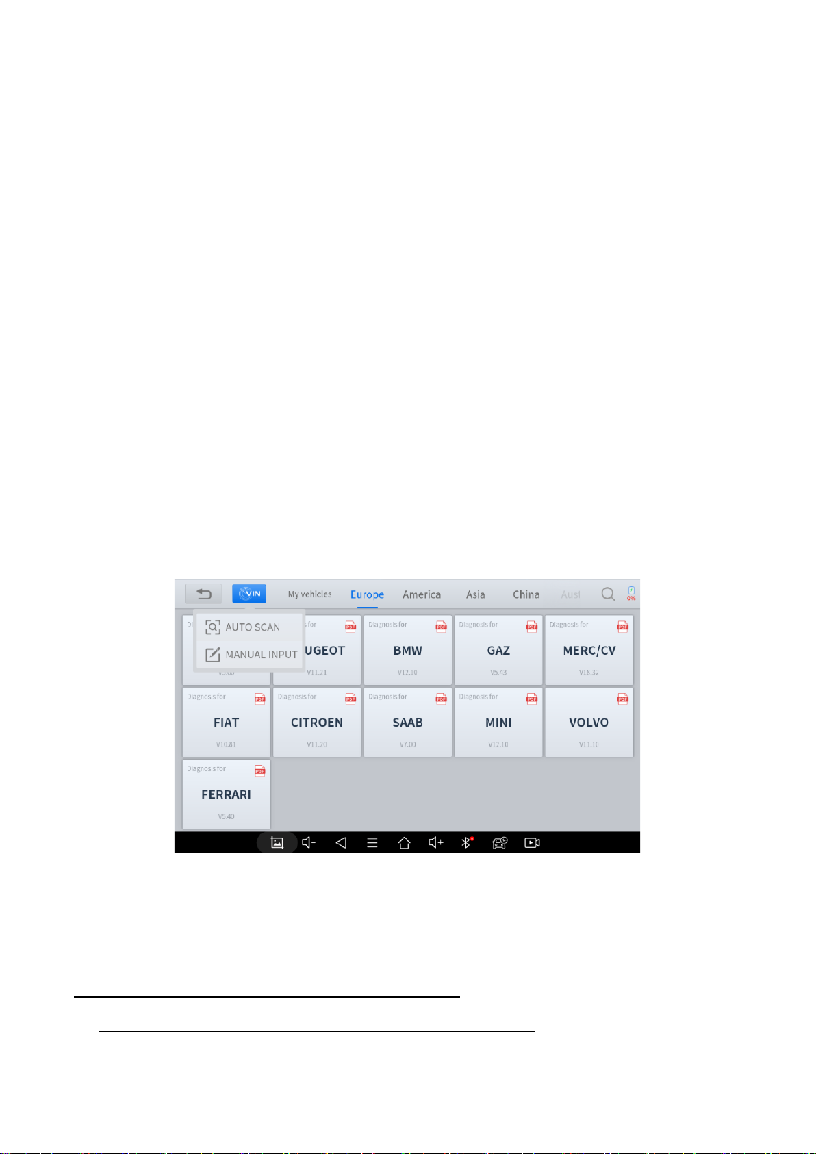
Q8: Failed to diagnose vehicle.......................................................................................................................................40
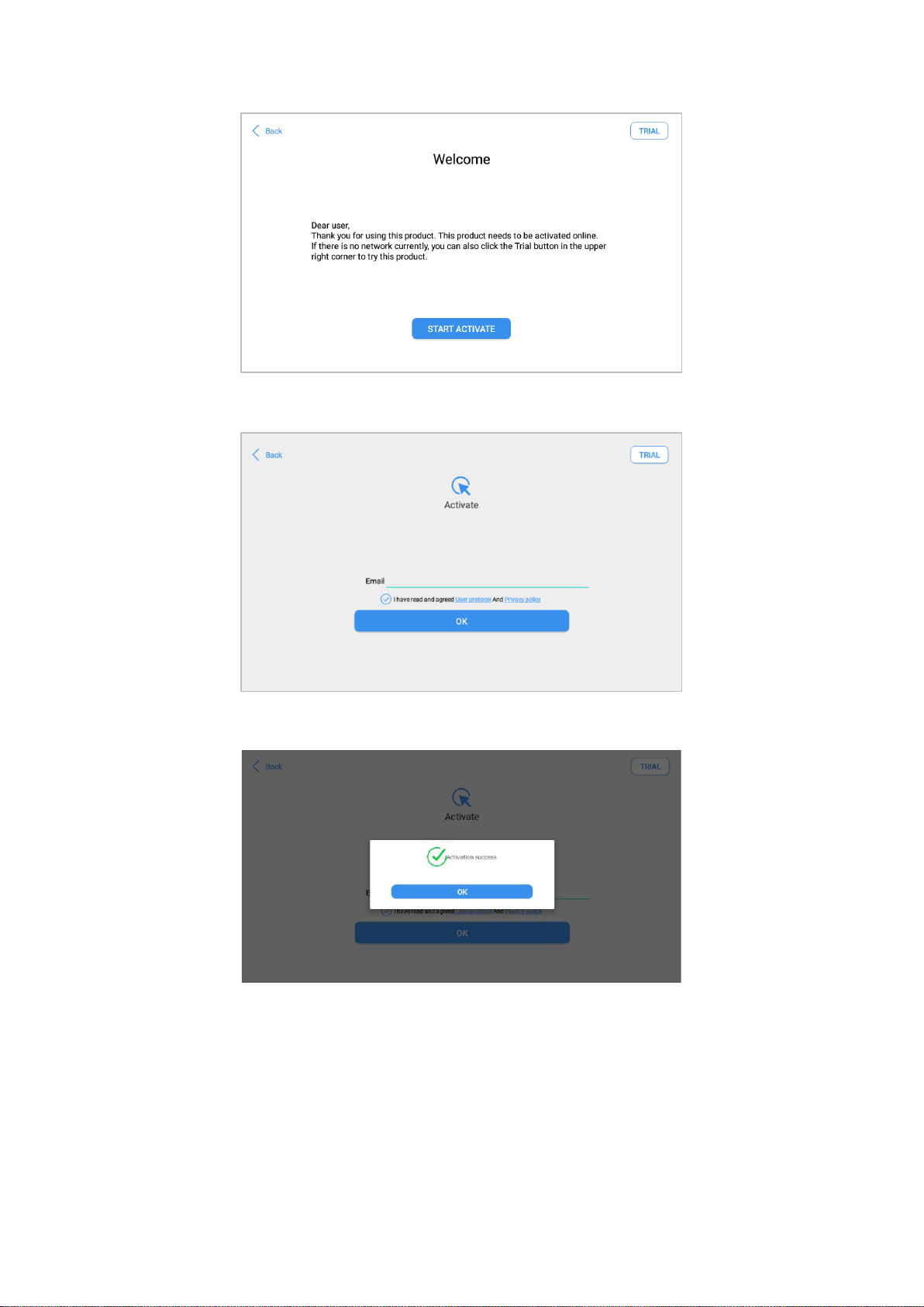
Q9: Failed to activate or register....................................................................................................................................40
Q10: Failed to turn on when charging............................................................................................................................40
Q11: Failed to open the Diagnostic app......................................................................................................................... 40
Q12: Can’t receive the email after sharing the diagnostic report ...................................................................................41
9. REMOTE ASSISTANCE ......................................................................................................................... 41
10. WARRANTY & SERVICES..................................................................................................................... 42
11. APPENDIX............................................................................................................................................... 42
DTC Status....................................................................................................................................................................42
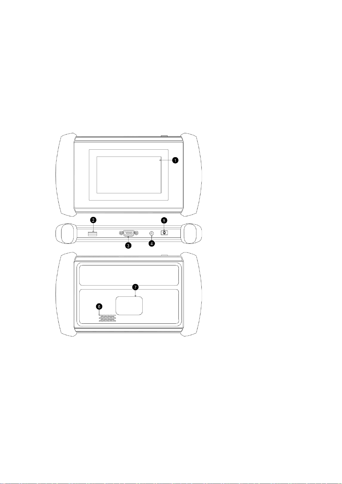
Button Description..........................................................................................................................................................43

iii
Function Buttons..................................................................................................................................................................................43
Navigation Buttons .............................................................................................................................................................................43
Notification Bar .................................................................................................................................................................................... 44
Compliance Information.................................................................................................................................................45
FCC Compliance ..................................................................................................................................................................................45
CE..............................................................................................................................................................................................................45
UKCA........................................................................................................................................................................................................45
Trademarks....................................................................................................................................................................47
Copyright .......................................................................................................................................................................47

4
1. GENERAL INTRODUCTION
The XTOOL IP608 smart diagnostic system (referred to as the “Scan Tool”) is an advanced scanning tool based on the
Android operating system. It supports multiple languages and is suitable for different countries and regions. The advantage
of this OBD-II (On-Board Diagnostics version 2) scanner is its comprehensive functions and its ability to quickly provide the
user with more accurate diagnostic information. Some of the diagnostic functions include:
•Full system Diagnostics function
•Full OBD-II functions
•8 reset functions: ABS (Anti-block system) bleed/ Oil light reset / EPB (Electronic Parking Brake) reset / SAS
(Steering Angle Sensors) reset / BMS matching / Injector coding / DPF Regeneration/ TPMS reset
1. 5-inch Touch Screen
2. UBS Port - Available for
charging and data transfer
3. DB15 Port
4. DC Charger Port –
Reserved, compatible with
12V DC chargers
5. Power Button
6. Speaker
7. Name Plate
2. GETTING STARTED
CONNECTING POWER
The scan tool may need to be charged before first use. Confirm the proper power adapter (either 120 VAC North American
or 240 VAC European version) is attached to the AC/DC charger.
Plug the AC/DC charger into a wall outlet
Plug the USB cable into the AC/DC charger and also into the scan tool’s USB charging port.

5
!
Note: When connected to the OBD port, the device can be automatically charged via the car battery. The scan
tool can standby for one day in sleep mode and up to 3 months when power off. It is recommended to switch off
your Scan Tool after use!
ACTIVATION
After first-time users press and hold the power button to turn on the system, the system will automatically enter the guided
process and request the user to select the language for the operating system.
After setting the system language, click Next to enter the Wi-Fi connection page, as shown below:
Select a network to connect to on the Wi-Fi connection page. You need to enter the Wi-Fi password to establish Wi-Fi
connectivity and the activation page, as shown in the figure below. You can also click the "Trial" button in the upper right
corner to try it out before activation. However, activation is highly recommended to take advance of any new online software
updates.

6
Click Start Activation to enter the activation page, as shown below:
A pop-up window showing Activation Success indicates that you have completed the first boot setup,
Click OK to enter the diagnostic system and start using the device.

7
3. DIAGNOSTIC
The diagnostic application can read ECU information, read and clear DTC (Diagnostic Trouble Codes) and check live data
and freeze frame data. The Diagnostic application can access the ECU of various vehicle control systems, including the
Engine, Transmission, Anti-lock Braking System (ABS), Airbag Safety Restraing System (SRS), Electronic Parking Brake
system (EPB) and perform many types of actuation tests.
VEHICLE CONNECTION
The scan tool must be connected to the vehicle’s OBD-II port so that the tablet can establish correct vehicle communication.
Please perform the following steps:
1 Turn on the tablet
2 Connect vehicle and tablet via the main test cable
3 Switch on the ignition and tap on the Diagnostic application to start your diagnosis.
The connection method is shown in the figure below:
1. Vehicle
2. Main Cable (DB15
to OBD16)
3. Tablet
⚫Precautions for Diagnosis
1. The voltage range on the car: +9~+18V DC;
Note: Please make sure all the cables are connected tightly; The vehicle’s DLC is not always located under
the dash; for the location of the DLC, please refer to the vehicle’s user manual.

8
2. When testing some special functions, the operator must operate according to the prompts and meet the test conditions.
For some models [special functions], the conditions that need to be met are: engine water temperature 80 ℃~105 ℃, turn
off headlights and air conditioners, keep the accelerator pedal in the released position, etc.;
3. The electronic control systems of differentmodels are very complicated. If you encounter situations where it is impossible
to test or a large amount of test data is abnormal, you can search for the ECU of the vehicle and select the menu for the
model on the ECU nameplate;
4. If the vehicle type or electronic control system to be tested is not found in the diagnostic function, please upgrade the
vehicle diagnostic software to the latestversion using the Updates menu or consult the XTOOL technical servicedepartment;
5. Only wiring harnesses provided by XTOOL and designed for the scan tool are permitted to be used with this scan tool to
avoid damage to the vehicle or the scan tool;
6. When running a Diagnostics function, it is forbidden to shut down the scan tool directly. You should cancel the task before
returning to the main interface and then shutting down the scan tool.
BEGINNING DIAGNOSTIC TESTING
After the tablet device is properly connected to the vehicle, you could start the vehicle diagnosis.
VEHICLE SELECTION
The scan tool supports the following 3 ways to access the smart diagnostics system.
⚫AUTO SCAN
⚫MANUAL INPUT
⚫SELECT VEHICLE BY AREA
Click the VIN button in the upper left corner and then choose to enter the vehicle diagnosis through either AUTO SCAN or
MANUAL INPUT.
AUTO SCAN: It supports the automatic reading of vehicle VIN code. You also can tap on the button “AUTO SCAN” on the
diagnosis system entrance to use this function. Please make sure that the car and the device are well connected before
using this function.
If your model is not recognized, please try the following steps:
①
UPDATE all software, and check whether the APP is updated in [Settings]

9
②
Please click Diagnosis on the main menu to enter the selection menu, manually select the engine system to
read the ECU information, and confirm whether the VIN can be read.
③
Contact the XTOOL technical team to provide the VIN code to confirm whether the model supports automatic
identification of VIN.
MANUAL ENTER: It supports manual input of car VIN code. When entering the VIN code manually, make sure that the 17
characters entered are correct to ensure accurate test results.
⚫SELECT VEHICLE BY AREA
In addition to the above 3 methods, you can also choose a car brand by selecting the appropriate region at the top of the
screen. You can select the vehicle model that needs to be diagnosed according to the area, as shown below:
OBD-II supports reading the related fault codes of the Powertrain Control Module (PCM);
DEMO, a demonstration program; Click this button to experience and learn the operation processes of the diagnostic
function
Some models provide multiple entry methods in the sub-menu, including:
⚫Automatic Detection
⚫Manual Selection
⚫System Selection

10
Automatic Detection will automatically identify the vehicle's VIN code, and then read the information of your target
diagnostic object. If you choose "Manual selection", then you can continue to select the vehicle brand, year, and model of
the vehicle in the sub-menu to diagnose the vehicle. Enter "System Selection", you can also diagnose the vehicle according
to the system according to your needs after selecting the model.
DIAGNOSIS FUNCTIONS
Diagnostics functions supported by the scan tool are listed below:
⚫Read ECU Information
⚫Read/Clear Trouble Code
⚫Read Live Data
⚫Freeze Frame
⚫READ ECU INFORMATION
This function is to read ECU version information and is the equivalent of "System Identification" or "System Information”
in some electroniccontrol systems. These equivalent termsall refer to reading ECU-related software andhardware versions,
models and production date of diesel engines, part numbers, etc. This information is helpful when recording maintenance
records and ordering new parts

11
⚫READ TROUBLE CODE
In the process of diagnosis, if the device shows “System is OK”or “No Trouble Code”, it means there is no related trouble
code stored in ECU or some troubles are not under the control of ECU. Most troubles are mechanical system troubles or
executive circuit troubles. It is also possible that the signal of a sensor may be inaccurate but within limits, which can be
examined using Live Data.
⚫CLEAR TROUBLE CODE
It allows for clearing current and historical trouble codes stored in the ECU memory, under the premise that all the troubles
have been resolved.
Some troubles are immediately detected by the ECU with the key in the run position and without the engine running. Other
troubles are not detected until very specific test conditions are met such as engine coolant temperature within a range,
speed within a range for a duration of time, throttle percentage within a range, etc.
If the trouble codes are erased when the trouble remains unresolved, the trouble code will reappear in the ECU the next
time the ECU performs the specific diagnostic test for that trouble.
If the trouble is resolved but there is a stored trouble code, sometimes the ECU will detect the resolution and clear the
trouble code or more likely, classify it as “historical” trouble.
If the trouble is resolved and the user clears the trouble codes, the trouble history will be cleared.
If the user intends to have another colleague or mechanic investigate the problem, it is not recommended for the user to
clear the trouble code since doing so may erase information helpful to others who may investigate the issue.
⚫READ LIVE DATA

12
Real-time information about various sensors is called “Live Data”. Live Data includes parameter identifications (PIDs) of
the running engine such as oil pressure, temperature, engine speed, fuel oil temperature, coolant temperature, intake air
temperature, etc. Based on these parameters, we can predict directly where the problem lies, which helps to narrow the
scope of maintenance. For some vehicles, during their actual operation, the problems such as performance characteristics
or sensitivity reduction, can be evaluated using live data.
Click the magnifying glass on the top right, you can search for related PIDs based on keywords
⚫Custom
The scan tool includes support to select and show multiple PIDs. Click Display All to display all PIDs
⚫Combine

13
The scan tool includes support to select multiple PIDs and click Combine to combine different graphs into one chart.
⚫Data recording
The scan tool supports recording the current data values in the form of text. You can view the recorded files in
Reports->Data Replay.
⚫Pause
Click this button to pause the recording timeline
⚫FREEZE FRAME
When the signal of the sensor is abnormal, the ECU will save the data at that moment of failure to form a freeze-frame. It is
usually used to analyze the reasons that may lead to component(?) failures.

14
The live data items supported by vehicles of different brands are not the same, so the freeze frames displayed when
diagnosing vehicles of different brands may also be different. Some vehicles may not have the option of a freeze-frame
which means that the model does not support this function.
Take Renault Duster ii ph as an example. After selecting the system to enter the lower freeze frame menu, the device will
list all the fault codes under the system.
Users can click on a fault code, such as DF1068 to view the freeze frame recorded by the car when the fault code occurs,
including context when the fault appeared, and current context and additional data.
Context when fault appeared: record the live data when fault appeared to help the user to know the vehicle status. *Some
vehicles don't support this function; users will get a prompt when they click the menu.
Current context: Displays the current live data stream associated with the DTC
Additional data: record other data related to the fault

15
4. SPECIAL FUNCTIONS
The Scan Tool supports 9 commonly used special reset functions, allowing you to quickly access your vehicle system for
various scheduled services, maintenance, and reset performance. These functions often eliminate the need to reset codes
after resolving common problems. Since XTOOL is continuously developing, the manual may not include all of the latest
special functions that are available for download. This user manual lists some of the commonly used special reset services
for your reference.
ABS BLEEDING
Anti-Lock Braking System keeps the tires from locking up immediately when there are brakes. Keeping ABS in good
condition can give full play to the effectiveness of the brakes, shorten the braking time and distance, prevent the vehicle
from skidding and tailing during emergency braking, ensure good driving stability and steering maneuverability, and avoid
violent friction between the tires and the ground to reduce tire wear. When the ABS contains air, the ABS bleeding function
must be performed to bleed the brake system to restore ABS brake sensitivity.
ABS Bleeding can be performed in the following cases:
⚫replace the rear brake distributor pump or the front brake distributor pump. 2.
⚫Severe brake fluid shortage
⚫change the brake fluid
The operation guidelines of the ABS Bleeding function are shown as below:
1. Read the operating instructions and precautions that appear on the screen carefully before performing the operation
to ensure that the equipment and car are in the correct condition
2. Attach bleeder bottle to the left rear bleeder screw.
3. Open the left rear bleeder screw.

16
4. When ready, click "OK" to enter the bleed procedure, and pumping the brake pedal continuously with steady applies
every 2 seconds during the entire procedure
5. Continue pumping the brake pedal, when air bubbles are no longer visible, select OK to enter next bleed procedure
for left front wheel

17
6. Repeat the operation 3 times to complete the bleed procedure for the left front wheel, right front wheel and right rear
wheel in turn.
7. Stop pumping the brake pedal, and close the right rear bleeder screw
8. Click OK to complete the entire bleed procedure

18
Caution
⚫The ABS pump screw needs to be unscrewed
⚫Brake fluid will be under pressure during this process. Secure the bleed hose and open bleeder screws slowly
⚫Some vehicles do not support automatic bleeding, but manually bleeding
OIL RESET
The scan tool can be used to reset the engine oil life system, which calculates the optimum oil life change interval based on
the vehicle’s driving conditions and climate. The oil life reminder must be reset each time the oil is changed so that the
system can calculate when the next oil change is required.
This function can be performed in the following cases:
⚫If the service lamp is on, you must provide service for the car. After service, you need to reset the driving mileage or
driving time so that the service lamp turns off and the system enables the new service cycle.
⚫After changing engine oil or electric appliances that monitor oil life, you need to reset the service lamp.
The operation guidelines of the Oil Reset function are shown as below:
1. Enter the Oil Reset menu and choose relevant models according to the vehicle being tested.
2. Follow the instructions displayed that are specific to the vehicle and press OK after completing the instructions shown.
3. Enter Maintenance mileage reset menu.
4. Click INPUT and enter a reasonable value of remaining oil life and press OK.
Table of contents
Other Xtool Diagnostic Equipment manuals