Constant Color
To select Constant Color, press the ENTER button to confirm. Use the UP/DOWN button to select
No or Yes, press the ENTER button to store. Press the MENU button back to the last menu or let
the unit idle 30 seconds to exit menu mode.
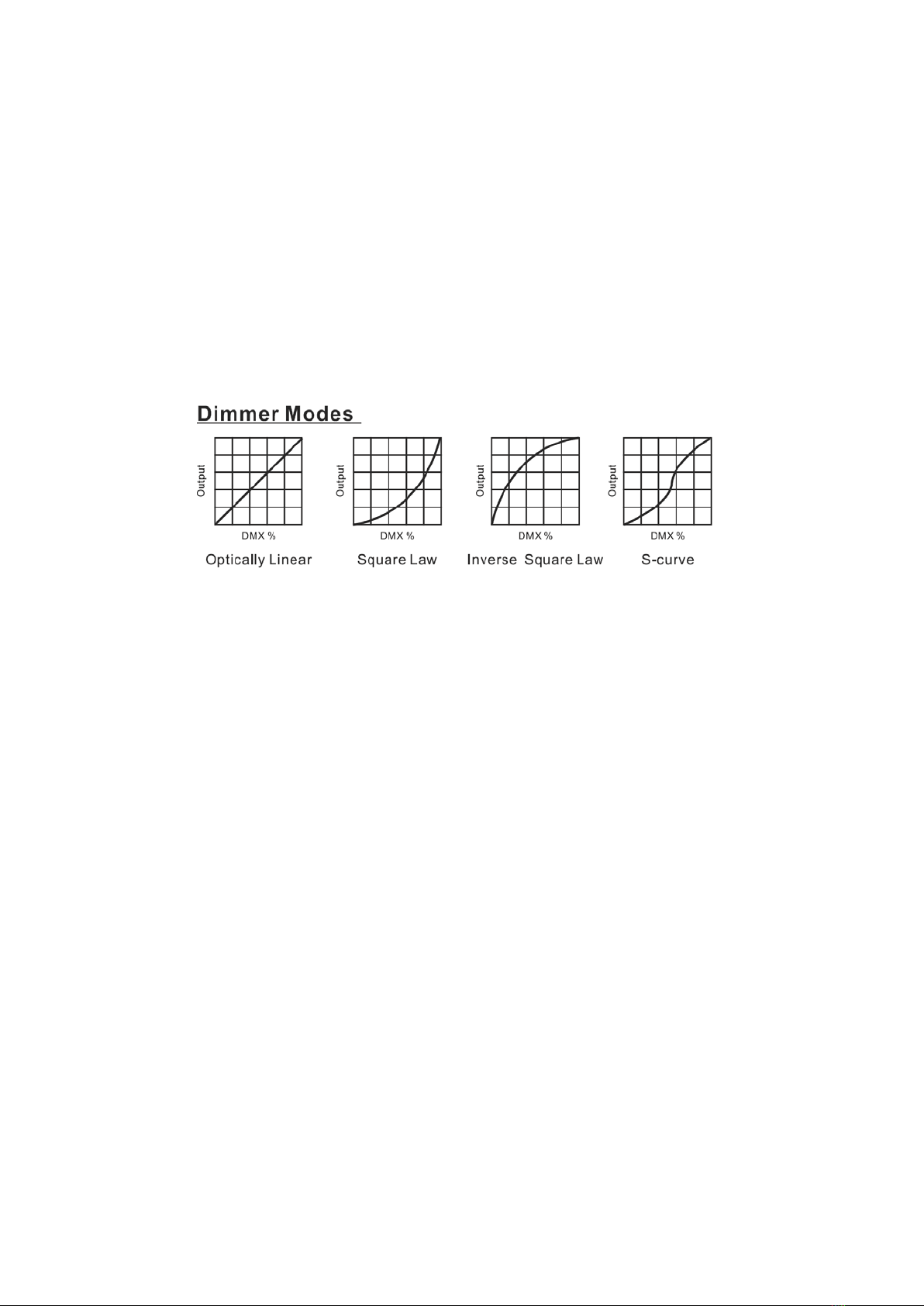
Dimmer Curve
To select Dimmer Curve, press the ENTER button to confirm. Use the UP/DOWN button to select
Optically Linear, Square Law, Inverse Square Law or S-Curve, press the ENTER button to store.
Press the MENU button back to the last menu or let the unit idle 30 seconds to exit menu mode.
Optically Linear:The increase in light intensity appears to be linear as DMX value is increased.
Square Law: Light intensity control is finer at low levels and coarser at high levels.
Inverse Square Law:Light intensity control is coarser at low levels and finger at high levels.
S-Curve: Light intensity control is finger at low levels and high levels and coarser at medium levels.
Dimmer Speed
To select Dimmer Speed, press the ENTER button to confirm. Use the UP/DOWN button to select
Smooth or Fast, press the ENTER button to store. Press the MENU button back to the last menu or
let the unit idle 30 seconds to exit menu mode.
Fan Mode
To select Fan Mode, press the ENTER button to confirm. Use the UP/DOWN button to select Auto
or Silent, press the ENTER button to store. Press the MENU button back to the last menu or let the
unit idle 30 seconds to exit menu mode.
PWM Frequency
To select PWM Frequency, press the ENTER button to confirm, use the UP/DOWN button to
select 600Hz, 1200Hz, 2400Hz, 3600Hz, 4800Hz, 6000Hz, 10200Hz, 15000Hz, 20400Hz, 25200Hz
or 28800Hz, press the ENTER button to store. Press the MENU button back to the last menu or let
the unit idle 30 seconds to exit menu mode.
9G