CCV VX 820 ITS Supplement

VX 820 ITS
Installation & service manual (version 1.0)

VX 820 ITS, Installation & service manual (version 1.0)
CCV Services B.V.
v1.0, 15-04-2015
Final
Ref.: -
CCV Services B.V.
PO box 9226
6800 KH Arnhem, the Netherlands
026 3849911
www.ccv.eu
CCV Services B.V.2015. All rights reserved. No part of this publication may be reproduced, stored in an automated data base, or published, in any form or by any
means, whether electronic, mechanical, by photocopying, recording or otherwise, without the prior written permission of CCV Services B.V.

VX
820 ITS
Installation
& service manual (version 1.0)
v1.0, Internal
TABLE OF CONTENTS
1INTRODUCTION ......................................................................................................................5
1.1 Objective document...............................................................................................................................................................5
1.2 Target group .............................................................................................................................................................................5
1.3 Status document .....................................................................................................................................................................5
1.4 Typographical conventions .................................................................................................................................................5
1.5 Abbreviations and terms ......................................................................................................................................................6
1.6Related documents.................................................................................................................................................................7
2INSTALLING THE PIN PAD ......................................................................................................8
2.1 The difference between a VX 820 ITS PIN pad and a VX 820 PIN pad....................................................................8
2.2 Installation provisions............................................................................................................................................................8
2.3 Positioning instructions ........................................................................................................................................................8
2.3.1 Positioning the PIN pad ...........................................................................................................................................8
2.3.2 Using the card reader ...............................................................................................................................................9
2.3.3 Environmental factors..............................................................................................................................................9
2.4 Information required to be able to carry out an installation....................................................................................9
2.5 Overview of the installation, step by step.......................................................................................................................9
2.6 Step 1: preparing for installation..................................................................................................................................... 10
2.7 Step 2: installing AdminLight........................................................................................................................................... 10
2.8 Step 3: configuring the communication settings of the PIN pad......................................................................... 10
2.9 Step 4: connecting the PIN pad to AdminLight ......................................................................................................... 12
2.10 Step 5: installing the PIN pad with AdminLight......................................................................................................... 12
2.10.1 New PIN pad ............................................................................................................................................................. 13
2.10.2 Used PIN pad ............................................................................................................................................................ 17
2.11 Step 6: activating the PIN pad.......................................................................................................................................... 21
2.12 Step 7: configuring OPI settings (conditional)............................................................................................................ 23
2.13 Step 8: checking whether the PIN pad operates correctly ..................................................................................... 25
3USING THE PIN PAD............................................................................................................. 27
3.1 Overview of the PIN pad .................................................................................................................................................... 27
3.2 Opening the menu of the PIN pad ................................................................................................................................. 28
3.3 Operating the PIN pad........................................................................................................................................................ 28
3.3.1 Entering alphanumerical characters ................................................................................................................ 29
3.3.2 The touchscreen of the PIN pad......................................................................................................................... 30
4THE MENU OF THE PIN PAD ................................................................................................ 31
4.1 The main menu..................................................................................................................................................................... 31
4.2 Display info............................................................................................................................................................................. 32
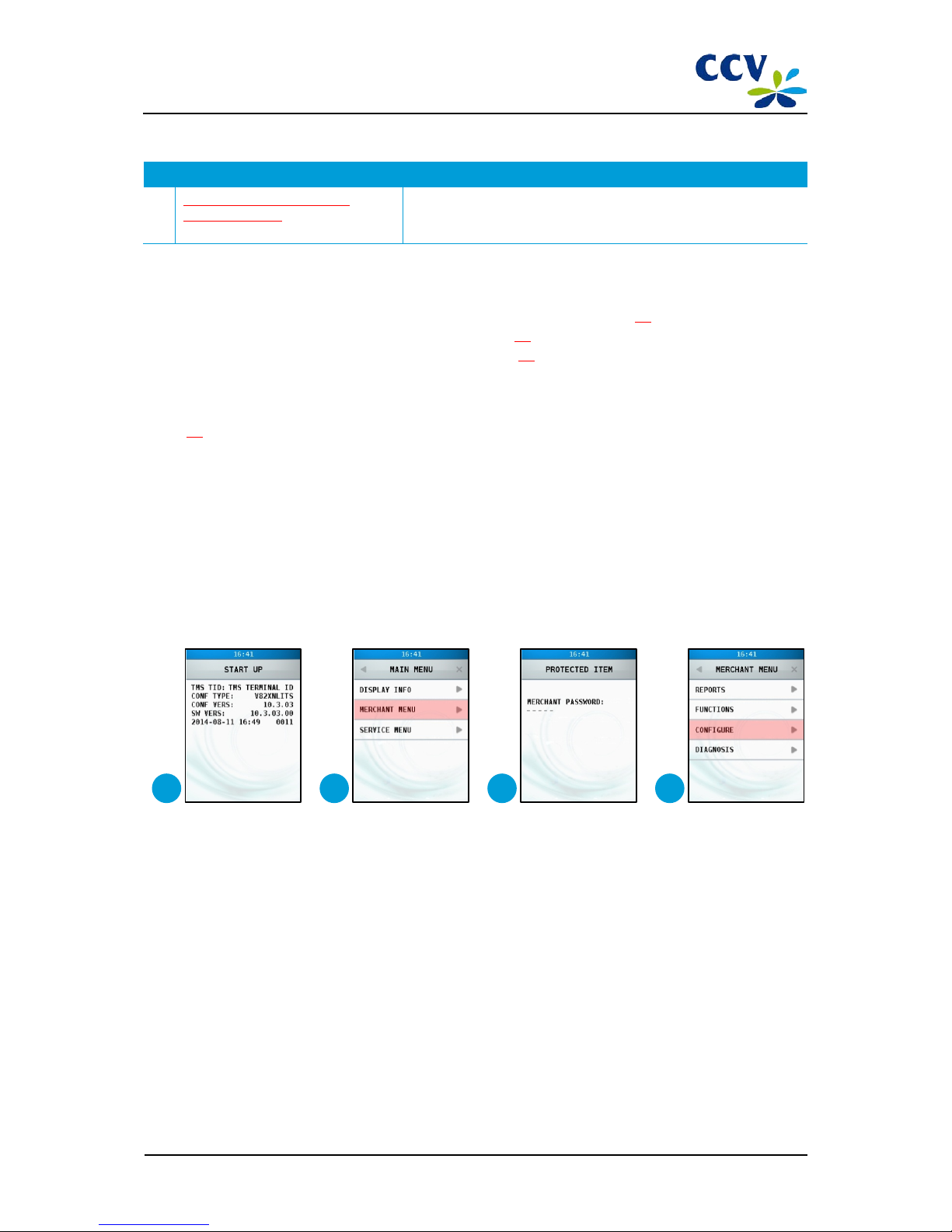
4.3 The merchant menu............................................................................................................................................................ 33
4.3.1 The password of the merchant menu.............................................................................................................. 33
4.3.2 Reports ....................................................................................................................................................................... 33
4.3.3 Functions ................................................................................................................................................................... 36
4.3.4 Configure................................................................................................................................................................... 37
CID087A/15042015 © CCV Services B.V. 3 / 45

VX
820 ITS
Installation
& service manual (version 1.0)
v1.0, Internal
4.4 The service menu ................................................................................................................................................................. 38
4.4.1 The password of the service menu................................................................................................................... 38
4.4.2 Reports ....................................................................................................................................................................... 38
4.4.3 Functions ................................................................................................................................................................... 40
4.4.4 Configure................................................................................................................................................................... 41
4.4.5 Diagnostics................................................................................................................................................................ 43
4.4.6 The PIN pad menu .................................................................................................................................................. 44
5CONTACT INFORMATION.................................................................................................... 45
5.1 Telephone numbers CCV................................................................................................................................................... 45
5.2 Opening hours CCV ............................................................................................................................................................. 45
5.3 General address information CCV................................................................................................................................... 45
CID087A/15042015 © CCV Services B.V. 4 / 45

VX
820 ITS
Installation
& service manual (version 1.0)
v1.0, Internal
1INTRODUCTION
1.1 Objective document
This document describes step by step how a VX 820 ITS PIN pad is to be installed. Next, it describes how to open the
menu of the PIN pad. And finally, it explains all menu options that are relevant for installation and service purposes.
1.2 Target group
This document has been written for CCV or third-party Installation & Service Engineers.
1.3 Status document
This document was last reviewed on 03-10-2013 and is based on software configuration version V82XNLITS 10.3.03 (PIN
pad software version 03.74).
1.4 Typographical conventions
To increase the readability of this document, the typographical conventions listed below are used.
Layout convention Type of information Example
‘Text in-between quotation marks’ Notifications that appear on the
display of the PIN pad or in
AdminLight
Type in <*>, <#> and three times
<OK> as soon as the notification
'START UP' appears on the display.
Bold text Menu options you have to choose or
buttons you have to press in
AdminLight
Choose menu option SUBNET.
<Bold text between brackets> Buttons of the PIN pad you have to
press or menu options you have to
choose on the PIN pad
Type in <*>, <#> and three times
<OK> as soon as the notification
'START UP' appears on the display.
<Text between brackets> Options you have to choose or
buttons you have to press in
Windows
Choose <Start menu>, <Settings>
and subsequently <Control Panel>.
Red text Values you have to enter Enter the password of the merchant
menu (99999) and confirm with
<OK>.
Red and underlined text Hyperlinks and cross references Refer to sub-section 3.2.2 for more
information about the entering of
alphanumerical characters.
CID087A/15042015 © CCV Services B.V. 5 / 45

VX
820 ITS
Installation
& service manual (version 1.0)
v1.0, Internal
1.5 Abbreviations and terms
Abbreviation / Term Meaning
Acquirer Issuer of data for acceptance of PIN and credit-card transactions.
Acquirer parameters Parameters that determine which card types are accepted by the
PIN pad and how the PIN pad deals with these card types.
Admin device port The port (default: 4103) to which the point-of-sale terminal will
send data for AdminLight.
Admin listen port The port (default: 4101) to which the point-of-sale terminal is to
listen for AdminLight commands.
AdminLight Program with which the VX 820 ITS PIN pad can be operated
remotely.
Payment card A card with which payments can be made using a PIN code.
CCV Computercentrum C. van de Velden B.V.
Chip-card reader The card reader that is able to read the chip of a payment card.
Common Terminal Acquirer Protocol (C-TAP) A protocol for a secure way of transaction processing
Configuration parameters Parameters that determine which functions are available on the
PIN pad. Some of these parameters are specific for a certain point
of sale, for example name and address information.
Dynamic Host Configuration Protocol (DHCP) A computer protocol that describes how a computer can obtain
its network settings from a DHCP server.
Gateway A network point indicating which network address may be used
by the PIN pad if the destination is a point outside of the local
network.
IP Internet Protocol
IP address The number with which a point-of-
sale terminal, which is
connected to the Internet or a network, can be identified or
found by other devices on the Internet or the network.
ITS Integrated Terminal Solution
Cash-register system The system used by the cashier for the processing of transactions.
LAN Local Area Network
LAN network Two or more computers that are connected to each other,
directly or via a shared medium.
Local mode The mode in which the PIN pad may be operated on location, by
means of the keys on the PIN pad.
Magnetic card reader The card reader that is able to read the magnetic strip of a
payment card.
New PIN pad A PIN pad that has never been installed and used before at a
customer.
PC Personal Computer
PIN over IP (PoIP) The possibility to carry out transactions by means of an IP
connection certified by the Dutch payment association
Betaalvereniging Nederland.
CID087A/15042015 © CCV Services B.V. 6 / 45

VX
820 ITS
Installation
& service manual (version 1.0)
v1.0, Internal
Abbreviation / Term Meaning
PIN over open Internet The possibility to carry out transactions by means of an IP
connection that is not certified by the Dutch payment
association Betaalvereniging Nederland.
PIN pad The customer part where the card holder enters his PIN code and
accords with the transaction amount.
POS Point Of Sale (Cash register or cashier’s unit).
Privacy shield Shield around the keypad where the PIN code is entered.
POS device port The port (default: 4102) to which the point-of-sale terminal will
send data for the POS system.
POS listen port The port (default: 4100) to which the point-of-sale terminal is to
listen for the POS system commands.
Processor The transaction processer to which transactions are presented
according to the Common Terminal Acquirer Protocol. This party
subsequently passes the transactions on to the correct acquirer.
Remote mode The mode in which the PIN pad may be operated remotely, by
means of AdminLight.
Subnet mask Using the subnet mask, a network administrator is able to
determine which part of an IP address is the network ID, and
which part is the host ID. Thanks to the subnet masks, routers in a
network know at which physical segment a certain address is
located, and whereto the data for that specific address are to be
routed.
Terminal Management System (TMS) System for the management and maintenance of point-of-sale
terminals.
Terminal Management System port Port via which a point-of-sale terminal has access to a TMS
application.
Terminal Management System Terminal ID (TMS
TID)
A unique identification number for a point-of-sale terminal that
serves as a key for access to the TMS.
Used PIN pad A PIN pad that has been installed and used before at a customer.
1.6 Related documents
Document
1 AdminLight – User manual
Version 0.1
October 2013
CCV Services B.V.
CID087A/15042015 © CCV Services B.V. 7 / 45

VX
820 ITS
Installation
& service manual (version 1.0)
v1.0, Internal
2INSTALLING THE PIN PAD
2.1 The difference between a VX 820 ITS PIN pad and a VX 820 PIN pad
The product VX 820 has two versions. Before installing the PIN pad, check which version you have.
•the VX 820 ITS PIN pad that can be linked to a cash-register system
•the VX 820 PIN pad that works in combination with the point-of-sale terminal Vx570
The two versions are not exchangeable!
The VX 820 ITS PIN pad is recognised by the green sticker with the text ITS. This sticker is applied on the
packaging of the product and the bottom of the PIN pad.
2.2 Installation provisions
To install the VX 820 ITS PIN pad, the following provisions must be available at the location of the installation:
•A network connection at 1.5 metres from the PIN pad, at the most, via which the PIN pad can be connected to the
network that also comprises the cash register;
•A wall socket with 220-230V at 1.5 metres from the PIN pad, at the most (preferably a group that does not contain
major users).
To install the PIN pad and provide services on it, you make use of the program AdminLight. The conditions below must
be met in order to use this program:
•AdminLight must have been installed on a PC within the LAN network to which the VX 820 ITS PIN pad and the cash
register are also connected;
•depending on the settings of the LAN network where you are going to install AdminLight, you may need to possess
administrator rights to be able to install the program;
•Java (TM) Platform SE Binary (version 6.0.180 or higher) must have been installed on the PC where you want to use
AdminLight;
•any firewall in the network must have been configured in such a way as to enable communication between
AdminLight and the VX 820 ITS PIN pad. Also, the PIN pad must be able to communicate with the outside world.
2.3 Positioning instructions
The Dutch payment association Betaalvereniging Nederland has a number of objectives, including the security of
electronic payment transactions. To increase this security, Betaalvereniging Nederland has drawn up guidelines for
positioning of the point-of-sale terminal and the use of the card reader.
2.3.1 Positioning the PIN pad
Observe the following instructions when positioning the PIN pad:
•Place the PIN pad in such a way that the card holder is able to screen off the entering of the PIN code with his hand or
body. Therefore, when placing the PIN pad horizontally, the following measurements must be observed:
oplace at a height of minimum 80 cm and maximum 120 cm. This may only be deviated from if the entering of the
PIN code is fully screened off by a special setup.
•The entering of the PIN code may not be visible from an elevation, via mirrors, via cameras, or in any other way.
•The keypad of the PIN pad must be set up in such a way that the card holder has sufficient privacy while entering the
PIN code during the transaction. This makes it impossible (within reason) for third parties to view the PIN code.
•The PIN pad is provided with a privacy shield. This shield around the keypad can be used by the card holder to screen
off the entering of the PIN code. If your PIN pad does not have a privacy shield, please contact our Product Support
Desk via +31 (0)88 228 9783.
CID087A/15042015 © CCV Services B.V. 8 / 45

VX
820 ITS
Installation
& service manual (version 1.0)
v1.0, Internal
2.3.2 Using the card reader
Make sure the card remains visible to the card holder. It is best to allow the card holder to put his payment card into the
chip-card reader or slide it through the magnetic card reader himself. When this is not possible for practical reasons, then
make sure you show the card holder how you put the payment card into the chip-card reader or slide it through the
magnetic card reader.
2.3.3 Environmental factors
Environmental factors may affect the operation of the equipment. Keep this in mind when positioning the equipment.
Your point-of-sale terminal is able to operate under the following environmental factors:
•an ambient temperature of between 0°C and 50°C
•a relative humidity of between 5% and 90%
Avoid:
•shocks and vibrations
•direct sunlight or heat-emitting objects
•excessive heat and dust
•oil and dirt
•water or condensation
•Placing of the terminal close to objects that cause excessive current fluctuations and/or electromagnetic fields
2.4 Information required to be able to carry out an installation
To be able to install the VX 820 ITS PIN pad, you need to have the following information at your disposal:
•IP address, subnet mask and gateway for the PIN pad. This information should be available at the customer’s or from
the supplier of the cash register;
•TMS TID of the PIN pad;
•TMS IP address and the TMS port for the PIN pad.
2.5 Overview of the installation, step by step
Step Explanation
1 Preparing for installation Before installation, check the following:
•whether all necessary facilities are available on the location of
installation
•whether all positioning instructions have been met
•whether you have all necessary information at hand
2 Installing AdminLight Install AdminLight.You need this program to install the VX 820 ITS.
3 Configuring the communication
settings of the PIN pad
To be able to install the VX 820 ITS PIN pad, the PIN pad must be able
to communicate with AdminLight. First, configure the communication
settings of the VX 820 ITS. Next, connect the PIN pad to AdminLight.
4 Connecting the PIN pad to
AdminLight
5 Installing the PIN pad with AdminLight
(new PIN pad)
Open the menu of the VX 820 ITS PIN pad using AdminLight. Next,
carry out the actions necessary to install the PIN pad.
Installing the PIN pad with AdminLight
(used PIN pad)
6 Activating the PIN pad A used PIN pad must be activated with AdminLight after installation.
You do not need to carry out this step if the PIN pad is new and never
used at a customer.
7 Configuring OPI settings (conditional) You can configure the OPI settings if you want to have the OPI
communication run via RS232 rather than via the Ethernet.
CID087A/15042015 © CCV Services B.V. 9 / 45

VX
820 ITS
Installation
& service manual (version 1.0)
v1.0, Internal
Step Explanation
8 Checking whether the PIN pad
operates correctly
After installation of the PIN pad, check whether the PIN pad operates
correctly. To do this, you carry out a day opening (if necessary!) and a
test transaction.
2.6 Step 1: preparing for installation
Before installation, check the following:
•whether all necessary facilities are available on the location of installation (see section 2.2);
•whether all positioning instructions have been met (see section 2.3);
•whether you have all necessary information at hand (see section 2.4).
2.7 Step 2: installing AdminLight
Install AdminLight.For more information about installing AdminLight, please refer to the AdminLight user manual (see
section 1.6).
2.8 Step 3: configuring the communication settings of the PIN pad
First, configure the communication settings for the VX 820 ITS PIN pad. In order to carry out this step, you need the
following information. This information should be available from the supplier of the cash register or at the customer’s!
•Terminal IP address
•Subnet mask
•Gateway
Connect the VX 820 ITS PIN pad to the LAN network and a power supply connected to a wall socket with 220-230V. Then
carry out the following actions to configure the communication settings of the PIN pad:
1 Type in <*>, <#> and three times <OK> as soon as the notification 'START UP' appears on the display. Wait until
the menu structure appears on the display and continue on to action 3. It may take a little while before the menu
structure appears on the display!
2 Choose the menu option <MERCHANT MENU>.
3 Enter the password of the merchant menu (99999) and confirm with <OK>.
4 Choose the menu option <CONFIGURE>.
1
2
3
4
CID087A/15042015 © CCV Services B.V. 10 / 45

VX
820 ITS
Installation
& service manual (version 1.0)
v1.0, Internal
5 Choose the menu option <TERMINAL>.
6 Choose the menu option <COMMUNICATION>.
7 Choose the menu option <TCP/IP>.
8 Choose the menu option <IP MODE>.
9 Choose the menu option <STATIC IP ADDRESSES>.
10 Choose the menu option <IP ADDRESSES.
11 Choose the menu option <TERMINAL IP ADDRESS>.
12 Press <CORR>.
13 Enter the IP address and confirm with <OK>. To enter the IP address,, you must enter multiple full stops (.). Enter
this punctuation mark by entering <1> several times. Refer to sub-section 3.3.1 for more information about the
entering of alphanumerical characters.
14 Choose menu option <SUBNET MASK>.
15 Press <CORR>.
16 Enter the subnet mask and confirm with <OK>. To enter the subnet mask, you must enter multiple full stops
(.).Enter this punctuation mark by entering <1> several times. Refer to sub-section 3.3.1 for more information
about the entering of alphanumerical characters.
5
6
7
8
9
10
11
12
13
14
15
16
CID087A/15042015 © CCV Services B.V. 11 / 45

VX
820 ITS
Installation
& service manual (version 1.0)
v1.0, Internal
17 Choose menu option <GATEWAY>.
18 Press <CORR>.
19 Enter the gateway and confirm with <OK>. To enter the gateway, you must enter multiple full stops (.).Enter this
punctuation mark by entering <1> several times. Refer to sub-section 3.3.1 for more information about the
entering of alphanumerical characters.
20 Choose .
21 Wait until the communication settings have been configured.
22 The communication settings of the PIN pad have now been configured.
2.9 Step 4: connecting the PIN pad to AdminLight
Add the PIN pad in AdminLight. For more information about adding PIN pads to AdminLight, please refer to the
AdminLight user manual (see section 1.6).
2.10 Step 5: installing the PIN pad with AdminLight
The installation process differs for a new PIN pad and a PIN pad that has allready been installed and used at a customer.
Follow the instructions in sub-section 2.10.1 (new PIN pad) or 2.10.2 (used PIN pad) to install the PIN pad.
17
18
19
20
21
22
CID087A/15042015 © CCV Services B.V. 12 / 45

VX
820 ITS
Installation
& service manual (version 1.0)
v1.0, Internal
2.10.1 New PIN pad
Carry out the actions below to install the PIN pad:
Action Explanation
1 Select the desired PIN pad in the drop-
down menu and choose Start menu.
2 The main menu of the VX 820 ITS PIN pad
will now be opened.
Choose menu option SERVICE MENU.
3 A pop-up will be opened in which you
must enter the password for the service
menu.
Enter the password and choose OK.
Contact our Product Support Desk if you are not familiar with the
calculation of the password for the SERVICE MENU.
4 The service menu is now opened.
Choose menu option FUNCTIONS.
CID087A/15042015 © CCV Services B.V. 13 / 45

VX
820 ITS
Installation
& service manual (version 1.0)
v1.0, Internal
Action Explanation
5 Choose menu option TERMINAL.
6 Choose menu option HW INSTALLATION.
7 Choose menu option TERMINAL
INSTALL.
8 A pop-up will be opened in which you
must enter the TMS TID.
Enter the TMS TID and confirm with OK.
9 A pop-up will be opened in which you
must enter the TMS TID once again.
Enter the TMS TID once again and confirm
with OK.
CID087A/15042015 © CCV Services B.V. 14 / 45

VX
820 ITS
Installation
& service manual (version 1.0)
v1.0, Internal
Action Explanation
10 A pop-up will be opened in which you
must enter the TMS IP address of the PIN
pad.
The default IP address is given between
brackets. Choose OK,
or enter an
alternative TMS IP address before
choosing OK.
Contact our Product Support Desk if you want to use an alternative
IP address. Our employees will help you implement the TMS IP
address in the TMS for you. You may enter the following TMS IP
addresses:
•Public Internet: 193.173.53.101
•PoIP: 194.104.96.44
11 A pop-up will be opened in which you
must enter the TMS port for the PIN pad.
The default TMS port is given between
brackets.
Choose OK, or enter an alternative TMS
port before choosing OK.
The installation of the VX 820 ITS PIN pad
will now be started.
12 During the installation process, check the
name and address information of the
point of sale where you are installing the
PIN pad.
13 Choose OK if the name and address
information of the point of sale are
correct.
Choose STOP if the name and address
information of the point of sale are not
correct. Next, contact our Product Support
Desk for the validation of the name and
address information.
CID087A/15042015 © CCV Services B.V. 15 / 45

VX
820 ITS
Installation
& service manual (version 1.0)
v1.0, Internal
Action Explanation
14 Wait until the installation process is
completed.
When the installation has been completed
successfully, the following notification will
appear in AdminLight: 'INSTALLATION
SUCCESSFUL'. The session with
AdminLight will end automatically.
15 Wait until the PIN pad is activated.
The activation process is not visible in
AdminLight. When the activation has
been completed successfully, the
following notification will appear on the
display of the PIN pad: 'WELCOME YOUR
CARD PLEASE'.
16 Proceed to step 7 (Configuring OPI
settings) or step 8 (Checking whether the
PIN pad operates correctly).
You carry out step 7 only if you want the OPI communication run
via RS232 rather than via the Ethernet.
CID087A/15042015 © CCV Services B.V. 16 / 45

VX
820 ITS
Installation
& service manual (version 1.0)
v1.0, Internal
2.10.2 Used PIN pad
Carry out the actions below to install the PIN pad:
Action Explanation
1 Select the desired PIN pad in the drop-
down menu and choose Start menu.
2 The main menu of the VX 820 ITS PIN pad
will now be opened.
Choose menu option SERVICE MENU.
3 A pop-up will be opened in which you
must enter the password for the service
menu.
Enter the password and choose OK.
Contact our Product Support Desk if you are not familiar with the
calculation of the password for the SERVICE MENU.
4 The service menu is now opened.
Choose menu option FUNCTIONS.
CID087A/15042015 © CCV Services B.V. 17 / 45

VX
820 ITS
Installation
& service manual (version 1.0)
v1.0, Internal
Action Explanation
5 Choose menu option TERMINAL.
6 Choose menu option HW INSTALLATION.
7 Choose menu option TERMINAL
INSTALL.
8 A pop-up will be opened in which you
must enter the TMS TID.
Enter the TMS TID and confirm with OK.
9 A pop-up will be opened in which you
must enter the TMS TID once again.
Enter the TMS TID once again and confirm
with OK.
CID087A/15042015 © CCV Services B.V. 18 / 45

VX
820 ITS
Installation
& service manual (version 1.0)
v1.0, Internal
Action Explanation
10 A pop-up will be opened in which you
must enter the TMS IP address of the PIN
pad.
The default IP address is given between
brackets. Choose OK,
or enter an
alternative TMS IP address before
choosing OK.
Contact our Product Support Desk if you want to use an alternative
IP address. Our employees will help you implement the TMS IP
address in the TMS for you. You may enter the following TMS IP
addresses:
•Public Internet: 193.173.53.101
•PoIP: 194.104.96.44
11 A pop-up will be opened in which you
must enter the TMS port for the PIN pad.
The default TMS port is given between
brackets.
Choose OK, or enter an alternative TMS
port before choosing OK.
The installation of the VX 820 ITS PIN pad
will now be started.
12 During the installation process, check the
name and address information of the
point of sale where you are installing the
PIN pad.
13 Choose OK if the name and address
information of the point of sale are
correct.
Choose STOP if the name and address
information of the point of sale are not
correct. Next, contact our Product Support
Desk for the validation of the name and
address information.
CID087A/15042015 © CCV Services B.V. 19 / 45

VX
820 ITS
Installation
& service manual (version 1.0)
v1.0, Internal
Action Explanation
14 Wait until the installation process is
completed.
When the installation has been completed
successfully, the following notification will
appear in AdminLight: 'INSTALLATION
SUCCESSFUL'. Next, a configuration
session is started.
15 Wait until the configuration session is
completed.
When the configuration session has been
completed successfully, the following
notification will appear in AdminLight:
'CONFIGURATION FINISHED'. Next, keys
may be uploaded to the PIN pad.
16 Wait until the keys are uploaded.
When the keys are uploaded, the
following notification will appear in
AdminLight: 'LOADING KEYS FINISHED'.
Next, an acquirer parameter session is
started.
CID087A/15042015 © CCV Services B.V. 20 / 45
Table of contents
Other CCV Payment Terminal manuals
Popular Payment Terminal manuals by other brands

CHASE Paymentech
CHASE Paymentech VeriFone Vx Series Quick reference guide

First Data
First Data FD400 Quick setup guide

Tech Logic
Tech Logic Desk3200 Quick reference guide

Ingenico group
Ingenico group Move/3500 quick start guide

PAX
PAX A920 Quick reference guide

dejavoo
dejavoo Z Series Quick reference guide