manuals.online logo
Brands
  1. Home
  2. •
  3. Brands
  4. •
  5. Ecco
  6. •
  7. Security System
  8. •
  9. Ecco 6500 Series User manual

Ecco 6500 Series User manual

Do not install and/or operate this safety product unless you have read and understand the
safety information contained in this manual.
1. Proper installation combined with operator training in the use, care, and maintenance of emergency warning devices
are essential to ensure the safety of you and those you are seeking to protect.
2. Exercise caution when working with live electrical connections.
3. This product must be properly grounded. Inadequate grounding and/or shorting of electrical connections can cause
high current arcing, which can cause personal injury and/or severe vehicle damage, including re.
4. Proper placement and installation are vital to the performance of this warning device. Install this product so that output
performance of the system is maximized and the controls are placed within convenient reach of the operator so that
s/he can operate the system without losing eye contact with the roadway.
5. It is the responsibility of the vehicle operator to ensure during use that all features of this product work correctly. In
use, the vehicle operator should ensure the projection of the warning signal is not blocked by vehicle components
(i.e., open trunks or compartment doors), people, vehicles, or other obstructions.
6. The use of this or any other warning device does not ensure all drivers can or will observe or react to a warning signal.
Never take the right-of-way for granted. It is your responsibility to be sure you can proceed safely before entering an
intersection, driving against trafc, responding at a high rate of speed, or walking on or around trafc lanes.
7. This equipment is intended for use by authorized personnel only. The user is responsible for understanding and
obeying all laws regarding warning signal devices. Therefore, the user should check all applicable city, state, and
federal laws and regulations. The manufacturer assumes no liability for any loss resulting from the use of this
warning device.
WARNING!
Failure to install or use this product according to manufacturers recommendations may result in property
damage, serious bodily/personal injury, and/or death to you and those you are seeking to protect!
Specications:
Size: 6550X - Permanent 6.8” dia. x 4.9” high
6550X-VM - V/Magnet 7.8” dia. x 5.6” high
6570X - Permanent 6.8” dia. x 6.7” high
6570X-VM - V/Magnet 7.8” dia. x 7.5” high
Weight: 6550X - Permanent approx. 1.2 lbs.
6550X-VM - V/Magnet approx. 2.7 lbs.
6570X - Permanent approx. 1.4 lbs.
6570X-VM - V/Magnet approx. 2.8 lbs.
!
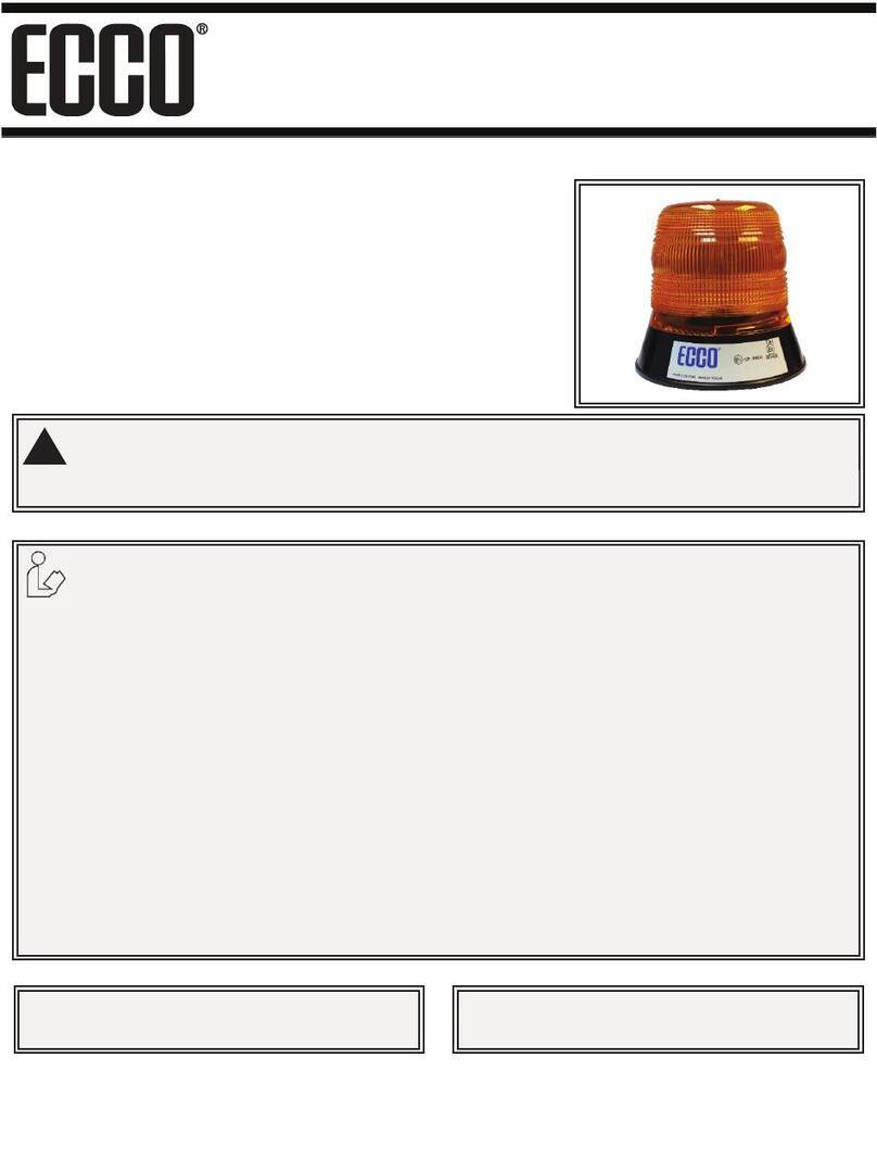
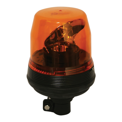
Models 6550 & 6570 Strobe Beacons
6500 Series strobe beacons are designed to meet SAE
J1318 Class II specications. Available in 5” & 7” height
proles, the 6500 Series feature a thread-on lens,
snap-t ashtube, and 3 bolt ange/1” pipe or magnetic
mounting options. 6500 Series strobes will function
on 12-48 VDC electrical systems and offer a choice of
80FPM double ash or 65FPM quad ash operation.
Installation and Operation Instructions
360° Strobe Beacon
Input Voltage: 12 to 48 VDC (9-56V)
Current Draw: 2.37 Amps - Peak
30.3 Watts - Maximum
Operating temperature range: -30 to +50ºC
920-6500-00 Rev. D Page 1 of 3
Installation & Mounting:
Permanent Mounting: Select the desired location on a at surface for the
strobe beacon to be mounted. The visibility of the strobe ash and ease
of wiring access should be taken into consideration in the selection of the
mounting location. Using the base gasket as a template, mark the three
mounting hole locations (see Figure 1). Drill the holes using the correct
drill size to match the selected hardware. A fourth hole may be drilled for
wire access as shown in Figure 1, or the wires may be routed through the
slot in the base for external access. Connect the power wires as shown in
the wiring section (see Figure 3).
Caution: When drilling into any vehicle surface, make
sure the area is free from any electrical wires, fuel lines,
vehicle upholstery, etc. that could be damaged
Important! This unit is a safety device, and it must be
connected to its own separate, fused power point to assure
its continued operation should any other electrical
accessory fail.
Pipe Mounting: The 6500 series base comes with 1” NPT threads for pipe
mounting.
Wiring Instructions:
The wiring for the strobe is as shown in Figure 3 below. All wiring should be
a minimum of 18AWG. The positive line must have a 10 amp fuse. A switch
may be used to control the on/off function. Note: Power must be shut off
when changing ash modes.
Temporary Mounting, Vacuum-Magnet Mount: The Vacuum-Magnet
Mount feature includes a suction cup on the bottom of the beacon, with
a magnet inside of the suction cup, for a secure, temporary mount. The
beacon should be placed in the center of the roof where the least amount
of curvature occurs. Before installing, make sure the mounting surface is
clean and there is no debris on the bottom of the beacon or on the roof of
the vehicle, which could reduce the holding power of the suction cup and
magnet. Place and remove the beacon without sliding to avoid scratching
the paint on the vehicle. After placement, the beacon should adhere rmly
to the surface. If the unit slides or moves easily, a proper installation has
not been obtained. To release the vacuum, lift the tab to release the airlock
(see Figure 2). To protect the Vacuum-Magnet Mount assembly, return
beacon to the box when not in use. Do not attempt to attach the beacon
to an ice-covered surface.
EXTERIOR MOUNTING
HOLE LOCATION
IF DESIRED DRILL
HOLE IN CENTER FOR
WIRE ACCESS
UNDERNEATH BEACON
BASE GASKET
MOUNTING
SURFACE
INTERIOR MOUNTING
HOLE LOCATION
Figure 1
FUSE (10 AMP)
(USER SUPPLIED)
GROUND
GROUND
SWITCH
(USER SUPPLIED)
WHITE
N/C = DOUBLE FLASH
GROUNDED = QUAD FLASH
RED
BLACK
Maintenance & Troubleshooting:
Most strobe failures can be traced to wiring or battery problems. Check all
wiring and connections to insure the correct voltage is reaching the strobe
light. If the strobe operates erratically or stops completely, and the wiring
is not at fault, the ashtube is probably worn. To replace it, remove the
lens, and remove the ashtube by squeezing on the tabs on the side of the
tube holder and pulling off. WARNING! The strobe power supply is a high
voltage device. Wait 5 minutes after turning off power before removing lens
for access to internal parts. Plug in the new tube assembly. See Figure 4.
Note: The connector is keyed to ensure proper orientation. Do not force. If
trouble continues, return product to your local dealer for warranty replace-
ment, or call ECCO Customer Service for assistance (800) 635-5900.
Figure 3
Figure 4
920-6500-00 Rev. D Page 2 of 3
PULL/ROLL TAB
UPWARD TO RELEASE
VACUUM
Figure 2
WARNING!
Maximum recommended vehicle speed for safe operation
using the Vacuum Mount model is 65 mph (104 km/h), when tted
to the center of a vehicle roof of steel construction. Higher speeds
could cause the mount to fail, resulting in the beacon ying off of the
vehicle, which could cause damage to other vehicles, and injury or
death to the passengers. The vacuum-magnet mount is not intended
as a permanent mounting for the beacon. The vacuum-magnet
mount unit must be mounted on a at smooth magnetic surface (i.e.
no berglass, ribbed style roofs, etc.). Ensure that the magnet is
kept clean.
!
Description Part Number
Flash Tube R6501FT
Lens, 4” (replacement for 6550) R6050LX*
Lens, 6” (replacement for 6570) R6070LX*
Magnet Mount Kit A6600MK
Self Leveling Bracket A6600SLB
Branch Guard (for use with 6550) A6050BG
Branch Guard (for use with 6570) A6070BG
Dust Cover (for use with 6550) A6050DC
Dust Cover (for use with 6570) A6070DC
Vibration Dampening Kit A6600VDK
Black Top A6600BT
Replacement Parts & Accessories:
Manufacturer Limited Warranty and Limitation of Liability:
Manufacturer warrants that on the date of purchase this product will conform to Manufacturer’s specications for this product (which are available from the
Manufacturer upon request), and Manufacturer further warrants that this product is free from defects in materials and workmanship. This Limited Warranty
extends for two (2) years from the date of purchase. Other warranties may apply, call Manufacturer for details. Manufacturer will, at its discretion, repair or
replace any product found by the Manufacturer to be defective and subject to this Limited Warranty.
DAMAGE TO PARTS OR PRODUCTS RESULTING FROM TAMPERING, ACCIDENT, ABUSE, MISUSE, NEGLIGENCE, UNAPPROVED MODIFICATIONS, FIRE OR
OTHER HAZARD; IMPROPER INSTALLATION OR OPERATION; OR NOT BEING MAINTAINED IN ACCORDANCE WITH THE MAINTENANCE PROCEDURES
SET FORTH IN MANUFACTURER’S INSTALLATION AND OPERATING INSTRUCTIONS VOIDS THIS LIMITED WARRANTY.
ORAL STATEMENTS OR REPRESENTATIONS ABOUT THE PRODUCT WHICH MAY HAVE BEEN MADE BY SALES-PEOPLE, DEALERS, AGENTS OR OTHER
MANUFACTURER’S REPRESENTATIVES DO NOT CONSTITUTE WARRANTIES. THIS LIMITED WARRANTY MAY NOT BE AMENDED, MODIFIED, OR EN-
LARGED EXCEPT BY A WRITTEN AGREEMENT SIGNED BY AN AUTHORIZED OFFICIAL OF MANUFACTURER WHICH EXPRESSLY REFERS TO THIS LIM-
ITED WARRANTY.
Exclusion of Other Warranties:
MANUFACTURER MAKES NO OTHER WARRANTIES, EXPRESS OR IMPLIED. THE IMPLIED WARRANTIES FOR MERCHANTABILITY OR FITNESS FOR A
PARTICULAR PURPOSE ARE HEREBY EXCLUDED AND SHALL NOT APPLY TO THE PRODUCT. BUYER’S SOLE AND EXCLUSIVE REMEDY IN CONTRACT,
TORT, OR UNDER ANY OTHER THEORY AGAINST MANUFACTURER REGARDING THE PRODUCT AND ITS USE SHALL BE THE REPLACEMENT OR REPAIR
OF THE PRODUCT AS DESCRIBED ABOVE.
Limitation of Liability:
IN THE EVENT OF LIABILITY FOR DAMAGES ARISING OUT OF THIS LIMITED WARRANTY OR ANY OTHER CLAIM RELATED TO THE MANUFACTURER’S
PRODUCTS, MANUFACTURER’S LIABILITY FOR DAMAGES SHALL BE LIMITED TO THE AMOUNT PAID FOR THE PRODUCT AT THE TIME OF THE ORIGI-
NAL PURCHASE. IN NO EVENT SHALL MANUFACTURER BE LIABLE FOR LOST PROFITS, THE COST OF SUBSTITUTE EQUIPMENT OR LABOR, PROP-
ERTY DAMAGE, OR OTHER SPECIAL, CONSEQUENTIAL, OR INCIDENTAL DAMAGES BASED UPON ANY CLAIM FOR BREACH OF CONTRACT, IMPROPER
INSTALLATION, NEGLIGENCE, OR OTHER CLAIM, EVEN IF MANUFACTURER OR A MANUFACTURER’S REPRESENTATIVE HAS BEEN ADVISED OF THE
POSSIBILITY OF SUCH DAMAGES. MANUFACTURER SHALL HAVE NO FURTHER OBLIGATION OR LIABILITY WITH RESPECT TO THE PRODUCT OR ITS
SALE, OPERATION AND USE, AND MANUFACTURER NEITHER ASSUMES NOR AUTHORIZES THE ASSUMPTION OF ANY OTHER OBLIGATION OR LIABILITY
IN CONNECTION WITH SUCH PRODUCT.
This Limited Warranty denes specic legal rights. You may have other legal rights which vary from state to state. Some states do not allow the exclusion or
limitation of incidental or consequential damages.
833 West Diamond St
Boise, Idaho 83705
Customer Service
USA 800-635-5900
UK +44 (0)113 237 5340
AUS +61 (0)3 63322444
www.eccogroup.com
920-6500-00 Rev. D Page 3 of 3
©2010
NOTE: Operating the vehicle without the outer lens installed on the product may result in damage that will NOT be
covered under warranty.
!
*where (X) indicates color: A = Amber, B = Blue, C = Clear, G = Green, R = Red

This manual suits for next models

2

Other Ecco Security System manuals

Ecco 7965 Series User manual

Ecco

Ecco 7965 Series User manual

Ecco 7945 User manual

Ecco

Ecco 7945 User manual

Ecco EB7260 Series User manual

Ecco

Ecco EB7260 Series User manual

Ecco EB7930 Series User manual

Ecco

Ecco EB7930 Series User manual

Ecco EB7180 Series User manual

Ecco

Ecco EB7180 Series User manual

Ecco EB7800 Series User manual

Ecco

Ecco EB7800 Series User manual

Ecco B200 R65 Manual

Ecco

Ecco B200 R65 Manual

Ecco 6260 Series User manual

Ecco

Ecco 6260 Series User manual

Ecco EB8160 User manual

Ecco

Ecco EB8160 User manual

Ecco 6550 Owner's manual

Ecco

Ecco 6550 Owner's manual

Ecco 400 Series Owner's manual

Ecco

Ecco 400 Series Owner's manual

Ecco 7965 Series User manual

Ecco

Ecco 7965 Series User manual

Ecco EB7260 Series Owner's manual

Ecco

Ecco EB7260 Series Owner's manual

Ecco K7000B User manual

Ecco

Ecco K7000B User manual

Ecco Pulse II 7945 Series User manual

Ecco

Ecco Pulse II 7945 Series User manual

Ecco EB5200 Owner's manual

Ecco

Ecco EB5200 Owner's manual

Popular Security System manuals by other brands

CellGate WATCHMAN EVO WP450 Series Quick install guide

CellGate

CellGate WATCHMAN EVO WP450 Series Quick install guide

Pneumercator LC1000 SERIES instruction manual

Pneumercator

Pneumercator LC1000 SERIES instruction manual

Mobi Technologies 1 Ch HD Operation manual

Mobi Technologies

Mobi Technologies 1 Ch HD Operation manual

SJE Rhombus Xpert Alert Operation guide

SJE Rhombus

SJE Rhombus Xpert Alert Operation guide

dallmeier VMC-1 quick start guide

dallmeier

dallmeier VMC-1 quick start guide

FBII XL Star 4500 owner's manual

FBII

FBII XL Star 4500 owner's manual

Night Owl PRO Series 8CH instruction manual

Night Owl

Night Owl PRO Series 8CH instruction manual

switel HSIP 6000 user manual

switel

switel HSIP 6000 user manual

Luda Farm machineCam quick guide

Luda Farm

Luda Farm machineCam quick guide

National Security Systems Security System user guide

National Security Systems

National Security Systems Security System user guide

Hochiki VoiceNET Training manual

Hochiki

Hochiki VoiceNET Training manual

AVT 5466 manual

AVT

AVT 5466 manual

Texecom Premier 412 user guide

Texecom

Texecom Premier 412 user guide

Ontech Alarmbox 9012 user manual

Ontech

Ontech Alarmbox 9012 user manual

Pfannenberg BE BG10D-P Series instruction manual

Pfannenberg

Pfannenberg BE BG10D-P Series instruction manual

Omron F150-3 - datasheet

Omron

Omron F150-3 - datasheet

GeoVision GV-Mini user manual

GeoVision

GeoVision GV-Mini user manual

XODO SA1 user manual

XODO

XODO SA1 user manual

manuals.online logo
manuals.online logoBrands
  • About & Mission
  • Contact us
  • Privacy Policy
  • Terms and Conditions

Copyright 2025 Manuals.Online. All Rights Reserved.