manuals.online logo
Brands
  1. Home
  2. •
  3. Brands
  4. •
  5. Ecco
  6. •
  7. Security System
  8. •
  9. Ecco Pulse II 7945 Series User manual

Ecco Pulse II 7945 Series User manual

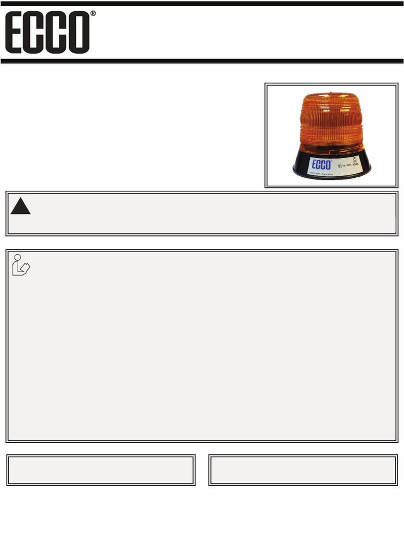
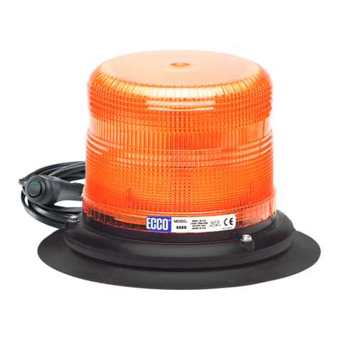
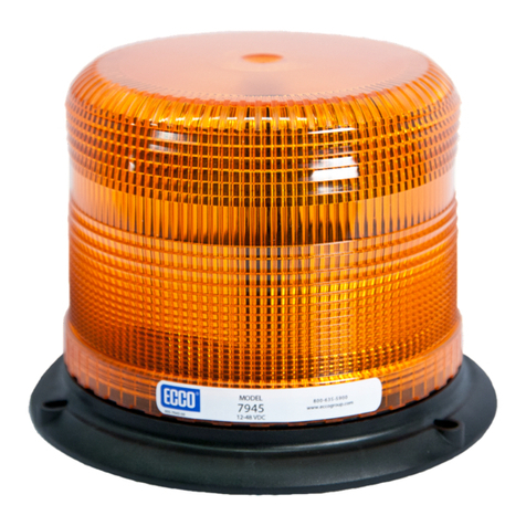
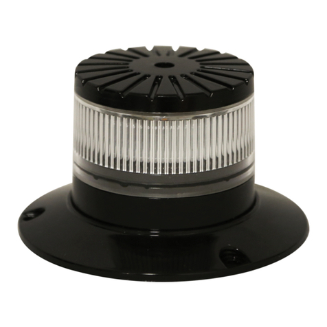
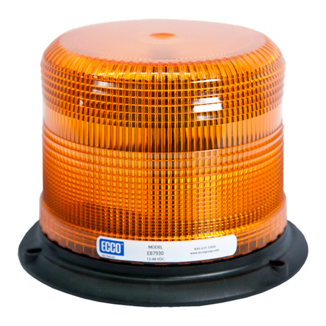
ECCO’s 7945 & 7950 series LED beacons are designed to
meetSAEJ845ClassIIspecications(AmberandClear
only). The 7945 & 7950 features 12-48 VDC operation, 3
boltmountingange,integrated1”pipemount,&optional
vacuum-magnet mount.
920-0220-00 Rev. D Page 1 of 4
Do not install and/or operate this safety product unless you have read and understand the
safety information contained in this manual.
1. Proper installation combined with operator training in the use, care, and maintenance of emergency warning devices
are essential to ensure the safety of you and those you are trying to protect.
2. Exercise caution when working with live electrical connections.
3. This product must be properly grounded. Inadequate grounding and/or shorting of electrical connections can cause
highcurrentarcing,whichcancausepersonalinjuryand/orseverevehicledamage,includingre.
4. Proper placement and installation are vital to the performance of this warning device. Install this product so that out-
put performance of the system is maximized and the controls are placed within convenient reach of the operator so
that s/he can operate the system without losing eye contact with the roadway.
5. It is the responsibility of the vehicle operator to ensure during use that all features of this product work correctly. In
use, the vehicle operator should ensure the projection of the warning signal is not blocked by vehicle components
(i.e.,opentrunksorcompartmentdoors),people,vehicles,orotherobstructions.
6. The use of this or any other warning device does not ensure all drivers can or will observe or react to a warning sig-
nal. Never take the right-of-way for granted. It is your responsibility to be sure you can proceed safely before enter-
inganintersection,drivingagainsttrafc,respondingatahighrateofspeed,walkingonoraroundtrafclanes.
7. This equipment is intended for use by authorized personnel only. The user is responsible for understanding and
obeying all laws regarding warning signal devices. Therefore, the user should check all applicable city, state, and fed-
eral laws and regulations. The manufacturer assumes no liability for any loss resulting from the use of this warning
device.
WARNING!
Failure to install or use this product according to manufacturers recommendations may result in property dam-
age, serious bodily/personal injury, and/or death to you and those you are seeking to protect!
!
IMPORTANT! Read all instructions before installing and using. Installer: This manual must be
delivered to the end user.
Installation and Operation Instructions
360° LED Beacon
Caution: When drilling into any vehicle surface,
make sure that the area is free from any electrical wires,
fuel lines, vehicle upholstery, etc. that could be damaged.
Specications:
Size:  7945:6.0”dia.x4.8”high
  7950:6.0”dia.x6.8”high
Weight: approx. 3 lbs.
Input Voltage: 12-48 VDC system
Input Current: 0.5A @ 12.8 VDC
Maximum power consumption: 6.4 Watts
Temp. Range: -30°C to +50°C
Carefullyremovethebeaconandplaceitonaatsurface.Examine
the unit for transit damage, and locate all parts. If damage is found,
or parts are missing, contact the transit company or ECCO. Do not
use damaged or broken parts.
Permanent Mounting:
SelectthedesiredlocationonaatsurfacefortheLEDbeaconto
bemounted.Thevisibilityoftheashandeaseofwiringaccess
should be taken into consideration in the selection of the mounting
location.
1. Using the base gasket as a template, mark the three mount-
ingholelocations(seeFigure1).
2. Drilltheholesusinga7/32”drillsize.
3. AfourthholemaybedrilledforwireaccessasshowninFig-
ure 1, or the wires may be routed through the slot in the base
for external access.
4. Connectthepowerwiresasshowninthewiringsection(see
Figure3).
5. Mount the beacon with #8 hardware.
Pipe Mounting:
The7945&7950seriesbasecomeswith1”NPTthreadsforpipe
mounting.
Figure 1
Temporary Mounting, Vacuum-Magnet Mount:
The 7945 & 7950 series beacons are available as vacuum-magnet
mount(7945X-VM&7950X-VM)units.TheVacuum-MagnetMount
feature includes a suction cup on the bottom of the beacon, with a
magnet inside of the suction cup, for a secure, temporary mount. The
beacon should be placed in the center of the roof where the least
amount of curvature occurs. Before installing, make sure there is
no debris on the bottom of the beacon or on the roof of the vehicle,
which could reduce the holding power of the suction cup and mag-
net. Place and remove the beacon without sliding to avoid scratching
the paint on the vehicle. After placement, the beacon should adhere
rmlytothesurface.Iftheunitslidesormoveseasily,aproperin-
stallation has not been obtained. To release the vacuum, lift the tab
toreleasetheairlock(seeFigure2).ToprotecttheVacuum-Magnet
Mount assembly, return beacon to the box when not in use. Do not
attempt to attach the beacon to an ice-covered surface.
920-0220-00 Rev. D Page 2 of 4
Important! This unit is a safety device, and it must be
connected to its own seperate, fused power point to as-
sure its continued operation should any other electrical
accessory fail.
!
WARNING!
Maximum recommended vehicle speed for safe operation
using the Vacuum Mount model is 65 mph (104 km/h), when tted
to the center of a vehicle roof of steel construction. Higher speeds
could cause the mount to fail, resulting in the beacon ying off
of the vehicle, which could cause damage to other vehicles, and
injury or death to the passengers. The vacuum-magnet mount is not
intended as a permanent mounting for the beacon. The vacuum-
magnet mount unit must be mounted on a at smooth magnetic
surface (i.e. no berglass, ribbed style roofs, etc.). Insure that the
magnet is kept clean.
!
Figure 2
Installation & Mounting:
WARNING!
Failure to follow these instructions can result in  re or injury from excessive heat build up.
Operatorisresponsibleforensuringcigaretteadaptertscorrectlyintocigarette/auxillaryoutletused.
Forproperoperation,verifycigarette/auxillaryoutletcircuitisratedtosupply,aminimumof10amps.(Seespecications
section for rated current in amperes).
Do not exceed the current rating for the cigarette lighter power outlet recommended by vehicle manufacturer.
Keep cigarette lighter adapter, and outlet, clean and free of debris.
Do not use the cigarette lighter adapter when wet.
Insert cigarette lighter adapter fully into the outlet for proper connection.
Grasp cigarette lighter adapter, NOT cord, to remove from outlet.
Remove cigarette lighter adapter completely from outlet when light is not in use.
Wiring Instructions:
Important: Disable power before wiring the beacon.
920-0220-00 Rev.D Page 3 of 4
Notes:
1.Largerwiresandtightconnectionswillprovidelongerservicelifeforcomponents.Forhighcurrentwiresitishighly
recommended that terminal blocks or soldered connections be used with shrink tubing to protect the connections. Do
notuseinsulationdisplacementconnectors(e.g.,3MScotchlocktypeconnectors).
2. Route wiring using grommets and sealant when passing through compartment walls. Minimize the number of splices
toreducevoltagedrop.Highambienttemperatures(e.g.,under-hood)willsignicantlyreducethecurrentcarrying
capacity of wires, fuses, and circuit breakers. All wiring should conform to the minimum wire size and other recom-
mendations of the manufacturer and be protected from moving parts and hot surfaces. Looms, grommets, cable ties,
and similar installation hardware should be used to anchor and protect all wiring.
3.Fusesorcircuitbreakersshouldbelocatedasclosetothepowertakeoffpointsaspossibleandproperlysizedto
protect the wiring and devices.
4. Particular attention should be paid to the location and method of making electrical connections and splices to protect
these points from corrosion and loss of conductivity.
5. Ground termination should only be made to substantial chassis components, preferably directly to the vehicle battery.
6.Circuitbreakersareverysensitivetohightemperaturesandwill“falsetrip”whenmountedinhotenvironmentsor
operated close to their capacity.
(+) (-)
RED
BLACK
GROUND
GROUND
SWITCH
(USER SUPPLIED)
FUSE (3 AMP)
(USER SUPPLIED)
YELLOW
FLASH PATTERN SELECT
(ISOLATE WHEN NOT IN USE)
Figure 3
Maintenance:
This LED beacon has been designed for trouble free operation.
There are no periodic maintenance needs for this model.
Troubleshooting:
1. Most beacon failures, including intermittent or erratic operation
as well as failure of operation can be traced to wiring or battery
problems. Check all wiring, connections, fuse, switch, and bat-
tery voltage to insure that the correct voltage is reaching the
beacon.
2. If this has not remedied the problem, return product to your local
dealer for warranty replacement, or call ECCO Customer Ser-
viceforassistance(800)635-5900.
Note: Operating the vehicle without the lens installed on
this product will result in damage that will not be covered
under warranty.
Flash Pattern Selection:
Flash patterns can be selected by touching the yellow wire to the
red power wire for less than a second. Contacting the yellow and red
wiresforlongerthanasecondtogglestotheprecedingashpattern.
920-0220-00 Rev. D Page 4 of 4
Replacement Parts & Accessories:
Description Part Number
Lens,4” R6050LX*
Lens,6” R6070LX*
Magnet Mount Kit A6600MK
Vacuum-Magnet Mount Kit A6000VMK
Self Leveling Bracket A6600SLB
Branch Guard A6050BG
Branch Guard A6070BG
Dust Cover A6050DC
Dust Cover A6070DC
Vibration Dampening Kit A6600VDK
Black Top Decal A6501BT
*where(X)indicatescolor:
A = Amber B= Blue C = Clear G= Green R= Red
Manufacturer Limited Warranty and Limitation of Liability:
ManufacturerwarrantsthatonthedateofpurchasethisproductwillconformtoManufacturer’sspecicationsforthisproduct(whichareavailablefromtheManufacturer
uponrequest),andManufacturerfurtherwarrantsthatthisproductisfreefromdefectsinmaterialsandworkmanship.ThisLimitedWarrantyextendsfortwentyfour(24)
months from the date of purchase. Other warranties may apply, call Manufacturer for details. Manufacturer will, at its discretion, repair or replace any product found by the
Manufacturer to be defective and subject to this Limited Warranty.
DAMAGE TO PARTS OR PRODUCTS RESULTING FROM TAMPERING, ACCIDENT, ABUSE, MISUSE, NEGLIGENCE, UNAPPROVED MODIFICATIONS, FIRE OR
OTHER HAZARD; IMPROPER INSTALLATION OR OPERATION; OR NOT BEING MAINTAINED IN ACCORDANCE WITH THE MAINTENANCE PROCEDURES SET
FORTH IN MANUFACTURER’S INSTALLATION AND OPERATING INSTRUCTIONS VOIDS THIS LIMITED WARRANTY.
ORAL STATEMENTS OR REPRESENTATIONS ABOUT THE PRODUCT WHICH MAY HAVE BEEN MADE BY SALESPEOPLE, DEALERS, AGENTS OR OTHER
MANUFACTURER’S REPRESENTATIVES DO NOT CONSTITUTE WARRANTIES. THIS LIMITED WARRANTY MAY NOT BE AMENDED, MODIFIED, OR ENLARGED
EXCEPT BY A WRITTEN AGREEMENT SIGNED BY AN AUTHORIZED OFFICIAL OF MANUFACTURER WHICH EXPRESSLY REFERS TO THIS LIMITED WAR-
RANTY.
Exclusion of Other Warranties:
MANUFACTURER MAKES NO OTHER WARRANTIES, EXPRESS OR IMPLIED. THE IMPLIED WARRANTIES FOR MERCHANTABILITY OR FITNESS FOR A PAR-
TICULAR PURPOSE ARE HEREBY EXCLUDED AND SHALL NOT APPLY TO THE PRODUCT. BUYER’S SOLE AND EXCLUSIVE REMEDY IN CONTRACT, TORT,
OR UNDER ANY OTHER THEORY AGAINST MANUFACTURER REGARDING THE PRODUCT AND ITS USE SHALL BE THE REPLACEMENT OR REPAIR OF THE
PRODUCT AS DESCRIBED ABOVE.
Limitation of Liability:
IN THE EVENT OF LIABILITY FOR DAMAGES ARISING OUT OF THIS LIMITED WARRANTY OR ANY OTHER CLAIM RELATED TO THE MANUFACTURER’S
PRODUCTS, MANUFACTURER’S LIABILITY FOR DAMAGES SHALL BE LIMITED TO THE AMOUNT PAID FOR THE PRODUCT AT THE TIME OF THE ORIGINAL
PURCHASE. IN NO EVENT SHALL MANUFACTURER BE LIABLE FOR LOST PROFITS, THE COST OF SUBSTITUTE EQUIPMENT OR LABOR, PROPERTY DAM-
AGE, OR OTHER SPECIAL, CONSEQUENTIAL, OR INCIDENTAL DAMAGES BASED UPON ANY CLAIM FOR BREACH OF CONTRACT, IMPROPER INSTALLA-
TION, NEGLIGENCE, OR OTHER CLAIM, EVEN IF MANUFACTURER OR A MANUFACTURER’S REPRESENTATIVE HAS BEEN ADVISED OF THE POSSIBILITY
OF SUCH DAMAGES. MANUFACTURER SHALL HAVE NO FURTHER OBLIGATION OR LIABILITY WITH RESPECT TO THE PRODUCT OR ITS SALE, OPERATION
AND USE, AND MANUFACTURER NEITHER ASSUMES NOR AUTHORIZES THE ASSUMPTION OF ANY OTHER OBLIGATION OR LIABILITY IN CONNECTION
WITH SUCH PRODUCT.
ThisLimitedWarrantydenesspeciclegalrights.Youmayhaveotherlegalrightswhichvaryfromstatetostate.Somestatesdonotallowtheexclusionorlimitationof
incidental or consequential damages.
Flash Pattern Description FPM
1 Single 60
2 Single 120
3 Double 80
4 Double 120
5 Triple 80
6 Quad 80
7 Quad 120
8 Quint 80
9Pulse8(Default) 80
10 Random N/A
11 Steady N/A
Flash Patterns:

This manual suits for next models

1

Other Ecco Security System manuals

Ecco 6260 Series User manual

Ecco

Ecco 6260 Series User manual

Ecco EB7180 Series User manual

Ecco

Ecco EB7180 Series User manual

Ecco 6500 Series User manual

Ecco

Ecco 6500 Series User manual

Ecco B200 R65 Manual

Ecco

Ecco B200 R65 Manual

Ecco EB7930 Series User manual

Ecco

Ecco EB7930 Series User manual

Ecco EB5200 Owner's manual

Ecco

Ecco EB5200 Owner's manual

Ecco EB7260 Series Owner's manual

Ecco

Ecco EB7260 Series Owner's manual

Ecco 6550 Owner's manual

Ecco

Ecco 6550 Owner's manual

Ecco EB7260 Series User manual

Ecco

Ecco EB7260 Series User manual

Ecco 7965 Series User manual

Ecco

Ecco 7965 Series User manual

Ecco EB7800 Series User manual

Ecco

Ecco EB7800 Series User manual

Ecco 7965 Series User manual

Ecco

Ecco 7965 Series User manual

Ecco EB8160 User manual

Ecco

Ecco EB8160 User manual

Ecco K7000B User manual

Ecco

Ecco K7000B User manual

Ecco 400 Series Owner's manual

Ecco

Ecco 400 Series Owner's manual

Ecco 7945 User manual

Ecco

Ecco 7945 User manual

Popular Security System manuals by other brands

Qlight QWCD50 operating manual

Qlight

Qlight QWCD50 operating manual

Watchguard WGAP864SMS Technical bulletin

Watchguard

Watchguard WGAP864SMS Technical bulletin

Auto Page KE-115 Operation manual

Auto Page

Auto Page KE-115 Operation manual

Abus SECVEST 868 installation instructions

Abus

Abus SECVEST 868 installation instructions

Abus Terxon MX installation instructions

Abus

Abus Terxon MX installation instructions

USASPEC BSM 200 product manual

USASPEC

USASPEC BSM 200 product manual

Q-See QSD2304C4-250 Quick installation guide

Q-See

Q-See QSD2304C4-250 Quick installation guide

Sonic Alert DB200 manual

Sonic Alert

Sonic Alert DB200 manual

HIK VISION AX PRO manual

HIK VISION

HIK VISION AX PRO manual

HIK VISION DS-MI9605-GA Series quick start guide

HIK VISION

HIK VISION DS-MI9605-GA Series quick start guide

L3 Communications MX-15i Operation & maintenance manual

L3 Communications

L3 Communications MX-15i Operation & maintenance manual

Abus AZWG10020 Installation and operating instructions

Abus

Abus AZWG10020 Installation and operating instructions

Abus TVAC15000C user guide

Abus

Abus TVAC15000C user guide

Night Watcher NW700 user manual

Night Watcher

Night Watcher NW700 user manual

Q-See QSD6209C9--250 user manual

Q-See

Q-See QSD6209C9--250 user manual

REV JY-249 manual

REV

REV JY-249 manual

Abus FUSG50101 Installation instructions and user manual

Abus

Abus FUSG50101 Installation instructions and user manual

Fire-Lite BG-12 Series Installation and operation manual

Fire-Lite

Fire-Lite BG-12 Series Installation and operation manual

manuals.online logo
manuals.online logoBrands
  • About & Mission
  • Contact us
  • Privacy Policy
  • Terms and Conditions

Copyright 2025 Manuals.Online. All Rights Reserved.