EUFAB 12021 User manual

1
Art.-Nr.: 12021
BASIC PLUS Relingträger
Bedienungsanleitung . . . . . . . . . . . . . . . . . 4
Article number 12021
BASIC PLUS Railing rack
Operating instructions . . . . . . . . . . . . . . . . 5
Réf. 12021
BASIC PLUS Rails de toit
Manuel de l‘opérateur . . . . . . . . . . . . . . . . . 6
Cod. art. 12021
BASIC PLUS Portapacchi per mancorrente
Istruzioni per l‘uso . . . . . . . . . . . . . . . . . . 7
© EAL GmbH, 12021, 10.2020

2

3
75 kg max.
Falsch, Wrong, Faux, Errato
Richtig, Right, Correctement, Corretto

4
1. SPEZIFIKATION
Max. Relingabstand/Stärke: bis 1,10 m Mitte/ca. 30 mm
Min. Relinghöhe: ca. 25 mm
Barrenlänge: ca. 1200 mm
Trägerprol (LxB): ca. 35 x 20 mm
Eigengewicht: ca. 4,7 kg
Max. Traglast: 75 kg
INHALT
2. BEDIENUNGSANEITUNG
3.GEBRAUCHSANLEITUNG UND WICHTIGE HINWEISE
• Verschlusskappen mit einem Schraubendreher oder einer Münze önen.
• Befestigungsklammer – Schrauben lösen (Bild 2)
• Einstellschrauben lösen. Träger auf die Reling setzen und den Abstand
(ca. 700 mm) der Träger zueinander ausgleichen.
• Mit der Einstellschraube den Träger an der Reling vorziehen.
• Befestigungsklammer – Schrauben festziehen.
• Einstellschrauben festziehen.
• Den festen Sitz durch Zug nach vorne und hinten überprüfen.
• Wenn nötig, die Einstellschrauben fester vorziehen.
• Anschließend die Endkappen wieder aufstecken und verschließen.
• Dieser Lastenträger ist nur für Fahrzeuge mit Dachreling geeignet.
• Umeineordnungsgemäße Montageund einwandfreie FunktionIhres
Lastenträgerszu gewährleisten,die Montageanleitung genauestens befolgen!
• Denken Sie immer daran, dass Sie für die richtige und sorgfältige
Montage Ihres Lastenträgers verantwortlich sind. Bei der Montage
achten Sie darauf, dass die Tragbügel nicht über die Dachaußenkanten
ragen und dass bei Dachlastenträgern, durch deren Bauart der Abstand
des vorderen Tragbügels zum hinteren Tragbügel nicht festgelegt ist
mindestens 700 mm betragen sollte. Überprüfen Sie vor jeder Fahrt,
nach kurzer Fahrtstrecke und mindestens alle 300 km den sicheren und
festen Sitz von Ihrem Lastenträger, sowie die Befestigung (oder
Sicherung) der Ladung. Die Gepäckstücke dürfen nicht wesentlich über
die Ladeäche hinausragen.
• Achten Sie darauf, dass sich das Fahrverhalten Ihres Fahrzeuges bei
beladenem Lastenträger (Seitenwindempndlichkeit, Kurven und
Bremsverhalten) verändert.
• Die Tragbügel dürfen nicht über die Dachkanten bzw. Regenrinne ragen
(gegebenenfalls kürzen).
• Aus Gründen der Verkehrssicherheit und Energieeinsparung sollte der
Lastenträger bei Nichtbenutzung abgenommen werden.
• Ladung mit geeigneten Mitteln befestigen (z.B. Gurtbänder, Zurrgurte
o.ä. zuverlässig sichern).
• Der Abstand der beiden Lastenträger sollte mindestens 700 mm
betragen, sofern vom Fahrzeughersteller nichts anderes vorgegeben ist.
• Achten Sie auf ein gleichmäßiges Beladen mit möglichst niedrigem
Schwerpunkt und überschreiten Sie nicht die vom Fahrzeughersteller
angegebene Dachlast.
• Die zulässige Traglast setzt sich aus dem Eigengewicht des
Lastenträgers 4,7 kg und der Zuladung zusammen.
• Die zulässige Traglast des Lastenträgers beträgt 75 kg und muss
gleichmäßig über die Lastenträger verteilt werden.
• Beim Transport von langen Gütern befestigen Sie das vordere Ende
auch an der Stoßstange. Passen Sie Ihre Geschwindigkeit der Beladung an.
BASIC PLUS RELINGTRÄGER
1. SPEZIFIKATIONEN______________________________4
2. BEDIENUNGSANLEITUNG ________________________4
3. GEBRAUCHSANLEITUNG UNDWICHTIGE HINWEISE _________4
4. KONTAKTINFORMATIONEN ________________________44. KONTAKTINFORMATIONEN
EAL GmbH
Otto-Hausmann-Ring 107
42115Wuppertal, Deutschland
+49 (0)202 42 92 83 0
+49 (0) 202 42 92 83 – 160
info@eal-vertrieb.com
www.eal-vertrieb.com
• Halten Sie sich an die vorgeschriebene Richtgeschwindigkeit. Um
Beschädigungen am Fahrzeugdach zu vermeiden, sollte die Montage
und Demontage des Lastenträgers von zwei Personen durchgeführt
werden!

5
1. SPECIFICATIONS
Max. railing distance/thickness: up to 1.10 m center/approx. 30 mm
Min. railing height: approx. 25 mm
Ingot length: approx. 1200 mm
Support prole (LxW): approx. 35 x 20 mm
Own weight: approx. 4.7 kg
Max. load capacity: 75 kg
CONTENTS
2. ASSEMBLY INSTRUCTIONS
• Open the screw cap with a screwdriver or coin.
• Remove mounting clip screw (Fig 2).
• Remove the setscrew. Set the rack on the railing and equalize the rack
clearances (approx. 700mm) to each other.
• Pull the rack onto the railing with the setscrew.
• Tighten the mounting clip screw.
• Tighten the setscrew.
• Check for rm seating by pulling back and forth.
• If necessary, pull the setscrews more tightly.
• Put the end caps back on and close them.
BASIC PLUS RAILING RACK
1. SPECIFICATIONS ______________________________5
2. ASSEMBLY INSTRUCTIONS ________________________5
3. INSTRUCTIONS FOR USE AND IMPORTANT INFORMATION _____5
4. CONTACT INFORMATIONS _________________________5
3. INSTRUCTIONS FOR USE AND IMPORTANT INFORMATION
• This top carrier is only suitable for vehicle with roof railings.
• Follow the assembly instructions precisely to ensure your top carrier is
properly installed and functions awlessly!
• Please remember: you are responsible for the correct and careful
assembly and installation of your top carrier. During assembly, make
sure that the carrying straps do not project past the outer roof edges
and that in roof carriers in which the clearance from the front carrying
straps to the rear carrying straps is not xed due to its design, the
clearance should be at least 700 mm. Before every trip, even short
trips, and at least after every 300 km, check for the secure and rm
seating of your roof top carrier and the fastenings along with the load
xation (or securing). The luggage must not project much past
the load area.
• Notice that your vehicle‘s driving behaviour changes when the load
carrier is loaded (side- wind sensitivity, curves and braking).
• The carrying straps must not project past the roof edges or drip rail (if
necessary, shorten)
• For reasons of trac safety and energy savings, the carriers should be
removed when not in use.
• Fasten the load with suitable means (e.g. reliably secure using belts,
lashes or similar).
• The clearance of both top carriers should be at least 700 mm unless
otherwise specied by the vehicle manufacturer.
• Make sure you load uniformly with the lowest possible centre of
gravity and do not exceed the roof load stated by the vehicle
manufacturer.
• The permissible load bearing capacity is composed of the deadweight
of the top carrier, 4.7 kg, plus the payload.
• The permissible load bearing capacity of the top carrier is 75 kg and
must be distributed uniformly across the top carrier.
• When transporting long goods, additionally fasten the front end to the
bumper. Adjust your speed to the load.
• Stay within the prescribed recommended speed. To prevent damage to
the vehicle roof, always have two people assemble and disassemble the
top carrier!
4. CONTACT INFORMATIONS
EAL GmbH
Otto-Hausmann-Ring 107
42115 Wuppertal, Germany
+49 (0)202 42 92 83 0
+49 (0) 202 42 92 83 – 160
info@eal-vertrieb.com
www.eal-vertrieb.com

6
1. SPÉCIFICATIONS
Max. Distance/épaisseur de la rampe : jusqu‘à 1,10 m au centre/ env. 30 mm
Hauteur minimale de la rampe : env.25 mm
Longueur des lingots : env. 1200 mm
Prol de support (Lxl) : env. 35 x 20 mm
Poids propre : env. 4,7 kg
Max. capacité de charge : 75 kg
SOMMAIRE
BASIC PLUS RAILS DE TOIT
1. SPÉCIFICATIONS _______________________________6
2. DIRECTIVES DE MONTAGE ________________________6
3. MODE D‘EMPLOI ET INSTRUCTIONS IMPORTANTES _________6
4. DONNÉES DE CONTACT ___________________________6
2. DIRECTIVES DE MONTAGE
• Ouvrir les bouchons de fermeture avec un tournevis ou une pièce de
monnaie.
• Desserrer les brides de xation et les vis (gure 2).
• Desserrer les vis de réglage. Poser les supports sur le rail et vérier la la
distance (env. 700 mm) entre les supports.
• Avec la vis de réglage, positionner le support sur le rail.
• Visser les brides de xation et les vis.
• Serrer les vis de réglage.
• Contrôler que l’ensemble est bien xé en tirant devant et derrière.
• Si nécessaire, resserrer les vis de réglage.
• Pour terminer, remettre en place et serrer les bouchons de fermeture.
3. MODE D‘EMPLOI ET INSTRUCTIONS IMPORTANTES
4. DONNÉES DE CONTACT
EAL GmbH
Otto-Hausmann-Ring 107
42115 Wuppertal, Allemagne
+49 (0)202 42 92 83 0
+49 (0) 202 42 92 83 – 160
info@eal-vertrieb.com
www.eal-vertrieb.com
• Ce porte-bagages est uniquement conçu pour les véhicules avec des rails
de toit.
• An de garantir un montage correct et un fonctionnement sans
problème de votre porte- bagages, vous devez respecter le mode
d’emploi!
• Pensez toujours que vous êtes responsable du montage correct et sans
défaut de votre porte-bagages. Lors du montage, faites attention à ce
que les poignées étrier ne dépassent pas des bords extérieurs du toit
et qu‘il faut avoir une distance minimale de 700 mm entre la poignée
étrier avant et la poignée étrier arrière. Avant chaque déplacement,
après un court trajet et au moins tous les 300 km, contrôlez que votre
porte-bagages et son chargement sont bien xés. Les colis ne doivent
pas trop dépasser de la surface de chargement.
• N‘oubliez pas que le comportement routier de votre véhicule change avec
un porte- bagages chargé (sensibilité au vent latéral, dans les virages et au
freinage).
• Les poignées étrier ne doivent pas dépasser des bords du toit ou la
gouttière (s‘il y a lieu, les raccourcir).
• Pour des raisons de la sécurité du trac et d‘économie d‘énergie, le
porte-bagages doit être enlevé en cas de non utilisation.
• Fixez la charge avec des moyens appropriés (par exemple des courroies,
des sangles d‘arrimage ou autres qui garantiront la bonne xation.).
• La distance des deux porte-bagages doit faire au moins 700 mm, pour
autant que le fabricant du véhicule n‘ait pas donné d‘autre indication.
• Faites attention à bien répartir la charge et essayez d‘avoir un centre de
gravité le plus bas possible. Ne dépassez pas la charge de toit spéciée
par le fabricant du véhicule.
• La charge admissible comprend le poids propre du porte-bagages 4,7 kg
et la charge.
• La charge admissible du porte-bagages est de 75 kg et doit être
répartie régulièrement sur les porte-bagages.
• En cas de transport de marchandises de longues dimensions, xez aussi
l‘extrémité avant au pare-chocs. Adaptez votre vitesse au chargement.
• Respectez la vitesse prescrite. Pour éviter tout dommage au toit de véhicule,
le montage et le démontage du porte-bagages doit être exécuté par deux
personnes!

7
3. ISTRUZIONI PER L’USO E INDICAZIONI IMPORTANTI
• Questo portapacchi è adatto solo per vetture con mancorrente.
• Per garantire un montaggio corretto e un funzionamento perfetto del
portapacchi, rispettare scrupolosamente le istruzioni per il montaggio!
• Considerare sempre che si è responsabili del montaggio corretto e
accurato del portapacchi. Durante il montaggio assicurarsi che le stae
di supporto non sporgano dai bordi esterni del tetto e che per i
portapacchi montati sul tetto il cui sistema costruttivo non stabilisce
la distanza tra la staa di supporto anteriore e quella posteriore, essa
dovrebbe essere di almeno 700 mm. Prima di intraprendere il viaggio,
dopo aver percorso un breve tratto e almeno ogni 300 km, controllare
che sia il portapacchi sia il carico siano ssati e bloccati saldamente. I
colli non devono sporgere eccessivamente dalla supercie di carico.
• Considerare sempre che la tenuta di strada della vettura a portapacchi carico
(sensibilità al vento laterale, comportamento in curva e in caso di frenata),
cambia.
• Le stae di supporto non devono sporgere dai bordi del tetto e/o dalle
canaline (eventualmente accorciare).
• Per motivi di sicurezza stradale e di risparmio energetico, se non usato il
portapacchi dovrebbe essere tolto.
• Fissare il carico con mezzi adatti (p. es. bloccare in modo sicuro con
cinghie, elastici, ecc.).
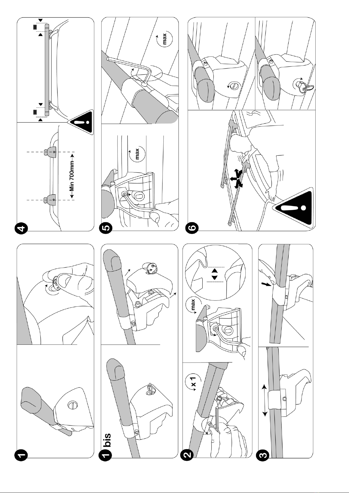
• Se non indicato diversamente dal produttore della vettura, la distanza
minima tra i due supporti dovrebbe essere di 700 mm.
• Caricare il portapacchi uniformemente con un baricentro possibilmente
basso e non superare il carico del tetto indicato dal produttore dell’ auto.
• La portata consentita si compone dal peso proprio del portapacchi (4,7
kg) e dal carico utile.
• La portata consentita del portapacchi è di 75 kg e deve essere distribuita
uniformemente.
• In caso di trasporto di merci lunghe, ssare l’estremità anteriore al
paraurti. Adeguare la velocità al carico.
4. COME CONTATTARCI
EAL GmbH
Otto-Hausmann-Ring 107
42115 Wuppertal, Germania
+49 (0)202 42 92 83 0
+49 (0) 202 42 92 83 – 160
info@eal-vertrieb.com
www.eal-vertrieb.com
INDICE
BASIC PLUS PORTAPACCHI PER MANCORRENTE
1. SPÉCIFICATIONS _______________________________7
2. ISTRUZIONI PER IL MONTAGGIO _____________________7
3. ISTRUZIONI PER L’USO E INDICAZIONI IMPORTANTI _________7
4. COME CONTATTARCI ____________________________7
2. ISTRUZIONI PER IL MONTAGGIO
• Aprire i coperchi a vite con un cacciavite o una moneta.
• Svitare le viti della clip di ssaggio (ill. 2).
• Svitare le viti di regolazione. Mettere i portapacchi sul mancorrente
mantenendo una distanza di ca. 700 mm tra loro.
• Fissare il portapacchi sul mancorrente stringendo leggermente la vite di
regolazione.
• Stringere le viti della clip di ssaggio.
• Stringere le viti di regolazione.
• Controllare la saldezza del ssaggio cercando si smuovere il portapacchi.
• Se necessario, stringere ulteriormente le viti di regolazione.
• Successivamente riapplicare i coperchi a vite e chiudere.
1. SPÉCIFICATIONS
Max. Distanza/spessore della ringhiera: noa 1,10malcentro/ca. 30mm
Altezza minima della ringhiera: ca. 25 mm
Lunghezza del lingotto: ca. 1200 mm
Prolo di supporto (LxP): ca. 35 x 20 mm
Peso proprio: ca. 4,7 kg
Max. capacità di carico: 75 kg
• Rispettare la velocità consigliata indicata. Per evitare danni al tetto
della vettura, il montaggio e lo smontaggio del portapacchi dovrebbe
essere eseguito da due persone.

8
EAL GmbH
Otto-Hausmann-Ring 107
42115Wuppertal
Deutschland
+49 (0)202 42 92 83 0
+49 (0) 202 42 92 83 – 160
info@eal-vertrieb.com
www.eal-vertrieb.com
Table of contents
Languages:
Other EUFAB Automobile Accessories manuals
Popular Automobile Accessories manuals by other brands

Havis-Shields
Havis-Shields Ford Van Rear Air Vent Adapter Kit KK-F-VAK Install instructions

ADOR
ADOR Croco Operation manual

Thermo King
Thermo King V-520 RT Series installation manual

Install Bay
Install Bay IBR65 user manual

ARB
ARB Airlocker RD232 installation guide

Enelion
Enelion LUMINA quick start guide