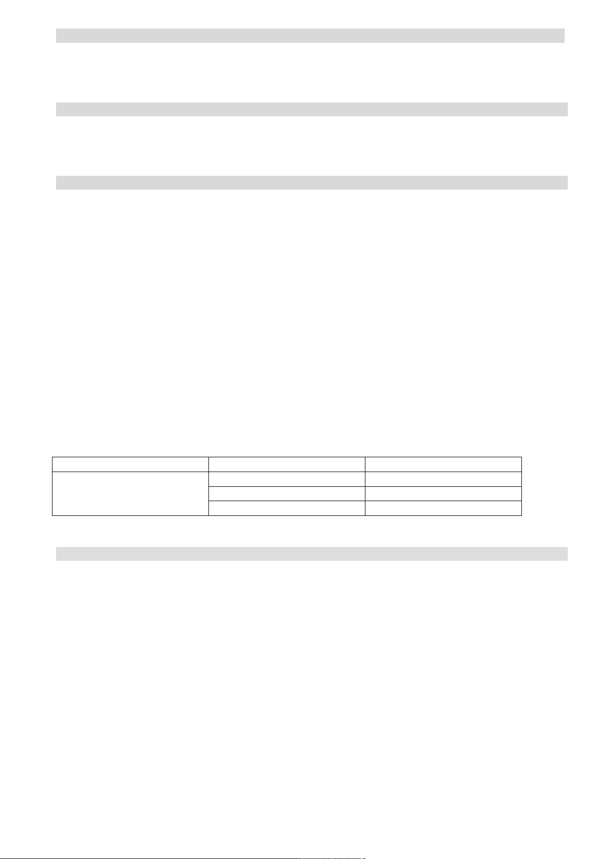
EUFAB Carlo Plus User manual

1
DE
Art. Nr. 11439
Carlo Plus
FAHRRADTRANSPORT AUF DER ANHÄNGERKUPPLUNG
Stützlast
Eigengewicht
Nutzlast
50 kg
17 kg
33 kg
60 kg
17 kg
43 kg
75 kg
17 kg
max. 50 kg
90 kg
17 kg
max. 50 kg
DE GB F I NL CZ SK
EAL GmbH, Otto-Hausmann Ring 107, D-42115 Wuppertal

2
Übersicht
Einleitung
Bestimmungsgemäßer Gebrauch
Spezifikationen
Warnungen und sonstige Hinweise
Bedienungsanleitung
Wartung
Optional erhältlich
Kontaktinformationen
Einleitung
Vielen Dank, daß Sie sich für einen hochwertigen Fahrradträger der Marke EUFAB entschie-
den haben. Wir wünschen Ihnen viel Freude mit diesem Artikel. Vor der Benutzung lesen Sie
unbedingt diese Bedienungsanleitung genau durch. Bewahren Sie die Anleitung zum späte-
ren Nachlesen auf. Bei Weitergabe des Artikels übergeben Sie auch diese Aufbauanleitung.
Bestimmungsgemäßer Gebrauch
Dieser Fahrradträger wird an der Anhängerkupplung von Personenwagen befestigt und ist
zum Transport von zwei Fahrrädern vorgesehen. Der Fahrradträger kann zur Aufnahme eines
dritten Fahrrades erweitert werden. Der Fahrradträger darf unter Berücksichtigung der StVZO
und unter Beachtung der erlaubten Stützlast und der maximalen Nutzlast auch zum Transport
anderer Güter oder Gegenstände verwendet werden, sofern eine sichere Befestigung dieser
Güter oder Gegenstände gewährleistet ist.
Der Fahrradträger ist für Leerfahrten zugelassen und hat nur einen geringen Luftwiderstand.
Dennoch empfehlen wir, den Fahrradträger bei längerem Nichtgebrauch abzunehmen, um
nicht unnötig Kraftstoff zu verbrauchen.
Kupplungsvoraussetzungen
- Die Anhängerkupplung muß bauartgenehmigt sein.
- Kugel und Kugelstange müssen einteilig geschmiedet sein.
- Montieren Sie den Fahrradträger nur an eine Kupplung aus Stahl St52, Grauguß
GGG52 oder besserer Güte.
- Der D-Wert der Kupplungskugel muß mindestens 7,6 kN betragen
- Montieren Sie den Träger nie an einer Kupplung aus Aluminium, anderen Leichtmetallen
oder Kunststoff
Nicht geeignete Kugelstangen aus GGG40 werden von Westfalia hergestellt für folgende
Fahrzeuge:
Hersteller
Prüfsymbol
Passend für
Westfalia
F 4192
Audi A4
F 3830
Audi A6
F 4112
Audi A8
Beachten Sie die Hinweise des Kupplungsherstellers. Im Zweifel fragen Sie direkt beim Her-
steller Ihrer Anhängerkupplung, ob diese geeignet ist.
Sicherheitshinweise und wichtige Informationen
- Die Kugeloberfläche der Anhängerkupplung muß sauber, fettfrei und von jeglichen Lack-
schichten befreit sein.
- Der Fahrradträger setzt sich nach der Befestigung und einigen gefahrenen Kilometern erst
richtig auf die Kupplung. Kontrollieren Sie daher die Befestigung erneut auf sicheren Sitz
hin und stellen Sie dann wenn nötig die Befestigung nach.
- Kontrollieren Sie den Fahrradträger vor dem Gebrauch auf Beschädigungen hin. Beschä-
digte oder verschlissene Teile sind sofort zu ersetzen. Es dürfen nur Originalersatzteile
verwendet werden.
- Veränderungen am Heckträger sind grundsätzlich nicht zugelassen (mechanisch oder
elektrisch). Dies kann sehr gefährlich sein. Gewährleistungsansprüche werden nicht mehr
angenommen und wir können das richtige Funktionieren des Fahrradträgers nicht mehr ga-
rantieren, wenn Modifikationen durchgeführt worden sind. Wir haften nicht für irgendwelche
durch unrichtige Installation, Bedienung oder Modifikation verursachten Schäden.
- Kontrollieren Sie regelmäßig die Beleuchtung Ihres Fahrradträgers auf die korrekte Funkti-
on hin.
- Sorgen Sie immer dafür, daß die Fahrräder mittels der Rahmenhalter und der Radspann-
gurte befestigt sind. Die Rahmenhalter sollen während des Transports abgeschlossen sein.

3
- Achten Sie darauf, daß keine Teile des Fahrrades verloren gehen können (Batterien, E-
Bike-Akkus, Fahrradpumpe, Tachometer, Körbe, Sattel usw.) Entfernen Sie diese Teile zu-
erst, bevor Sie mit dem Fahrradträger fahren!
- Alle Spanngurte und Halterungen des Fahrradträgers auf festen Sitz hin prüfen und bei
Bedarf nachziehen.
- Die Fahrräder nicht durch Planen oder Schutzüberzüge o.ä. abdecken.
- Der Fahrradträger beeinflußt das Fahrverhalten Ihres Fahrzeugs. Passen Sie Ihre Fahrge-
schwindigkeit also an diesen Umstand an (max. 120 km/h). Vermeiden Sie auch ruckartige
Lenk- und Steuerbewegungen.
- Beachten Sie beim Rückwärtsfahren, daß Ihr Fahrzeug länger ist als üblich!
- Es gelten die gesetzlichen Bestimmungen und Vorschriften über die Beförderungen von
Gütern mit Ihrem Fahrzeug.
- Bei Fahrzeugen mit elektronischer Einparkhilfe kann es zu Fehlfunktionen kommen, wenn
der Fahrradträger angebaut ist. Schalten Sie während der Benutzung des Fahrradträgers
die Einparkhilfe aus.
- Falls das Fahrzeug mit einer automatischen Öffnung der Heckklappe ausgestattet ist, sollte
diese ausgeschaltet oder ausschließlich mit der Hand geöffnet werden, wenn der Fahrrad-
träger montiert ist.
- Vor der Benutzung von Autowaschanlagen den Fahrradträger abbauen.
- Der Fahrradträger ist für den Einsatz im Gelände nicht geeignet.
- Wenn der Träger nicht verwendet wird, sollte der Träger von der Anhängerkupplung ent-
fernt werden.
Die Allgemeine Betriebsgenehmigung muß bei angebautem Träger immer im Fahr-
zeug mit geführt werden.
Spezifikationen
Gewicht 17 kg
Nutzlast 33 kg bei 50 kg Stützlast
43 kg bei 60 kg Stützlast
50 kg bei 75 kg Stützlast
50 kg bei 90 kg Stützlast
Elektroanschluß 13-polig
Bedienungsanleitung
Montage des Fahrradträgers
Vormontierter Trägertisch
Blech Schrauben M8 x 50, Scheiben 8 mm, Schraube M16 x 130
Federringe 8 mm Muttern M8
Basis
Basis

4
Entriegeln Sie den Schwenkrahmen, indem Sie die vordere und seitliche Entriegelung lösen.
Ziehen Sie dazu die Bolzen der Verriegelungen ganz heraus und drehen diese um 90° um ein
Wiedereinrasten zu verhindern. Klappen Sie den Schwenkrahmen nach unten. Schrauben
Sie zuerst die Basis an den vormontierten Trägertisch. Das Blech mit der Aufnahme für den
Sicherungsbolzen und den beiden Auflagen für den Schwenkrahmen (siehe Foto) von innen
gegen den äußeren Trägertisch setzen und mit den Schrauben M8 x 50, Scheiben 8 mm, Fe-
derringen 8 mm und Muttern M8 an die Basis schrauben. Die Schrauben werden von innen
nach außen geführt. Bevor Sie die Schrauben fest anziehen, klappen Sie den Schwenkrah-
men zurück und sichern diesen mit beiden Sicherungsbolzen. Drehen Sie nun die Schraube
M16 x 130 ca. 1 cm in die Basis hinein.
Überprüfen Sie anschließend, daß beide Sicherungsbolzen einwandfrei einrasten.
Setzen Sie nun den U–Bügel an die dafür vorgesehenen Rohrhülsen auf und sichern diesen
mit 2 Schloßschrauben M8 x 60, Scheiben 8 mm und den Knaufmuttern M8.
Schieben Sie anschließend die vormontierten, mit dem 13 pol. Stecker versehenen Leuchten-
träger in die Rohre des Schwenkrahmens hinein. Achten Sie darauf, daß sich der Leuchten-
träger mit dem Rückfahrlicht auf der rechten Seite befindet (siehe Foto). Die Leuchtenträger
haben zwei Einstellmöglichkeiten: Bei Fahrzeugen über 1740 mm Breite (siehe Ziffer. 13 im
Leuchtenträger links
Leuchtenträger rechts
U-Bügel
Knaufmuttern M8
Schloßschrauben M8 x 60
Scheiben 8 mm
Muttern M6
Schloßschrauben M6 x 30
Scheiben 6 mm

5
Fahrzeugschein) müssen Sie die Lampenträger in die äußere Position bringen (siehe Foto).
Bei Fahrzeugen unter 1740 mm Breite ist der innere Lochabstand zu wählen. Bevor Sie die
Schloßschrauben M6 x 30 in die Bohrungen einsetzen und anziehen, richten Sie die Leuch-
tenträger zunächst aus und fixieren ihn, indem Sie die zwei dafür vorgesehenen Knebel-
schrauben leicht anziehen. (siehe Foto).
Achten Sie auf eine symmetrische Montage der Leuchten!
Montieren Sie die Radschienen, indem Sie jeweils eine rechte Radschiene in eine linke Rad-
schiene an den Langlöchern übereinander legen (die rechten Radschienen haben an einer
Seite der Schiene eine ausgeprägte Bördelung, siehe Foto). Nehmen Sie für die inneren Boh-
rungen die Schloßschrauben M6 x 20, sowie die Scheiben und Muttern M6, und schrauben
Sie die Radschienen zuerst in der Mitte an den Schwenkrahmen leicht an. Ziehen Sie an-
schließend die Radschienen soweit hinaus, bis Sie die äußeren Bohrungen des
Schwenkrahmens zur Befestigung der Radschienen nutzen können. Befestigen Sie hier die
Radschienen mit den Schloßschrauben M6 x 40. Ziehen Sie nun alle Schrauben der Rad-
schienen sicher und fest an.
Radschienen
Kennzeichenhalter
Ausdrückteile
Schloßschraube M6 x 20 Scheibe 6 mm
Schloßschraube M6 x 40 Mutter M6

6
Montieren Sie den Kennzeichenhalter mit den vormontierten Schrauben und Scheiben so,
daß die Leuchten und der Kennzeichenhalter sich auf einer Höhe befinden.
Wichtiger Hinweis: Die Befestigungskeile für das Kennzeichen befinden sich als Ausdrückteile
im Kennzeichenhalter.
Befestigen Sie das Kabel der Beleuchtungseinheit mit Hilfe der Kabelbinder unterhalb des
Trägertisches. Achten Sie darauf, daß beim Abklappen und Anheben des Fahrradheckträgers
dieses Kabel nicht eingeklemmt oder beschädigt wird.
Drücken Sie nun die Radstopper, je zwei rechts und zwei links, von oben auf die Radschie-
nen. Achten Sie darauf, daß die höher liegende Seite der keilförmigen Stopper zur Trägermit-
te zeigt. Führen Sie nun das kleine Spannband durch die mittlere Öffnung des Radstoppers
hindurch, und führen es unterhalb der Radschiene auf der gegenüberliegenden Seite wieder
durch die mittlere Öffnung zurück (siehe Bild). Die zwei übrig gebliebenen Gurte benötigen
Sie später zusätzlich für die korrekte Befestigung der Fahrräder.
Montage der Rahmenhalter
Lösen Sie die Knaufschraube des Rahmenhalters und drehen Sie sie ganz heraus. Öffnen
Sie die Schelle des Rahmenhalters und legen die Einlagen, an einer für Ihr Fahrrad geeigne-
ten Stelle, um den U–Bügel herum. Legen Sie die Schelle wieder um die Einlagen herum und
drücken sie fest zusammen. Verschließen Sie den Rahmenhalter mit der Knaufschraube
(noch nicht festziehen).
Montage des Fahrradträgers auf der Anhängerkupplung
Achten Sie auf eine unbeschädigte, saubere und fettfreie Anhängerkupplung. Der Fahrradträ-
ger wird von oben auf die Anhängerkupplung gesetzt. Schrauben Sie den Fahrradträger mit
der Schraube M16 leicht fest und richten Sie ihn parallel zum Fahrzeugheck aus. Ziehen Sie
nun die Schraube so fest an, bis der Träger sicher befestigt ist. Überprüfen Sie regelmäßig
den festen Sitz des Trägers auf der Anhängerkupplung, sowie die Befestigung der Fahrräder
am Träger. Überprüfen Sie ebenso regelmäßig die Funktion der Lichtanlage Ihres Fahrradt-
rägers.
Montage der Fahrräder auf dem Heckträger
Das erste Fahrrad wird in die erste Fahrradschiene (dem Fahrzeug am nächsten) gestellt und
mit dem kurzen Rahmenhalter am U–Bügel befestigt. Dazu wird die mit dem Spanngurt ver-
Radstopper
Spanngurt 6 x
Rahmenhalter kurz
Rahmenhalter lang

7
sehene Seite des Rahmenhalters am Fahrradrahmen befestigt. Die Laufräder befestigen Sie,
indem Sie die Radstopper zum Rad schieben, die Spanngurte um die Felge Ihres Fahrrades
legen und die Gurte festziehen. Achtung: Das Vorderrad muß gegen Verdrehen zusätzlich mit
einem kleinen Spanngurt gesichert werden. Dazu wird das Vorderrad nochmals an anderer
Stelle mit der Schiene fest verbunden (siehe
Foto). Das zweite Fahrrad wird üblicherweise entgegengesetzt in die zweite Schiene gestellt
und am U–Bügel mit dem langen Rahmenhalter befestigt. Die Laufräder befestigen Sie eben-
so, wie beim ersten Rad beschrieben. Eventuell ist es erforderlich die Fahrräder individuell
auf dem Heckträger zu versetzen, damit die Rahmenhalter korrekt befestigt werden können.
Sichern Sie nun die Fahrräder mit dem langen Sicherheitsgurt. Legen Sie den Sicherheitsgurt
durch die Fahrradrahmen und um den U-Bügel herum und ziehen den Sicherheitsgurt fest an.
Abklappen des Fahrradträgers
Wenn Sie den Abklappmechanismus bedienen wollen, halten Sie unbedingt mit einer Hand
den U–Bügel fest, damit der Träger nicht schlagartig abklappen kann. Der Abklappmecha-
nismus wir durch einen Sicherungsbolzen auf der linken Innenseite des Trägerrahmens und
einen Bedienhebel in der Mitte des Rahmens arretiert. Zu erst ziehen Sie den Sicherungsbol-
zen auf der linken Seite bis zum Anschlag heraus und verdrehen ihn ein wenig, damit er nicht
zurück schnappt. Jetzt drehen Sie den Griff des Bedienhebels bis zum Anschlag nach rechts
und ziehen den Hebel zu sich nach hinten.
Der Träger kann nun vorsichtig abgeklappt werden. Durch Anheben des Trägertisches und
Verriegeln des Bedienhebels kommt dieser wieder in die Betriebsposition. Der Sicherungs-
bolzen auf der linken Seite muß unbedingt wieder sicher eingerastet werden, um einen siche-
ren Halt zu gewährleisten.
Achtung!
Durch die Öffnung am Trägertisch können Sie sehen, ob der Trägertisch korrekt verriegelt
oder entriegelt ist.
zweiter Gurt
Sicherheitsgurt
gesichert
nicht gesichert

8
Achtung!
Vergewissern Sie sich, daß beide Sicherungsbolzen eingerastet sind und den Abklappme-
chanismus blockieren, bevor Sie ihre Fahrt fortsetzen!
Wartung
!Reinigung mit einem trockenen, weichen Tuch
!Schlamm und anderen Schmutz eventuell mit Wasser abspülen
!Den Fahrradträger nach Verwendung sauber und trocken lagern
!Die Anhängerkupplung sauber und fettfrei halten
!Die Trägerkupplung sauber und fettfrei halten
!Den Träger regelmäßig auf Beschädigungen kontrollieren. Beschädigte oder verschlissene
Teile sind sofort zu ersetzen. Es dürfen nur Originalersatzteile verwendet werden
!Bolzen und Muttern des Fahrradträgers regelmäßig kontrollieren und wenn notwendig
nachziehen
!Lackbeschädigungen sofort ausbessern
!Drehbare und bewegliche Teile regelmäßig schmieren
Optional erhältlich:
Art. Nr. 11446 Erweiterungssatz für das 3. Fahrrad
Art. Nr. 11402 einen Schnellverschluß für die schnelle und einfache Montage auf die Anhän-
gerkupplung.
Art. Nr. 11232 abschließbarer Rahmenhalter 115 mm
Art. Nr. 11234 abschließbarer Rahmenhalter 180 mm für das 3. Rad
Art. Nr. 11233 abschließbarer Rahmenhalter 310 mm
Die Befestigung für das 3. Rad erfolgt von Fahrrad zu Fahrrad. Daher benötigen Sie noch
zusätzlich den abschließbaren Rahmenhalter 11234. Der Rahmenhalter wird zu diesem
Zweck beidseitig mit großen Klammern ausgerüstet. Dieser zusätzliche Klammersatz gehört
zum Lieferumfang.
Art. Nr. 11442 Keilscheibe
Bei einigen Kupplungstypen kann es vorkommen das sich der Trägertisch etwas zur Straße
neigt. Um diese unerwünschte Neigung auszugleichen, bieten wir eine Keilscheibe an, die
zwischen der Basis und dem Trägertisch montiert wird
Art. Nr. 11441 Adapterplatte
In einigen Fällen ist es notwendig den Abstand von Anhängekupplung zum Trägertisch zu
vergrößern, um die Heckklappe des Fahrzeugs öffnen zu können. Dazu benötigen Sie die
Adapterplatte.

9
Die vorgenannten Teile sind untereinander kombinierbar. Alle Zubehörteile werden mit dem
nötigen Befestigungsmaterial ausgeliefert. Original Umbauteile sind selbstverständlich ge-
nehmigt und zugelassen.
Hinweise zum Umweltschutz
Bitte entsorgen Sie dieses Gerät über die Wertstofftonne oder die öffentlichen/kommunalen
Sammelstellen.
Die Materialien sind recycelbar. Durch Recycling, stoffliche Verwertung oder andere Formen
der Wiederverwendung von Altgeräten leisten Sie einen wichtigen Beitrag zum Schutz unse-
rer Umwelt!
Kontaktinformationen
EAL GmbH
Otto-Hausmann-Ring 107
42115 Wuppertal
Deutschland
Telefon: +49 (0)202 42 92 83 0
Telefax: +49 (0)202 2 65 57 98
Internet: www.eal-vertrieb.de
E-Mail: info@eal-vertrieb.com
GB
Art. No. 11439
Carlo Plus
TRANSPORTING CYCLES ON THE TOWBAR
Assembly instructions
Dear customer,
thank you for purchasing this product. This rear cycle rack has been checked to see it is com-
plete. The rear rack is epoxiert, and the hollow spaces are coated inside which prevents the
metal rusting. If this coating is impaired in any way (scratched, damaged), ensure that the
protection is repaired!
Before starting to assemble the product, ensure that the rear cycle rack is complete and read
the assembly instructions carefully; observe the safety information. Please remember that
some of the parts included in the parts list have already been pre-assembled. Subject to
technical amendments.
Towbar conditions for the cycle rack Carlo Plus
The cycle rack can be mounted onto all towbar balls under the following conditions.
The maximum useful load of the cycle rack is: 50 kg
Test the suitability of the towbar.
The towbar type must have been officially approved.
The ball and towbar itself need to be cast as one part.
The towbar material must have a minimum quality of St 52-3.
Supporting load
Deadweight
Useful load
50 kg
17 kg
33 kg
60 kg
17 kg
43 kg
75 kg
17 kg
max. 50 kg
90 kg
17 kg
max. 50 kg
Note: Usually the towbars are made of St 52-3. Cast material such as e.g. GGG 40 is not
suitable (only suitable from GGG 52 upwards). Not suitable for aluminium towbars. The fol-
lowing towbars are currently made of GGG 40: If in doubt ask the manufacturer of the towbar.
Manufacturer of the towbar
Test symbol
Suitable for vehicle type
F 4192
Audi A4
Westfalia
F 3830
Audi A6
F 4112
Audi A8

10
Assembly picture 1
All screws should be treated with oil or grease to ensure long-term easy movement. First,
screw the base to the pre-assembled carrier table. Fold the swing frame downwards by first
unlocking the securing mechanism at the side. The plate with the receptacle for the securing
bolt as well as both rests for the swing frame (see photo) must be placed up against the outer
carrier table and screw the base into place using the M8 x 50 screws, 8 mm washers and M8
nuts. The screw heads should all go from inside to out. Before tightening the screws up, fold
the swing frame back and secure using the two securing bolts. Now screw the M16 x 130
screw approximately 1 cm into the base. Then check to make sure that both securing bolts
can be shot home.
Assembly picture 2
Place the U – bracket onto the designated tube sleeves and secure with 2 lock screws, (M8 x
60) washers (8 mm) and knurled nuts (M8). Insert the pre-assembled lamp holders with the
13-wire plug into the end of the tube of the swivel frame. Ensure that the lamp holder with the
reverse light is on the right (see photo). The lamp holders have two setting options. For vehi-
cles that are wider than 1740 mm (see section 13 in the car documents), the lamp holders
need to be mounted in the outer position (see photo). For vehicles that are less wide than
1740 mm, the inner hole distance needs to be selected. Align the lamp holder with the 2 des-
ignated knurled screws and insert the lock screws (M6 x 30) into the bore-holes (see photo –
slightly tighten the knurled screw).
Ensure that the lamps are mounted symmetrically.
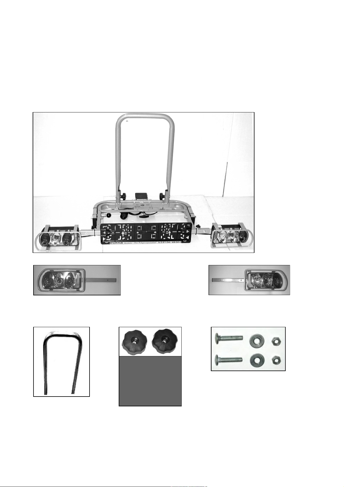
Assembly picture 3
Assemble the wheel rails by placing the right wheel rail into a left wheel rail at the long holes.
The right wheel rails have a raised beaded edge on one side of the rail (see photo). Use the
short screws, washers and securing nuts for the inner bore-holes. First loosely screw the wheel
rails to the swivel frame in the central position. (lock screws M6 x 20, washer and Nut M6). Pull
out the wheel rails until the outer bore-holes of the swivel frame can be used for attachment
purposes. Secure and tighten all screws on the wheel rails.
Important information:
The attachment parts for the registration plate holder are enclosed as press-out parts in the
registration plate holder itself. Attach the cable of the lighting unit using the cable tie below the
support table. Ensure that this cable is not caught or damaged when the cycle rack is folded
up or down.
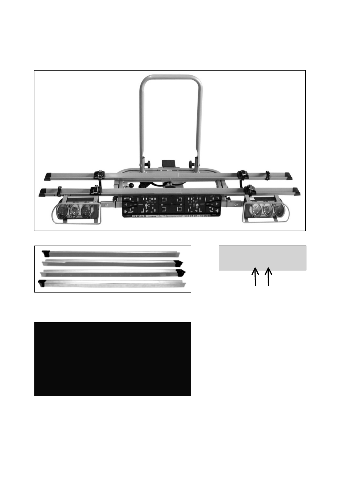
Press the stoppers onto the wheel rail from the top, 2 on the right and 2 on the left. Ensure
that the higher side of the wedge shape is pointing towards the centre of the carrier. Now
thread the small strap through the middle hole on the stopper and under the wheel rail to the
opposite side, back through the middle hole. You will also need the 2 remaining belts later, in
order to fix the bikes correctly. Open the frame holder clips and place these around the U-bolt
with the insets. Reclose the clips using the finger screw. (Do not yet tighten).
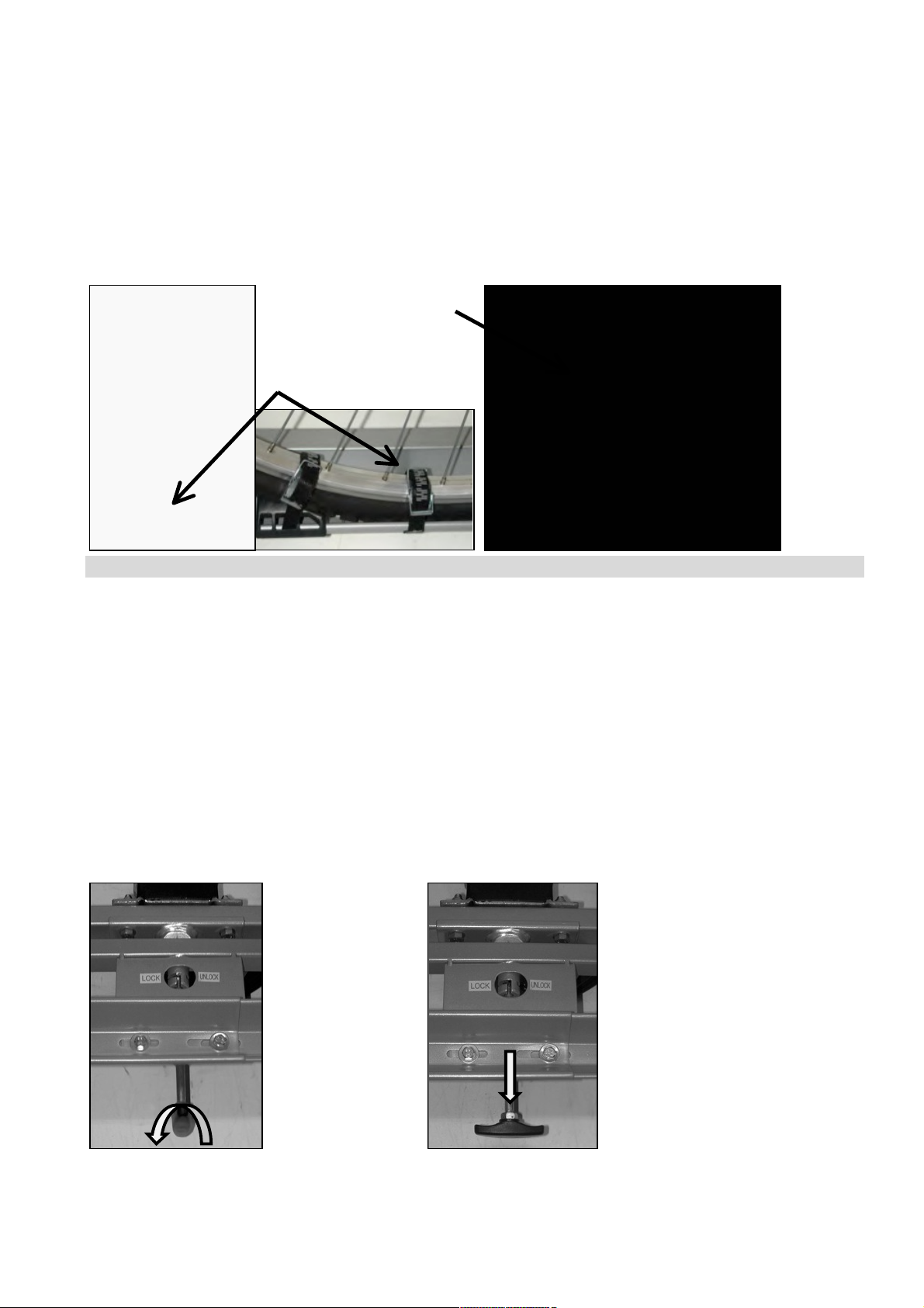
Assembly of the cycle rack onto the towbar
Ensure that the towbar is undamaged, clean and free of grease. The cycle rack is placed on
the towbar from above. Loosely screw the cycle rack with the screw M16 and align parallel to
the rear of the vehicle. Tighten the screw M16 using the supplied key until the rack is attached
securely. Check that the rack is securely on the towbar and that the cycles are firmly in
position on the rack. Check the function of the cycle rack lighting system regularly.
Fixing the bikes to the rear bike carrier
Place the first bike in the first bike rail (nearest to the vehicle) and fix it on the U-bolt using the
short frame holder.
Fix the running wheels by pressing the stoppers to the wheel and tightening the belt.
Caution: the front wheel must also be secured with a small strap to prevent it from
turning. See photograph.
Here, the frame holder clip is used for fixing on the U-bolt and the strap opposite for fixing on
the bike. The second bike is normally to be placed in the second rail in the opposite direction
Plate

11
and fixed to the U-bolt with the long frame holder. Fix the running wheels as described for the
first wheel.
It may be necessary to place the bikes individually on the rear carrier, rather than as de-
scribed, so the frame holders can be fixed correctly. Now secure the bikes using the long
safety belt. For additional safety, run the safety belt through the bike frame and around the U-
bolt and tighten firmly.
Folding down the cycle rack
Hold the U –bracket with one hand so that the rack does not fold down suddenly. With the
other hand, turn the side securing bolt and pull this outside. Unlock the central securing bolt
and the rack can be folded down. If the rack table is lifted, this will click back into its working
position again. Turn the securing bolt until it clicks into position.
Caution: you can see through the opening on the carrier table whether the carrier table is
locked or unlocked correctly.
Caution:
The safety instructions must be observed!
Observe the authorised axle load.
Before starting each journey and at regular intermediate intervals, check that the carrier is
sitting firmly on the vehicle and that the wheels are properly fixed to the carrier, in order to
detect and rectify any damage to the fixing elements at an early stage.
Before starting each journey and at regular intermediate intervals, verify the correct function
of the lighting system on your rear carrier.
With new hitches, there is frequently a thick black layer of paint on the tow ball. In order for
your rear carrier to gain the best possible grip, this layer of paint should be removed, using
corrosive fluid, solvents etc.
The load must not protrude sideways over the lighting by more than 400 mm.
The load must be fixed from the safety belt!
Parts that can be lost, e.g. such as air pumps, baskets, bells etc must be removed before
starting the journey.
Driving with a bike carrier affects the driving characteristics of a vehicle. You should therefore
adjust your driving speed. Avoid sudden and jerky steering movements.
When reversing, note that the carrier makes your vehicle longer than normal!
When not in use, the bike carrier should be removed.
When transporting bikes, do not cover with a blanket or similar.
The maximum speed is 130 Km/h
For proper and safe fitting, follow the fitting instructions precisely. If in doubt when referring to
these instructions, ask the dealer or the manufacturer directly for further information. For your
own safety, regularly check the carrier and its loading, as you are obliged to do so under § 23
of the German highway code and will be held liable in the event of damage.
The manufacturer and dealer will not be liable for damages to property or injuries to people
caused by incorrect fitting or improper use.
Not clicked into
position
Clicked into position and secured!

12
The product has been tested and tried even under extreme conditions and produced good
results with respect to safety and grip. We are therefore able to exclude malfunctions if the
fitting has been carried out correctly.
Dear Customer, in observance of the German highway code and the existing bearing load
and max. loading capacity, this rear bike carrier may also be used for transporting other
goods or objects. However, secure fixing of these goods or objects must be guaranteed.
The carrier may be modified using original parts, for example:
(needs to be ordered separately)
Art. No. 11446 expansion set for the 3rd cycle
Art. No. 11402 a quick release fastener for fast and simple assembly to the towbar.
Art. No. 11232 lockable frame holder 115mm
Art. No. 11234 lockable frame holder 180mm for the 3rd cycle
Art. No. 11233 lockable frame holder 310mm
And because the attachment for the 3rd cycle involves attachments from cycle to cycle, you
will also need the lockable frame holder 11234. This frame holder can be fitted with large clips
on both sides. This set of clips is included in the delivery scope.
Art. No. 11442 wedge washer
In the case of some towbars, the rack table may tilt somewhat toward the road surface. To
compensate this tilt, we also supply a wedge washer which is position between the base and
the rack table.
Art. No. 11441 adapter plate to increase the distance from the towbar to the rack table in case
the boot of the car cannot be opened.
All these parts can be combined with each other and will be supplied with the required at-
tachment materials. All original conversion parts are officially approved. Please observe the
assembly instructions to ensure proper and secure assembly.
If in doubt with regard to these instructions, please contact your dealer or the manufacturer for
further information.
The manufacturer and the dealer will not be liable for damage or injury caused by in-
correct assembly or improper use.
Wedge
washer
Wedge washer
Rack table
Base

13
F
N° d'art. 11439
Carlo Plus
TRANSPORT DE VELOS SUR L'ACCOUPLEMENT DE REMORQUE
Instructions de montage
Chère cliente/cher client,
merci d'avoir opté pour ce produit. Ce porte-vélos arrière a été contrôlé quant à son intégrali-
té. Le porte-vélos est revêtu d'une couche d'époxy pour que le métal résiste bien à l'oxyda-
tion; les creux sont également protégés contre la corrosion. Au cas où la couche de protec-
tion serait endommagée d'une manière ou d'une autre (rayures ou traces de chocs), veuillez
la soumettre à une retouche !
Avant le montage, vous devrez vérifier que le porte-vélos arrière est au complet. En outre,
vous devrez lire attentivement les instructions de montage et observer à la lettre les con-
signes de sécurité. N'oubliez pas que certaines pièces figurant dans la liste des pièces ont
déjà été montées. Sous réserve de modifications techniques.
Conditions d'accouplement du porte-vélos Carlo Plus
Le porte-vélos peut être monté sur n'importe quelle boule d'attelage lorsque les conditions
suivantes sont remplies.
La charge utile maximale du porte-vélos est de 50 kg.
L'accouplement de remorque doit se prêter à l'attelage du porte-vélos.
Le type d'accouplement de remorque doit être homologué.
La boule et le coude portant la boule doivent être forgés d'une seule pièce.
Le matériau de la boule d'attache doit être d'une qualité minimale de St 52-3.
Charge d'appui
Propre poids
Charge utile
50 kg
17 kg
33 kg
60 kg
17 kg
43 kg
75 kg
17 kg
max. 50 kg
90 kg
17 kg
max. 50 kg
Remarque:
Normalement, les boules d'attelage sont fabriquées en acier St 52-3. Le matériau coulé tel
que par ex. la fonte GGG 40 n'est pas approprié (aptitude à partir de GGG 52).
Si les accouplements de remorque sont en aluminium, l'attelage n'est pas possible. De nos
jours, les boules d'attelage suivantes sont fabriquées en fonte GGG 40: en cas de doute,
veuillez contacter le fabricant de l'accouplement
Fabricant de l'accouplement de remorque
Marque d’épreuve
Approprié pour
F 4192
Audi A4
Westfalia
F 3830
Audi A6
F 4112
Audi A8
Montage photo 1
Toutes les vis devraient être traitées avec de l'huile ou de la graisse afin de garantir une facili-
té d'emploi durable. Vissez d'abord la base sur la table support prémontée. Rabattez vers le
bas le cadre oscillant après avoir déverrouillé d'abord la sécurité latérale. Positionnez, depuis
l'intérieur, la tôle avec l'évidement pour la goupille de sécurité ainsi que les deux appuis pour
le cadre oscillant (cf. photo) contre la table support extérieure et vissez la base avec les vis
M8 x 50, les rondelles de 8 mm et les écrous M8. Les vis doivent être introduites du dedans
vers le dehors. Avant de serrer à fond les vis, rabattez le cadre oscillant en arrière et bloquez
celui-ci avec les deux goupilles de sécurité. Tournez maintenant la vis M16 x 130 d'environ 1
cm dans la base. Vérifiez ensuite que les deux goupilles de sécurité s'enclenchent correcte-
ment.

14
Montage photo 2
Placez l'étrier en U sur les tubes prévus à cet effet et bloquez-le au moyen de 2 vis à tête
ronde M8 x 60 et des rondelles 8 mm et écrous moletés M8.
Montez le connecteur à 13 points sur le porte-feu prémonté et introduisez ce dernier dans les
bouts des tubes du cadre basculant. Veillez á ce que le porte-feu arrière soit du côté droit (cf.
photo). Les porte-feu offrent deux possibilités de réglage. Pour les véhicules de plus de 1740
mm de largeur (cf. chiffre 13 dans le certificat d'enregistrement du véhicule), les porte-feu
doivent être montés sur la position extérieure (cf. photo). Pour les véhicules de moins de
1740 mm de largeur, il faut opter pour les trous de fixation intérieurs. Alignez les porte-feu au
moyen des 2 vis moletées prévues à cet effet et introduisez les vis à tête ronde (M6 x 30)
dans les perçages (cf. photo – serrez les vis moletées légèrement). Veillez à qu'après le mon-
tage, les feux soient symétriques.
Montage photo 3
Montez le rail porte-vélo, assemblez le rail porte-vélo de droite dans un rail porte-vélo gauche
au niveau des trous oblongs. Les rails porte-vélo de droite sont nettement sertis d'un côté (cf.
photo). Utilisez pour le trou intérieur les vis à tête ronde (M6 x 20) courtes ainsi que les ron-
delles et les écrous de blocage (M6). Vissez d'abord légèrement les rails porte-vélo d'abord au
milieu sur le cadre basculant. Extrayez les rails porte-vélo jusqu'à ce que vous pouvez utiliser
les perçages extérieurs du cadre basculant afin de fixer. Serrez à fond toutes les vis des rails
porte-vélo.
Remarque importante:
Les cales de fixation de la plaque d'immatriculation sont estampées dans le porte-plaque
d'immatriculation et peuvent en être chassées. Fixez le câble de l'unité d'éclairage au moyen
du serre-câbles sous le table support. Veillez à ce que ce câble ne soit pas coincé ou en-
dommagé lors de l'abaissement ou de la montée du porte-vélos arrière.
Puis pressez 2 stoppeurs respectivement à la droite et 2 à la gauche de l’haut sur les rails.
Faites attention à ce que la partie du coin qui se trouve plus haute montre au centre du por-
teur. Introduisez maintenant la sangle petite à travers l’ouverture du stoppeur. Ensuite met-
tez-la du côté opposé au-dessous du rail et posez cette sangle à travers l’ouverture centrale
pour la ramener (voir dans l’image). Vous aurez besoin des 2 ceintures restantes pour pou-
voir attacher les bicyclettes correctement plus tard. Ouvrez maintenant les clips du porteur de
cadre et posez ceux-ci avec les pièces intercalaires autour de l’étrier. Puis fermez les clips
avec les vis moletées (mais ne les serrez pas encore à fond).
Montage des vélos sur le porte-vélos arrière
Posez la première bicyclette dans le premier rail (qui se trouve le plus proche du véhicule) et
attachez-la à l’étrier avec le porteur de cadre court.
Fixez les roues en poussant les stoppeurs contre les roues de la bicyclette et en y serrant les
ceintures à fond. Attention: En plus, il vous faut consolider la roue avant avec la sangle petite
pour éviter qu’elle tourne à droite ou à gauche pendant le transport. Voir dans la photo.
Puis attachez le clip du porteur de cadre à l’étrier et la sangle opposée à la bicyclette. Posez
après la deuxième bicyclette le mieux inversément dans le deuxième rail. Attachez-la ensuite
à l’étrier avec le porteur de cadre long. Fixez les roues de cette bicyclette comme décrit ci-
dessus pour la première bicyclette.
Peut-être qu’il sera nécessaire de poser les bicyclettes individuellement et alternativement
dans le porteur arrière pour que les porteurs de cadre puissent être fixés correctement. Atta-
chez les bicyclettes avec la ceinture de sécurité longue en la posant à travers les cadres des
bicyclettes et autour de l’étrier. Serrez ensuite cette ceinture de sécurité fermement.
Montage du porte-vélos sur l'accouplement de remorque
Veillez à ce que l'accouplement de remorque soit en bon état (non endommagé), propre et
exempt de graisse. Placez le porte-vélos de par le haut sur l'accouplement et vissez-le légè-
rement au moyen de la vis M16; le porte-vélos doit être parallèle à l'arrière du véhicule. Ser-
rez à fond la vis au moyen de la clé fournie (env. 100 Nm ) afin d'obtenir une fixation stable et
sûre du porte-vélos. Contrôlez l'attelage correct du porte-vélos ainsi que la fixation des

15
vélos sur le porte-vélos. Le fonctionnement de l'unité d'éclairage du porte-vélos doit
être vérifié régulièrement.
Descente du porte-vélos
Maintenez d'une main l'étrier en U pour que le porte-vélos ne se rabatte pas brusquement.
De l'autre main, vous tournerez en premier lieu le boulon de sécurité latéral et vous devez
ensuite le retirer. Débloquez le boulon de sécurité central pour ensuite rabattre le porte-vélos.
En soulevant la table support, celle-ci reprend de nouveau la position d'utilisation. Tournez les
boulons de sécurité jusqu'à ce qu'ils s'encliquètent.
Attention !
A travers l’ouverture de la plateforme, vous pouvez vérifier si le plateau est correctement ver-
rouillé ou déverrouillé.
Attention :
Suivez absolument ces instructions de sécurité.
Tenez compte de la charge par essieu admissible de votre véhicule.
Contrôlez toujours avant de partir et aussi entretemps régulièrement si le porteur est monté
fixément au véhicule et si les bicyclettes sont encore montées fermement sur le porteur. C’est
ainsi que vous pouvez noter et dépanner précocement un endommagement possible des
éléments de fixation.
Contrôlez aussi régulièrement avant de partir si les phares de votre porteur marchent bien.
Sur la boule des dispositifs d’attelage de remorque nouveaux il y a souvent un revêtement
épais de vernis noir. Pour que votre porteur arrière aie le plus de solidité ôtez le mieux ce
vernis avec du décapant, du solvant, etc.
La charge du porteur ne doit pas dépasser les phares de plus de 400 mm sur les côtés.
Attachez toujours la ceinture de sécurité après avoir chargé le porteur.
Enlevez des accessoires qu’on pourrait perdre facilement comme la pompe à vélo, la sa-
coche ou le panier avant de partir en route.
Tenez compte du fait que le porteur influencera le maniement de votre voiture. Adaptez donc
votre vitesse aux conditions changées et évitez surtout des mouvements soudains et sacca-
dés du volant.
Si vous réculez, tenez compte de que votre voiture avec le porteur monté est plus longue que
normalement.
Quand vous ne l’utilisez pas, démontez votre porteur du véhicule.
Ne couvrez pas les bicyclettes d’une bâche avant de les transporter.
La vitesse maximale de la voiture avec porteur monté s’élève à 130 km/h.
Suivez scrupuleusement ces instructions de montage pour assurer un montage régulier et
solide. En cas de doute en ce qui concerne ces instructions demandez des informations sup-
plémentaires chez le vendeur ou bien directement chez le fabricant. Pour assurer votre sécu-
rité contrôlez le porteur et sa charge régulièrement parce que le code de la route vous y
oblige et vous pouvez être rendus responsable en réalisation du sinistre.
Encliqueté et sécurisé !
Pas encliqueté – le cadre basculant descend !

16
Ni le fabricant ni le vendeur ne répondent de dégâts matériels ou de dommages corporels par
suite d’un montage incorrect ou un usage qui n’est pas approprié.
Ce produit a été testé et mis à l’épreuve sous des conditions extrèmes et nous avons obtenu
de bons résultats de sécurité et de solidité. Donc, nous pouvons exclure tout fonctionnement
incorrect à condition que le porteur aie été monté correctement.
Cher client,
vous pouvez utiliser ce porteur de bicyclettes aussi pour les transports d’autres biens ou ob-
jets, si vous tenez compte du code de le route, du poids sur le dispositif d’attelage de re-
morque et de la charge utile maximale. Toutefois vous devez toujours assurer que les biens
ou objets soient fixés biens.
Vous pouvez également modifier la structure de ce support avec des pièces d'origine, à sa-
voir avec:
(passation de commande supplémentaire requise)
N° d'art. 11446 - kit d'extension pour un 3ème vélo
N° d'art. 11402 une fermeture instantanée pour le montage rapide et simple sur l'accouple-
ment de remorque.
N° d'art. 11232 fixe-cadre verrouillable 115 mm
N° d'art. 11234 fixe-cadre verrouillable 180 mm pour le 3ème vélo
N° d'art. 11233 fixe-cadre verrouillable 310 mm
Vu que la fixation du 3ème vélo se fait entre les vélos, vous avez besoin aussi du fixe-cadre
verrouillable 11234. Ce fixe-cadre peut être équipé de grandes pinces des deux côtés. Le kit
de pinces supplémentaire fait partie de la fourniture.
N° d'art. 11442 Cale
Quelques types d'accouplements peuvent faire s'incliner un peu la table support vers la
chaussée. Pour compenser, nous proposons une cale qui doit être insérée entre la base et la
table support.
N° d'art. 11441, une plaque adaptatrice qui élargit la distance entre le dispositif d’attelage et
la table porteuse si le hayon ne peut pas être ouvert.
Cale
Cale
Table
support
Base

17
Tous ces éléments peuvent être combinés entre eux et ils sont livrés avec les accessoires de
fixation nécessaires. Tous les éléments de modification ont été admis et autorisés. Pour un
montage régulier et solide suivez péniblement les instructions.
En cas de doute en ce qui concerne ces instructions demandez des informations supplémen-
taires chez le vendeur ou directement chez le fabricant. Pour votre sécurité contrôlez le por-
teur et sa charge régulièrement, parce que le code de la route vous y oblige et vous pouvez
être rendus responsable en réalisation du sinistre. Le fabricant et le vendeur ne répondent
pas de l’endommagement d’objets et de personnes à cause d’un montage ou un usage qui
n’est pas approprié.
Nous avons testé et mis à l’épreuve ce produit sous des conditions extrèmes et nous avons
obtenu de bons résultats en ce qui concerne la sécurité et la solidité. Ainsi nous pouvons ex-
clure tout fonctionnement incorrect si le porteur a été monté correctement.
I
Codice 11439
Carlo Plus
TRASPORTO DALLA BICICLETTA SUL GANCIO DEL RIMORCHIO
Istruzioni per il montaggio
Gentile cliente,
molte grazie per essersi deciso all'acquisto di questo prodotto. Questo supporto posteriore
per biciclette è stato verificato sulla completezza. Il supporto posteriore è epossidato, mentre
le cavità sono rispettivamente rivestite, prevenendo così una ossidazione del metallo. In caso
di qualsiasi genere di danneggiamento di questi rivestimenti (graffi, urti), si raccomanda di
ripristinare al più presto possibile la protezione!
Prima di iniziare i lavori di montaggio, si raccomanda di verificare la completezza del supporto
posteriore per biciclette e leggere attentamente le istruzioni per il montaggio è osservare
scrupolosamente le avvertenze di sicurezza. È da tener presente che alcuni componenti ri-
portati nella lista dei pezzi sono già premontati. Ci riserviamo il diritto di apportare modifiche
tecniche.
Condizioni di accoppiamento per il supporto di biciclette Carlo Plus
Il supporto per biciclette può essere montato su ogni sfera d'accoppiamento rispettando le
condizioni seguenti.
Il carico massimo del supporto per biciclette corrisponde a: 50 kg
Verificare l'attitudine del gancio per rimorchi
Il gancio per rimorchi deve essere comunque omologato.
La sfera e la barra di traino devono essere fucinate in un lato.
Il materiale della barra a sfera deve presentare una qualità minima di St 52-3.
Carico del timone
Peso proprio
Carico utile
50 kg
17 kg
33 kg
60 kg
17 kg
43 kg
75 kg
17 kg
max. 50 kg
90 kg
17 kg
max. 50 kg
Nota:
Di regola le barre a sfera realizzate in materiali di ghisa St 52-3., ad esempio GGG 40, non
sono adatte. ( sono adatte solo le varianti a partire da GGG 52 ).
Non adatto per accoppiamenti d'alluminio. Attualmente vengono fabbricate le seguenti barre a
sfera in GGG 40: In caso di dubbi, interpellare il costruttore dell'accoppiamento

18
Costruttore del
Marchio di controllo
adatto per
gancio rimorchio
Tipo veicolo
F 4192
Audi A4
Westfalia
F 3830
Audi A6
F 4112
Audi A8
Montaggio figura 1
Tutte le viti dovrebbero essere trattate con olio o grasso per garantire una scorrevolezza du-
revole. Avvitare dapprima la base al tavolo di supporto premontato. Abbassare il telaio orien-
tabile sbloccando precedentemente il fermo laterale. Applicare dall’interno la lamiera con
l’alloggiamento dei bulloni di sicurezza e i due supporti del telaio orientabile (vedi foto) contro
il tavolo di supporto esterno e avvitare la base con le viti M8 x 50, rosette da 8 mm e dadi M8.
Le viti devono essere inserite dall’interno verso l’esterno. Prima di stringerle, risollevare il te-
laio orientabile e bloccarlo con i due bulloni di sicurezza. Ora avvitare la vite M16 x130 nella
base per ca. 1 cm. Controllare infine se i due bulloni di sicurezza sono fissati saldamen-
te.
Montaggio figura 2
Inserire la staffa a U sulle boccole tubolari appositamente previste e bloccarla quindi per
mezzo di due viti di serraggio M8 x 60, con le rondelle 8 mm e i dadi zigrinati M8.
Spingere i portalampada premontati con il connettore a 13 poli nelle estremità tubolari del
telaio orientabile. Accertarsi che il portalampada con il fanalino posteriore si trovi sulla parte
destra (si veda alla foto). I portalampada offrono due possibilità di regolazione. In automezzi
con una larghezza di oltre 1740 mm (si veda la cifra 13 nel libretto di circolazione) i portalam-
pada devono essere montati nella posizione esterna (si veda alla foto). In automezzi con una
larghezza inferiore a 1740 mm è da scegliere la distanza interna dei fori. Allineare il porta-
lampada per mezzo delle due viti di serraggio M6 x 30 appositamente previste e inserire
quindi le viti dei rispettivi fori (si veda alla foto - stringere leggermente le viti zigrinate). Accer-
tarsi di un montaggio simmetrico delle lampade.
Montaggio figura 3
Montare le guide delle ruote, inserire la guida della ruota destra in una guida della ruota sini-
stra insieme nei fori oblunghi. Le guide delle ruote destre in un lato della guida sono dotate di
una bordatura (si veda alla foto). Per i fori interni utilizzare le viti di serraggio M6 x 20, le ron-
delle e i dadi di sicurezza M6. Avvitare leggermente le guide delle ruote prima nella posizione
centrale sul telaio orientabile. Estrarre le guide delle ruote fino ad un punto tale da poter utiliz-
zare i fori esterni del telaio orientabile per il fissaggio. Stringere tutte le viti delle guide delle
ruote con la massima sicurezza.
Nota importante:
I cunei di fissaggio per la targa si trovano nel portatarga dove possono essere spezzati fuori.
Il cavo dell'unità di illuminazione deve essere fissato con l'ausilio di fascette serracavo nel
situato al di sotto tavola di supporto. Accertarsi al rivoltamento e sollevamento del sup-
porto per biciclette di non schiacciare questo cavo o danneggiarlo in altro modo.
Adesso apllicare i fermi, 2 a destra e 2 a sinistra, sulle corsie per alloggiamento ruote, a parti-
re da sopra. Far attenzione che la parte superiore del mozzetto sia diretta verso il centro del
portabicicletta. Inserire adesso la piccola cinghia di fissaggio attraverso l’apertura centrale dei
fermi e riportarla indietro attraverso l’apertura centrale, facendola passare al di sotto
dell’alloggiamento ruote della bicicletta, sul lato frontale. (Vedere immagine). Le 2 cinghie re-
stanti saranno necessarie più tardi, per il corretto bloccaggio delle biciclette. Aprire le morse
del supporto telaio e porle con l’inserto intorno al ferro a U. Chiudere le morse con le viti a
testa zigrinata. (per il momento non stringere).
Montaggio delle biciclette sul supporto posteriore
La prima bicicletta deve venir collocata sulla prima corsia per alloggiamento ruote della bici-
cletta (la più vicina all’autoveicolo) e fissata al ferro a U per mezzo di 2 piccole cinghie di fis-
saggio.

19
Le ruote della bicicletta si bloccano nel momento in cui vengono applicati i fermi delle ruote
della bicicletta sulle ruote stesse e le cinghie di fissaggio vengono tirate.
Attenzione: la ruota anteriore della bicicletta deve essere assicurata, per ,ezzo di tor-
sione, con una piccola cinghia di fissaggio. Vedere immagini.
La morsa del telaio della bicicletta viene utilizzata per il fissaggio della bicicletta al ferro a U e
alla cinghia di fissaggio posta frontalmente. La seconda bicicletta viene normalmente posta di
fronte all’altra sulla seconda corsia per alloggiamento ruote della bicicletta e viene bloccata al
ferro a U per mezzo del portatelaio lungo. Le ruote della bicicletta vengono fissate come già
descritto per quelle della prima bicicletta.
A volte è possibile che le biciclette debbano venire posizionate sul portabicicletta in un altro
modo rispetto a quello descritto, in modo che i portatelai possano essere fissati in modo cor-
retto. Adesso fissare le biciclette con la cinghia di fissaggio lunga. Adagiare la cinghia di fis-
saggio attraverso i telai delle biciclette ed intorno al tubo a U e tirare forte la cinghia di fissag-
gio.
Montaggio del supporto per biciclette sul gancio del rimorchio
Accertarsi che il gancio del rimorchio sia intatto, ben pulito e privo di grasso. Il supporto per
biciclette viene fissato dall'alto sul gancio del rimorchio. Stringere leggermente il supporto per
biciclette con la vite M16 e allinearlo quindi in parallelo rispetto alla parte posteriore dell'auto
mezzo. Stringere la vite con la chiave fornita in dotazione fino ad un punto tale (ca. 100 Nm )
da fissare con sicurezza il supporto. Accertarsi che il supporto abbia assunto una sede
fissa sul gancio del rimorchio, nonché di un corretto fissaggio delle biciclette sul sup-
porto. È necessario verificare periodicamente il funzionamento dell'impianto di illumi-
nazione del supporto per biciclette.
Apertura del supporto per biciclette
Mantenere ferma con una mano alla staffa a U, per evitare che il supporto possa ribaltarsi
improvvisamente in apertura. Girare innanzitutto con l'altra mano il perno di sicurezza laterale
e spostarlo quindi verso l'esterno. Sbloccare il perno di sicurezza centrale, successivamente
si può aprire il supporto. Sollevando il piano di supporto, quest'ultimo scatta di nuovo nella
posizione d'uso. Girare i perni di sicurezza, finché scattano in posizione. (Si veda la foto)
Attenzione !
Attenzione:
Prestare assolutamente attenzione alle norme di sicurezza!
Fare attenzione alla sicurezza del carico.
Controllare, prima di ogni inizio di viaggio e poi a cadenza regolare, che il portabiciclette sia
ben posizionato sull’autovettura e che le ruote siano ben fissate al portabiciclette in modo da
poter accorgersi in tempo di eventuali danneggiamenti agli elementi di fissaggio e riparali!
Controllare prima di ogni inizio viaggio e poi a cadenza regolare, che l’impianto luci del porta-
biciclette posteriore funzioni correttamente!
Quando vengono effettuati nuovi agganci, sulla sfera di aggancio si trova di frequente uno
spesso strato di vernice nera. Per fare in modo che il portabicicletta sia posizionato al meglio,
Scattato in posizione e bloccato!
Non scattato in posizione - il telaio orientabile si
stacca!

20
questo strato di vernice dovrebbe venire rimosso per mezzo di mordente o di sostanze sol-
venti!
Il carico non deve superare lateralmente le luci di più di 400 mm.
In caso di carico, la cinghia di sicurezza deve essere applicata!
Prima di intraprendere il viaggio, devono essere rimossi tutti i pezzi che potrebbero staccarsi ,
come ad es. la pompa per le ruote delle biciclette, i cestini e il campanello.
Viaggiare con un portabiciclette modifica le proprietà di viaggio di un’automobile. Si deve
quindi adattare la velocità. Evitare scatti con il volante repentini e violenti.
Prestare attenzione, durante la retromarcia e tenere presente che con il portabicicletta
l’automobile è più lunga del normale!
Se non utilizzato, smontare il portabiciclette.
Durante il trasporto, non coprire le biciclette con un telone o cose simili.
La velocità massima è di 130 km/h
Per un montaggio regolare e sicuro osservare scrupolosamente le istruzioni di montaggio. Se
dovessero esserci dei dubbi a riguardo di tali istruzioni, chiedere ulteriori delucidazioni al
commerciante o direttamente al produttore.
Per la sua sicurezza personale deve controllare con cadenza regolare il portabiciclette ed il
suo carico in quanto secondo il § 23 del codice della strada lei è tenuto al controllo e, in caso
di incidenti può essere ritenuto responsabile.
Il produttore e il commerciante non rispondono dei danni a cose o persone causati da un
montaggio irregolare o da un uso inappropriato.
Il prodotto è stato testato e collaudato in condizioni estreme nelle quali ha dato prova di buoni
risultati per quanto riguarda la sicurezza e la stabilità. Per questa ragione se il prodotto viene
montato in maniera appropriata, è da escludersi un mancato funzionamento.
Gentile cliente,
lei ha la facoltà di utilizzare questo portabicicletta anche per il trasporto di altra merce o og-
getti ma sempre osservando il Codice della Strada e gli esistenti carichi di appoggio massimi.
Ad ogni modo deve essere garantito un sicuro fissaggio della merce o degli oggetti.
Questo portabiciclette può anche essere modificato strutturalmente con pezzi originali e cioè
con:
Codice 11446 kit d'ampliamento per la 3° bicicletta
(è richiesta un'ordinazione supplementare)
Codice 11402 una chiusura rapida, per un montaggio veloce e facile sul gancio del rimorchio.
Codice 11232 telaio di supporto con serratura 115mm
Codice 11234 telaio di supporto con serratura da 180mm per la 3° bicicletta
Codice 11233 telaio di supporto con serratura 310mm
E dato che il fissaggio della terza bicicletta avviene da una bicicletta verso l'altra, è richiesto
anche il telaio di supporto con serratura 11234. Questo telaio di supporto può essere trasfor-
mato in ambedue i lati con morsetti grandi. Questo set di morsetti supplementari fa parte della
dotazione.
Other manuals for Carlo Plus
1
This manual suits for next models
1
Other EUFAB Automobile Accessories manuals