FRAMA AG
CH-3438 LAUPERSWIL
TITLE: SERVICE MANUAL
SUBJECT: ACCESS B400
AUTHOR S): BÄRTSCHI ROLAN
FILE: B400_MAN_R0106_EN_SERVCIE MANUAL. OC
DOC. REF:
DOC. V: R01.06
CREATED: 12.04.11 12:01
MODIFIED: 12.04.11 12:12 PAGE
5
OF 26
L
IST OF
C
ONTENT
1
INTRO UCTION.................................................................................................................................7
2
SECURITY NOTES ..............................................................................................................................7
3
GENERAL INFORMATION .................................................................................................................8
3.1
P
ERFORMANCE DATA
.........................................................................................................................8
3.2
E
LECTRICAL DATA
TABLETOP POWER SUPPLY
) .........................................................................................8
3.3
D
IMENSIONS AND WEIGHT
..................................................................................................................8
4
ISASSEMBLING ...............................................................................................................................9
4.1
D
ISASSEMBLING
L
ETTER
O
PENER
M
ECHANIC
.........................................................................................10
4.2
E
XCHANGE OF
L
ETTER
E
DGE
S
TOP
......................................................................................................12
4.3
E
XCHANGE
S
ENSOR OF
R
ELEASE
L
EVER
................................................................................................13
5
ASSEMBLING...................................................................................................................................14
6
A JUSTMENTS................................................................................................................................19
6.1
C
UTTER
........................................................................................................................................19
6.2
S
EPARATOR
U
NIT
............................................................................................................................20
7
MAINTENANCE ...............................................................................................................................21
7.1
E
XCHANGE
G
UIDANCE
B
OWLS
..........................................................................................................21
7.2
E
XCHANGE OF THE
R
UBBER ON
S
EPARATOR
S
HOE
..................................................................................21
7.3
I
N
G
ENERAL
M
AINTENANCE
..............................................................................................................22
N
OTES
....................................................................................................................................................22
7.4
T
OOLS
..........................................................................................................................................23
7.5
D
ISPLAY THE
T
OTAL
L
IVE
C
YCLE
.........................................................................................................24
7.6
A
CCESS
B400
M
OTOR
C
OOLING
S
YSTEM
...........................................................................................25
8
TROUBLE SHOOTING......................................................................................................................26
N
OTES
....................................................................................................................................................26
L
IST OF
P
ICTURE
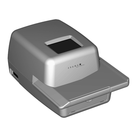
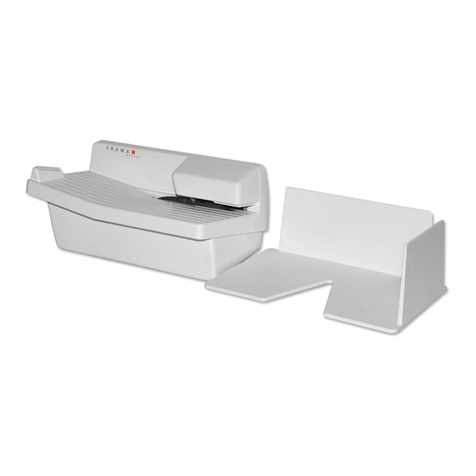
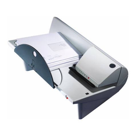
Illustration 1 Letter Opener Access B400.................................................................................................................... 7
Illustration 2 Disassembling / Protective Cover............................................................................................................ 9
Illustration 3 Disassembling / Separator Unit .............................................................................................................. 9
Illustration 4 Disassembling / Housing........................................................................................................................ 9
Illustration 5 Disassembling / Main Board................................................................................................................. 10
Illustration 6 Disassembling / Mechanic.................................................................................................................... 10
Illustration 7 Disassembling / Mechanic.................................................................................................................... 10
Illustration 8 Disassembling / Cutter......................................................................................................................... 11
Illustration 9 Disassembling / Mechanic.................................................................................................................... 11
Illustration 10 Disassembling / Letter Edge Stop ....................................................................................................... 12
Illustration 11 Letter edge stop ................................................................................................................................ 12
Illustration 12 Letter edge stop ................................................................................................................................ 12
Illustration 13 Assembling / Motor Position.............................................................................................................. 14
Illustration 14 Assembling / Drive Belt...................................................................................................................... 14
Illustration 15 Assembling / Mechanic...................................................................................................................... 15
Illustration 16 Assembling / Ball Bearing................................................................................................................... 16
Illustration 17 Assembling / Fan ............................................................................................................................... 16
Illustration 18 Assembling / red power bulb............................................................................................................. 16
Illustration 19 Assembling / Connection Plan ........................................................................................................... 17
Illustration 20 Assembling / Upper Housing.............................................................................................................. 17
Illustration 21 Adjustment / Cutter........................................................................................................................... 19
Illustration 22 Adjustment / Optimal Cut of Letter.................................................................................................... 19
